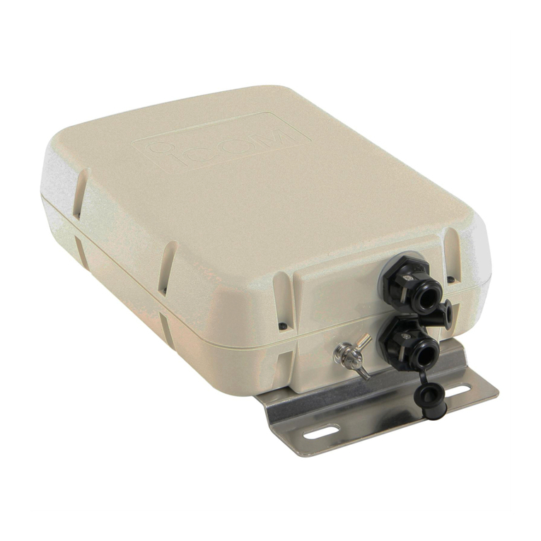
Icom AH-730 User manual

INSTRUCTIONS
AUTOMATIC ANTENNA TUNER Thank you for choosing this Icom product.
READ ALL INSTRUCTIONS carefully and completely
before using this product.
1-1-32 Kamiminami, Hirano-ku, Osaka 547-0003, Japan
Jan. 2022
A7669W-1EX Printed in Japan
© 2022 Icom Inc. –1 –
–4 –
AH-730
■Important
SAVE THESE INSTRUCTIONS— These instructions
contain important operating instructions for the AH-730.
■Precaution
RDANGER! NEVER operate the antenna tuner without a solid
ground. Always connect the ground wire to the ground terminal. DO
NOT use the mounting plate as a ground terminal.
RDANGER! NEVER transmit or tune without an antenna
connected. Failure to use an antenna will damage the antenna tuner.
RDANGER! HIGH VOLTAGE! NEVER touch the antenna while
transmitting or tuning. Place the antenna in a position where you
are sure it will not be touched.
KEEP the antenna tuner away from heavy rain and never immerse
it in water. The antenna tuner meets IPX4 requirements for splash
resistance. However, once the antenna tuner has been dropped, splash
resistance cannot be guaranteed due to the fact that the antenna tuner
may be cracked or the waterproof seal damaged, and so on.
Ground terminal
Mounting plate
■Features
• Wide tuning range
The AH-730 provides reliable matching from 1.8 MHz to
54 MHz when using at least a 7 m (23 ft) antenna or 3.5
MHz to 54 MHz when using the AH-2b .
• Automatic digital control tuning
The built-in 32 bit microprocessor chooses the lowest
SWR using more than 1,040,000 different LC (coil/
capacitor) combinations.
• 45 frequency memories for fast tuning
The LC combinations of 45 previously-used frequencies
are automatically memorized. Once a frequency is
memorized, the AH-730 tunes on that frequency in less
than 1 second. Note that the AH-730 does not memorize
a frequency which is normally tuned within 2.5 seconds.
Memories are retained only when the power is on.
• 0.3 W radiated power
Radiated power during tuning is less than 0.3 W,
minimizing interference to other stations.
• IPX4 weatherproof design
The AH-730’s tightly sealed plastic case allows
convenient mounting virtually anywhere. The AH-730 can
be mounted outdoors under your antenna.
NOTE: The AH-730 can be used with most of Icom HF
transceiver, which covers HF through 50 MHz bands.
However, the IC-706 and IC-736 can only be tuned in the
1.8 ~ 30 MHz range.
■FCC information
This equipment has been tested and found to comply with the limits
for a Class B digital device, pursuant to part 15 of the FCC Rules.
These limits are designed to provide reasonable protection against
harmful interference in a residential installation. This equipment
generates, uses, and can radiate radio frequency energy and, if
not installed and used in accordance with the instructions, may
cause harmful interference to radio communications. However,
there is no guarantee that interference will not occur in a particular
installation. If this equipment does cause harmful interference to
radio or television reception, which can be determined by turning
the equipment off and on, the user is encouraged to try to correct
the interference by one or more of the following measures:
• Reorient or relocate the receiving antenna.
• Increase the separation between the equipment and receiver.
• Connect the equipment into an outlet on a circuit different
from that to which the receiver is connected.
• Consult the dealer or an experienced radio/TV technician for help.
CAUTION: Changes or modifications to this device, not expressly
approved by Icom Inc., could void your authority to operate this
device under FCC regulations.
This device complies with part 15 of the FCC Rules. Operation is
subject to the following two conditions: (1) This device may not cause
harmful interference, and (2) this device must accept any interference
received, Including interference that may cause undesired operation.
Icom, Icom Inc. and the Icom logo are registered trademarks of Icom Incorporated (Japan) in Japan, the United States, the
United Kingdom, Germany, France, Spain, Russia, Australia, New Zealand, and/or other countries.
■Specications
• Frequency range: 1.8 ~ 54 MHz (with an antenna
longer than 7 m, 23 ft)
3.5 ~ 54 MHz (with the AH-2b)
• Maximum input power: 150 W
•
• Tuning power required: 5 ~ 15 watts
• Rated voltage: 13.8 V DC ±15%
(current less than 0.7 A)
• Usable temperature range:
–10°C ~ +60°C
(+14°F ~ +140°F)
• VSWR: 2.0 : 1 or less (except antennas
a one half wave or multiple of a
one half wave in length)
• Weight (approximate): 2.5 kg (5.5 lb)
• Dimensions: 230 (W) × 80 (H) × 340 (D) mm,
(projections not included)
9.1 (W) × 3.1 (H) × 13.4 (D) inches
LAll stated specifications are typical and subject to change without
notice or obligation.
■Options
• OPC-1465
Cable length (approximate): 10 m, 32.8 ft
The same as supplied.
• AH-2b
A 2.5 m long antenna element for mobile operation with AH-730.
Frequency coverage: 3.5 ~ 54 MHz with the AH-730.
■Supplied accessories
U-bolts Hex head bolts (M6 × 50)
U-bolt plates
Self-tapping screws
(A0 6 × 30)
Flat washers (M6 large)
Weatherproof
cap
Rubber
vulcanizing tape
Control cable
(Approximately 10 m, 32.8 ft
(without ground wires))
Flat washers (M6 small)
Spring washers (M6)
Nuts (M6)
■Installation
DMounting examples
RDANGER! HIGH VOLTAGE! NEVER touch the antenna while transmitting or tuning. Place the antenna in a position where
you are sure it will not be touched.
AH-2b + long wire
AH-2b
(optional)
Long wire
Long wire
Icom is not responsible for the destruction, damage to, or
performance of any Icom or non-Icom equipment, if the
malfunction is because of:
• Force majeure, including, but not limited to, fires,
earthquakes, storms, floods, lightning, other natural disasters,
disturbances, riots, war, or radioactive contamination.
• The use of Icom antenna tuners with any equipment
that is not manufactured or approved by Icom.
■Operation
Tuning is required for each frequency. Be sure to retune
the antenna before transmitting when you change the
frequency— even slightly.
Example: IC-7300
1. Turn ON the transceiver.
• Each time you push
TUNER
, “TUNE” is displayed or goes
out, and the AH-730 is turned ON or OFF (bypassed).
2. Hold down
TUNER
for 1 second to start manual tuning.
• The antenna tuner reduces the SWR to less than 2:1 after 2 ~
3 seconds of tuning.
LWhile tuning, “TUNE” blinks red.
LIf the antenna tuner cannot reduce the SWR to less than 2:1
after 15 seconds of tuning, “TUNE” goes out.
Hold down
TUNER
for 1 second.
3. After tuning, “TUNE” is displayed.
L
When the long wire antenna cannot be tuned, “TUNE” goes out. In
that case, the AH-730 is bypassed and the wire is directly connected.
NOTE: When the wire antenna cannot be tuned, confirm wire
length and connection. Note that the AH-730 cannot tune a
■Explicit denitions
WORD DEFINITION
RDANGER! Personal death, serious injury or an
explosion may occur.
RWARNING! Personal injury, fire hazard or electric shock
may occur.
CAUTION Equipment damage may occur.
NOTE If disregarded, inconvenience only. No risk
of personal injury, fire or electric shock.
Below statement is for UKCA purpose only
United Kingdom Authorised Importer: Icom (UK) Ltd.
Address: Blacksole House, Altira Park, Herne Bay, Kent,
CT6 6GZ, U.K.

INSTRUCTIONS
AUTOMATIC ANTENNA TUNER Thank you for choosing this Icom product.
READ ALL INSTRUCTIONS carefully and completely
before using this product.
1-1-32 Kamiminami, Hirano-ku, Osaka 547-0003, Japan
Jan. 2022
A7669W-1EX Printed in Japan
© 2022 Icom Inc. –1 –
–4 –
AH-730
■Important
SAVE THESE INSTRUCTIONS— These instructions
contain important operating instructions for the AH-730.
■Precaution
RDANGER! NEVER operate the antenna tuner without a solid
ground. Always connect the ground wire to the ground terminal. DO
NOT use the mounting plate as a ground terminal.
RDANGER! NEVER transmit or tune without an antenna
connected. Failure to use an antenna will damage the antenna tuner.
RDANGER! HIGH VOLTAGE! NEVER touch the antenna while
transmitting or tuning. Place the antenna in a position where you
are sure it will not be touched.
KEEP the antenna tuner away from heavy rain and never immerse
it in water. The antenna tuner meets IPX4 requirements for splash
resistance. However, once the antenna tuner has been dropped, splash
resistance cannot be guaranteed due to the fact that the antenna tuner
may be cracked or the waterproof seal damaged, and so on.
Ground terminal
Mounting plate
■Features
• Wide tuning range
The AH-730 provides reliable matching from 1.8 MHz to
54 MHz when using at least a 7 m (23 ft) antenna or 3.5
MHz to 54 MHz when using the AH-2b .
• Automatic digital control tuning
The built-in 32 bit microprocessor chooses the lowest
SWR using more than 1,040,000 different LC (coil/
capacitor) combinations.
• 45 frequency memories for fast tuning
The LC combinations of 45 previously-used frequencies
are automatically memorized. Once a frequency is
memorized, the AH-730 tunes on that frequency in less
than 1 second. Note that the AH-730 does not memorize
a frequency which is normally tuned within 2.5 seconds.
Memories are retained only when the power is on.
• 0.3 W radiated power
Radiated power during tuning is less than 0.3 W,
minimizing interference to other stations.
• IPX4 weatherproof design
The AH-730’s tightly sealed plastic case allows
convenient mounting virtually anywhere. The AH-730 can
be mounted outdoors under your antenna.
NOTE: The AH-730 can be used with most of Icom HF
transceiver, which covers HF through 50 MHz bands.
However, the IC-706 and IC-736 can only be tuned in the
1.8 ~ 30 MHz range.
■FCC information
This equipment has been tested and found to comply with the limits
for a Class B digital device, pursuant to part 15 of the FCC Rules.
These limits are designed to provide reasonable protection against
harmful interference in a residential installation. This equipment
generates, uses, and can radiate radio frequency energy and, if
not installed and used in accordance with the instructions, may
cause harmful interference to radio communications. However,
there is no guarantee that interference will not occur in a particular
installation. If this equipment does cause harmful interference to
radio or television reception, which can be determined by turning
the equipment off and on, the user is encouraged to try to correct
the interference by one or more of the following measures:
• Reorient or relocate the receiving antenna.
• Increase the separation between the equipment and receiver.
• Connect the equipment into an outlet on a circuit different
from that to which the receiver is connected.
• Consult the dealer or an experienced radio/TV technician for help.
CAUTION: Changes or modifications to this device, not expressly
approved by Icom Inc., could void your authority to operate this
device under FCC regulations.
This device complies with part 15 of the FCC Rules. Operation is
subject to the following two conditions: (1) This device may not cause
harmful interference, and (2) this device must accept any interference
received, Including interference that may cause undesired operation.
Icom, Icom Inc. and the Icom logo are registered trademarks of Icom Incorporated (Japan) in Japan, the United States, the
United Kingdom, Germany, France, Spain, Russia, Australia, New Zealand, and/or other countries.
■Specications
• Frequency range: 1.8 ~ 54 MHz (with an antenna
longer than 7 m, 23 ft)
3.5 ~ 54 MHz (with the AH-2b)
• Maximum input power: 150 W
•
• Tuning power required: 5 ~ 15 watts
• Rated voltage: 13.8 V DC ±15%
(current less than 0.7 A)
• Usable temperature range:
–10°C ~ +60°C
(+14°F ~ +140°F)
• VSWR: 2.0 : 1 or less (except antennas
a one half wave or multiple of a
one half wave in length)
• Weight (approximate): 2.5 kg (5.5 lb)
• Dimensions: 230 (W) × 80 (H) × 340 (D) mm,
(projections not included)
9.1 (W) × 3.1 (H) × 13.4 (D) inches
LAll stated specifications are typical and subject to change without
notice or obligation.
■Options
• OPC-1465
Cable length (approximate): 10 m, 32.8 ft
The same as supplied.
• AH-2b
A 2.5 m long antenna element for mobile operation with AH-730.
Frequency coverage: 3.5 ~ 54 MHz with the AH-730.
■Supplied accessories
U-bolts Hex head bolts (M6 × 50)
U-bolt plates
Self-tapping screws
(A0 6 × 30)
Flat washers (M6 large)
Weatherproof
cap
Rubber
vulcanizing tape
Control cable
(Approximately 10 m, 32.8 ft
(without ground wires))
Flat washers (M6 small)
Spring washers (M6)
Nuts (M6)
■Installation
DMounting examples
RDANGER! HIGH VOLTAGE! NEVER touch the antenna while transmitting or tuning. Place the antenna in a position where
you are sure it will not be touched.
AH-2b + long wire
AH-2b
(optional)
Long wire
Long wire
Icom is not responsible for the destruction, damage to, or
performance of any Icom or non-Icom equipment, if the
malfunction is because of:
• Force majeure, including, but not limited to, fires,
earthquakes, storms, floods, lightning, other natural disasters,
disturbances, riots, war, or radioactive contamination.
• The use of Icom antenna tuners with any equipment
that is not manufactured or approved by Icom.
■Operation
Tuning is required for each frequency. Be sure to retune
the antenna before transmitting when you change the
frequency— even slightly.
Example: IC-7300
1. Turn ON the transceiver.
• Each time you push
TUNER
, “TUNE” is displayed or goes
out, and the AH-730 is turned ON or OFF (bypassed).
2. Hold down
TUNER
for 1 second to start manual tuning.
• The antenna tuner reduces the SWR to less than 2:1 after 2 ~
3 seconds of tuning.
LWhile tuning, “TUNE” blinks red.
LIf the antenna tuner cannot reduce the SWR to less than 2:1
after 15 seconds of tuning, “TUNE” goes out.
Hold down
TUNER
for 1 second.
3. After tuning, “TUNE” is displayed.
L
When the long wire antenna cannot be tuned, “TUNE” goes out. In
that case, the AH-730 is bypassed and the wire is directly connected.
NOTE: When the wire antenna cannot be tuned, confirm wire
length and connection. Note that the AH-730 cannot tune a
■Explicit denitions
WORD DEFINITION
RDANGER! Personal death, serious injury or an
explosion may occur.
RWARNING! Personal injury, fire hazard or electric shock
may occur.
CAUTION Equipment damage may occur.
NOTE If disregarded, inconvenience only. No risk
of personal injury, fire or electric shock.
Below statement is for UKCA purpose only
United Kingdom Authorised Importer: Icom (UK) Ltd.
Address: Blacksole House, Altira Park, Herne Bay, Kent,
CT6 6GZ, U.K.

–3 –– 2 –
DCable connections
NOTE: Connect a user supplied coaxial cable to the appropriate antenna connector if the transceiver has more than one. See
your transceiver’s instruction manual for details.
Example: IC-7300
DGround connections
The ground wire of the antenna tuner is used as an antenna
element. The transceiver and antenna tuner must have
an adequate ground connection. Otherwise, the overall
efficiency of the transceiver and antenna tuner installation
will be reduced. Interference, RF feedback, and electrical
shocks from other equipment could also occur.
For best results, use the heaviest gauge wire or strap
available, and make the connection as short as possible, as
shown below.
LA long wire connected to the GND terminal as a counterpoise is
also acceptable.
To the AH-730 GND terminal
Copper pipe Metal object Copper screen
DMounting the AH-730
CAUTION: Mount the AH-730 in a horizontal position or a vertical position with the antenna terminal up.
• Mounting on an antenna pole
Using the supplied U-bolts
32 ~ 60 mm
U-bolt plate
Spring washer
U-bolt
Flat washer (L)
Flat washer (S)
Nut
RWARNING! Mount the AH-730 securely with the
supplied nuts and bolts. Otherwise, vibrations and
shocks could loosen the antenna tuner, making it fall,
causing personal injury.
CAUTION: DO NOT mount the
antenna tuner upside down.
• Mounting on a flat location
Using nuts and bolts Using self-tapping screws
Spring washer
Flat washer (L)
Flat washer (L)
Flat washer (S)
Hex head bolt
Nut
■Installation
DWaterproong the antenna connection
CAUTION: If you skip the following steps, moisture will
get into the connector, and this could damage the antenna
tuner.
CAUTION:
• NEVER modify, bend, twist, pull or heat the control cable and the coaxial cable.
• NEVER hang something heavy on the control cable and the coaxial cable.
• NEVER mount the AH-730 without securing the control cable and the coaxial cable so that they cannot be pulled or
stretched.
1. Cut off just the top of the weatherproof cap, and pass
the antenna wire through the cap.
Antenna wire
Weatherproof cap
2. Insert the antenna wire into the opening of the crimp-on
wire terminal.
LCrimp or solder the antenna wire.
Crimp Solder
3. Put the crimp-on wire terminal, star washer, and wing
nut on the base nut, in that order, and then tighten the
wing nut.
LMake sure the base nut is tightened firmly before you
tighten the wing nut, as shown below.
LCarefully bend the wire terminal up after you tighten the
wing nut. (1)
Antenna tuner
Base nut
Crimp-on wire terminal
Star washer
Wing nut
4. Place the weatherproof cap over as much of the
insulator as possible. (2)
LHow far down it will go depends on the height of the wing
nut.
5. Start wrapping the rubber vulcanizing tape at the bottom
of the insulator, then the weatherproof cap, and finally
the antenna wire to prevent water seeping. (3)
LWrap user supplied electrical tape over the rubber
vulcanizing tape to secure waterproofing.
8-Insulator
Bend this part up
after you tighten
the wing nut. Rubber
vulcanizing tape
Coaxial cable
(User supplied)
GND
GND
Control cable
(Supplied cable:10 m, 32.8 ft
Optional cable: 10 m, 32.8 ft)
AH-730
IC-7300
Ground wire
LIf RF feedback occurs, connect
the control cable ground to both
the AH-730 GND and the IC-7300
GND terminals.
Ground wire
■Disposal
The crossed-out wheeled-bin symbol on your
product, literature, or packaging reminds you
that in the European Union, all electrical and
electronic products, batteries, and accumulators
(rechargeable batteries) must be taken to
designated collection locations at the end of their working
life. Do not dispose of these products as unsorted municipal
waste. Dispose of them according to the laws in your area.
■About CE and DOC
Hereby, Icom Inc. declares that the versions
of AH-730 which have the “CE” symbol on the
product, comply with the essential requirements
of the Radio Equipment Directive, 2014/53/EU,
and the restriction of the use of certain hazardous substances
in electrical and electronic equipment Directive, 2011/65/EU.
The full text of the EU declaration of conformity is available at
the following internet address:
https://www.icomjapan.com/support/

INSTRUCTIONS
AUTOMATIC ANTENNA TUNER Thank you for choosing this Icom product.
READ ALL INSTRUCTIONS carefully and completely
before using this product.
1-1-32 Kamiminami, Hirano-ku, Osaka 547-0003, Japan
Jan. 2022
A7669W-1EX Printed in Japan
© 2022 Icom Inc. –1 –
–4 –
AH-730
■Important
SAVE THESE INSTRUCTIONS— These instructions
contain important operating instructions for the AH-730.
■Precaution
RDANGER! NEVER operate the antenna tuner without a solid
ground. Always connect the ground wire to the ground terminal. DO
NOT use the mounting plate as a ground terminal.
RDANGER! NEVER transmit or tune without an antenna
connected. Failure to use an antenna will damage the antenna tuner.
RDANGER! HIGH VOLTAGE! NEVER touch the antenna while
transmitting or tuning. Place the antenna in a position where you
are sure it will not be touched.
KEEP the antenna tuner away from heavy rain and never immerse
it in water. The antenna tuner meets IPX4 requirements for splash
resistance. However, once the antenna tuner has been dropped, splash
resistance cannot be guaranteed due to the fact that the antenna tuner
may be cracked or the waterproof seal damaged, and so on.
Ground terminal
Mounting plate
■Features
• Wide tuning range
The AH-730 provides reliable matching from 1.8 MHz to
54 MHz when using at least a 7 m (23 ft) antenna or 3.5
MHz to 54 MHz when using the AH-2b .
• Automatic digital control tuning
The built-in 32 bit microprocessor chooses the lowest
SWR using more than 1,040,000 different LC (coil/
capacitor) combinations.
• 45 frequency memories for fast tuning
The LC combinations of 45 previously-used frequencies
are automatically memorized. Once a frequency is
memorized, the AH-730 tunes on that frequency in less
than 1 second. Note that the AH-730 does not memorize
a frequency which is normally tuned within 2.5 seconds.
Memories are retained only when the power is on.
• 0.3 W radiated power
Radiated power during tuning is less than 0.3 W,
minimizing interference to other stations.
• IPX4 weatherproof design
The AH-730’s tightly sealed plastic case allows
convenient mounting virtually anywhere. The AH-730 can
be mounted outdoors under your antenna.
NOTE: The AH-730 can be used with most of Icom HF
transceiver, which covers HF through 50 MHz bands.
However, the IC-706 and IC-736 can only be tuned in the
1.8 ~ 30 MHz range.
■FCC information
This equipment has been tested and found to comply with the limits
for a Class B digital device, pursuant to part 15 of the FCC Rules.
These limits are designed to provide reasonable protection against
harmful interference in a residential installation. This equipment
generates, uses, and can radiate radio frequency energy and, if
not installed and used in accordance with the instructions, may
cause harmful interference to radio communications. However,
there is no guarantee that interference will not occur in a particular
installation. If this equipment does cause harmful interference to
radio or television reception, which can be determined by turning
the equipment off and on, the user is encouraged to try to correct
the interference by one or more of the following measures:
• Reorient or relocate the receiving antenna.
• Increase the separation between the equipment and receiver.
• Connect the equipment into an outlet on a circuit different
from that to which the receiver is connected.
• Consult the dealer or an experienced radio/TV technician for help.
CAUTION: Changes or modifications to this device, not expressly
approved by Icom Inc., could void your authority to operate this
device under FCC regulations.
This device complies with part 15 of the FCC Rules. Operation is
subject to the following two conditions: (1) This device may not cause
harmful interference, and (2) this device must accept any interference
received, Including interference that may cause undesired operation.
Icom, Icom Inc. and the Icom logo are registered trademarks of Icom Incorporated (Japan) in Japan, the United States, the
United Kingdom, Germany, France, Spain, Russia, Australia, New Zealand, and/or other countries.
■Specications
• Frequency range: 1.8 ~ 54 MHz (with an antenna
longer than 7 m, 23 ft)
3.5 ~ 54 MHz (with the AH-2b)
• Maximum input power: 150 W
•
• Tuning power required: 5 ~ 15 watts
• Rated voltage: 13.8 V DC ±15%
(current less than 0.7 A)
• Usable temperature range:
–10°C ~ +60°C
(+14°F ~ +140°F)
• VSWR: 2.0 : 1 or less (except antennas
a one half wave or multiple of a
one half wave in length)
• Weight (approximate): 2.5 kg (5.5 lb)
• Dimensions: 230 (W) × 80 (H) × 340 (D) mm,
(projections not included)
9.1 (W) × 3.1 (H) × 13.4 (D) inches
LAll stated specifications are typical and subject to change without
notice or obligation.
■Options
• OPC-1465
Cable length (approximate): 10 m, 32.8 ft
The same as supplied.
• AH-2b
A 2.5 m long antenna element for mobile operation with AH-730.
Frequency coverage: 3.5 ~ 54 MHz with the AH-730.
■Supplied accessories
U-bolts Hex head bolts (M6 × 50)
U-bolt plates
Self-tapping screws
(A0 6 × 30)
Flat washers (M6 large)
Weatherproof
cap
Rubber
vulcanizing tape
Control cable
(Approximately 10 m, 32.8 ft
(without ground wires))
Flat washers (M6 small)
Spring washers (M6)
Nuts (M6)
■Installation
DMounting examples
RDANGER! HIGH VOLTAGE! NEVER touch the antenna while transmitting or tuning. Place the antenna in a position where
you are sure it will not be touched.
AH-2b + long wire
AH-2b
(optional)
Long wire
Long wire
Icom is not responsible for the destruction, damage to, or
performance of any Icom or non-Icom equipment, if the
malfunction is because of:
• Force majeure, including, but not limited to, fires,
earthquakes, storms, floods, lightning, other natural disasters,
disturbances, riots, war, or radioactive contamination.
• The use of Icom antenna tuners with any equipment
that is not manufactured or approved by Icom.
■Operation
Tuning is required for each frequency. Be sure to retune
the antenna before transmitting when you change the
frequency— even slightly.
Example: IC-7300
1. Turn ON the transceiver.
• Each time you push
TUNER
, “TUNE” is displayed or goes
out, and the AH-730 is turned ON or OFF (bypassed).
2. Hold down
TUNER
for 1 second to start manual tuning.
• The antenna tuner reduces the SWR to less than 2:1 after 2 ~
3 seconds of tuning.
LWhile tuning, “TUNE” blinks red.
LIf the antenna tuner cannot reduce the SWR to less than 2:1
after 15 seconds of tuning, “TUNE” goes out.
Hold down
TUNER
for 1 second.
3. After tuning, “TUNE” is displayed.
L
When the long wire antenna cannot be tuned, “TUNE” goes out. In
that case, the AH-730 is bypassed and the wire is directly connected.
NOTE: When the wire antenna cannot be tuned, confirm wire
length and connection. Note that the AH-730 cannot tune a
■Explicit denitions
WORD DEFINITION
RDANGER! Personal death, serious injury or an
explosion may occur.
RWARNING! Personal injury, fire hazard or electric shock
may occur.
CAUTION Equipment damage may occur.
NOTE If disregarded, inconvenience only. No risk
of personal injury, fire or electric shock.
Below statement is for UKCA purpose only
United Kingdom Authorised Importer: Icom (UK) Ltd.
Address: Blacksole House, Altira Park, Herne Bay, Kent,
CT6 6GZ, U.K.
Table of contents
Other Icom Tuner manuals