TABLE
OF
CONTENTS
IMPORTANT
..
PRECAUTIONS
accssssssscssssosssssssassssrsesssnessssovesseaes
EXPLICIT
DEFINITIONS.
...........essssssssessssnseneseesesseeseesel
FOREWORD
..
MISCELLANEOUS
ITEMS
........sccsssessesssssserseesseesneeseed
TABLE
OF
CONTENTS
|...
n0iessnsecsssncencssonssnsseensmsonsall
FEATURES
sissisiscicssanrernncrnermninnnes
pinacapenceaseieiinnse
ii
1
ANTENNA
SYSTEM.
WAntenna
for
ship.....
Antenna
for
land
operation
.
Coaxial
cable
............00
Ground
and
counterpoise
2
INSTALLATIONS
Minstallation
outline
.
Cable
installation
MIPL-259
connector
.
Control
cable
..
Cable
connectio:
Mounting
12
PRAwBOOR
NN
3
INTERNAL
SETTINGS
.
Before
internal
settings
Mode
switch
..
Preset
tuning
Emergency
tuning
(AT-130E)
4
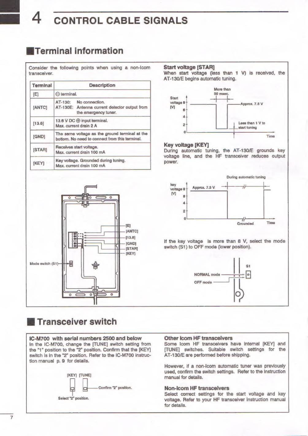
CONTROL
CABLE
SIGNALS
Terminal
information
Transceiver
switch
5
INSIDE
VIEW
AND
SPECIFICATIONS
................
Miinside
view..
Specifications
oO
VYN
onuug
FEATURES
Matches
all
bands
The
AT-130/E
matches
any
frequency
on
every
HF
marine
band.
For
example,
the
tuner
matches
a
7
m;
23.0
feet
long-wire
antenna
across
1.6—30
MHz.
Full
automatic
tuning
Just
push
the
[TUNE]
switch
on
a
transceiver,
the
AT-130/E
adjusts
immediately
to
the
minimum
SWR
in
any
frequency
on
any
HF
marine
band.
HF
operation
on
any
size
ship
The
AT-130/E
allows
you
HF
operation
where
antenna
element
length
is
restricted
due
to
space.
Weather
resistant
The
AT-130/E
is
housed
in
a
durable,
completely
weather-
resistant
acrylic
case
with
a
rubber
gasket.
The
antenna
tuner
can
be
conveniently
installed
both
on
the
deck
or
in
the
cabin
near
the
antenna
element.
Simple
installation
Installation
is
simple.
Just
connect
the
control
and
antenna
cables
and
short-time
internal
settings.
After
installation,
you
never
need
to
open
the
cover
for
maintenance.
Preset
tuning
function
This
function
provides
super
fast
tuning
on
your
most-used
frequency.
45
memories
for
shorter
tuning
time
To
decrease
the
tune-up
time,
the
AT-130/E
automatically
stores
the
matching
conditions
for
up
to
45
frequencies.
Retuning
for
a
memorized
frequency
takes
only
approx.
1
sec,
Super
capacitor
for
memory
backup
Even
if
the
AT-130/E
is
not
used
for
approx.
1
week,
the
built-in
super
capacitor
backs
up
the
45
memory
contents.
Low
power
tune
up
The
AT-130/E
emits
low
output
power
during
tuning.
This
feature
reduces
the
possibility
of
causing
interference
to
other
stations.
Emergency
tuner
circuit
(AT-130E)
To
meet
with
European
regulations,
the
Europe
version
AT-130E
includes
an
emergency
tuner
circuit
for
2182
kHz
operation.
If
any
signal
from
the
control
cable
indicates
an
abnormal
condition,
this
circuit
is
automatically
selected.