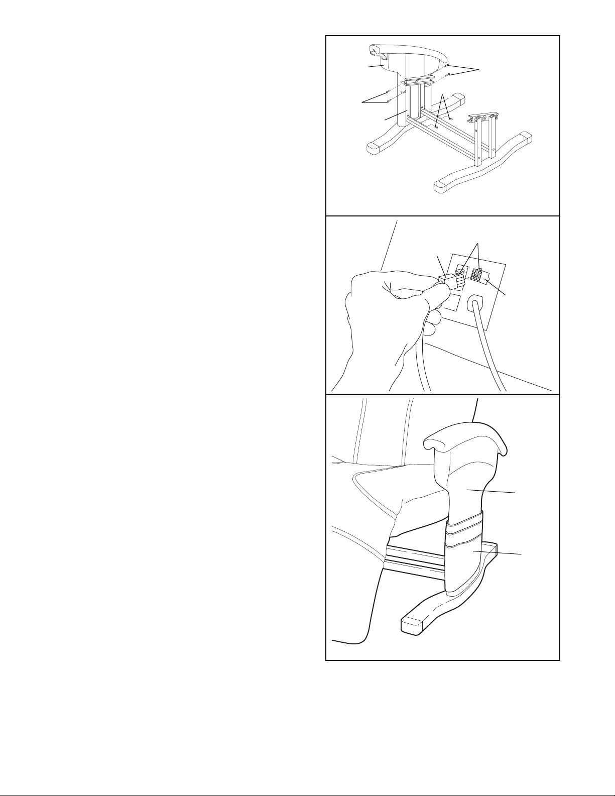
HOW TO PLUG IN THE POWER CORD
Your massage chair, like any other type of sophisticat-
ed electronic equipment, can be seriously damaged
by sudden voltage changes in your homeÕs power.
Voltage surges, spikes, and noise interference can
result from weather conditions or from other appli-
ances being turned on or off. To decrease the possi-
bility of your massage chair being damaged,
always use a surge suppressor with your mas-
sage chair (see drawing 1 below).
Surge suppressors are sold at most hardware stores
and department stores. Use only a single-outlet surge
suppressor that is UL 1449 listed as a transient volt-
age surge suppressor (TVSS). The surge suppressor
must have a UL suppressed voltage rating of 400
volts or less and a minimum surge dissipation of 450
joules. The surge suppressor must be electrically
rated for 120 volts AC and 15 amps.
This product must be grounded. If it should mal-
function or break down, grounding provides a path of
least resistance for electric current to reduce the risk
of electric shock. This product is equipped with a cord
having an equipment-grounding conductor and a
grounding plug. Plug the power cord into a surge
suppressor, and plug the surge suppressor into
an appropriate outlet that is properly installed and
grounded in accordance with all local codes and
ordinances.
This product is for use on a nominal 120-volt circuit,
and has a grounding plug that looks like the plug illus-
trated in drawing 1. A temporary adapter that looks
like the adapter illustrated in drawing 2 may be used
to connect the surge suppressor to a 2-pole
receptacle as shown in drawing 2 if a properly
grounded outlet is not available.
The temporary adapter should be used only until a
properly grounded outlet (drawing 1) can be installed
by a qualified electrician.
The green-colored rigid ear, lug or the like extending
from the adapter must be connected to a permanent
ground such as a properly grounded outlet box cover.
Whenever the adapter is used it must be held in place
by a metal screw. Some 2-pole receptacle outlet
box covers are not grounded. Contact a qualified
electrician to determine if the outlet box cover is
grounded before using an adapter.
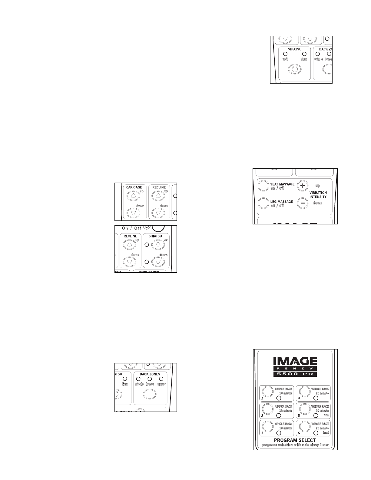
HOW TO TURN ON THE POWER
Make sure the power switch
on the back of the chair is
in the ÒonÓ position.
Next, press the power but-
ton on the hand control; an
indicator will light. Note: If
there is a thin sheet of plas-
tic on the face of the hand
control, remove it.
HOW TO TURN OFF THE POWER
To turn off the power, press the power button on the
hand control. The power indicator will darken. Return
the power switch on the back of the chair to the ÒoffÓ
position.
DANGER: Improper connection
of the equipment-grounding conductor can
result in an increased risk of electric shock.
Check with a qualified electrician or service-
man if you are in doubt as to whether the
product is properly grounded. Do not modify
the plug provided with the productÑif it will
not fit the outlet, have a proper outlet
installed by a qualified electrician.
1
2
Grounded Outlet Box
Grounded Outlet Box
Grounding Plug
Surge Suppressor
Surge Suppressor
Grounding Pin
Adapter
Lug
Metal Screw
Grounded Outlet
Grounding Pin
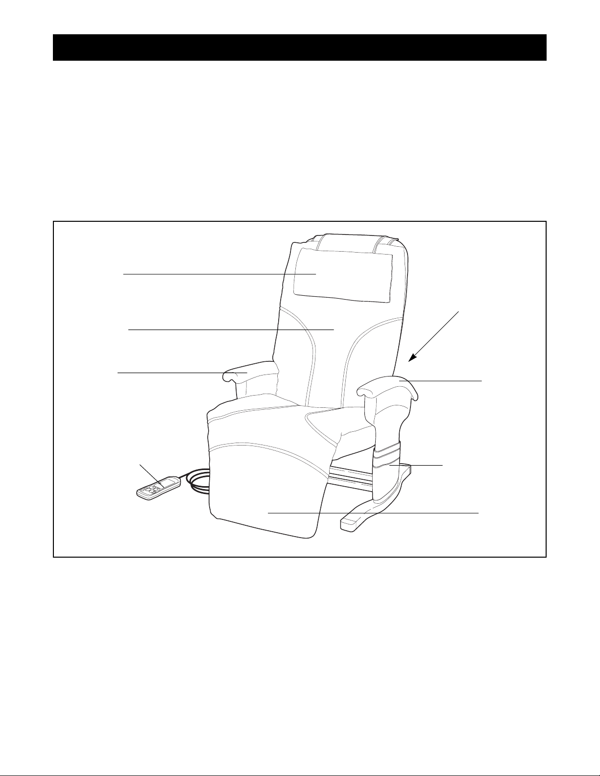
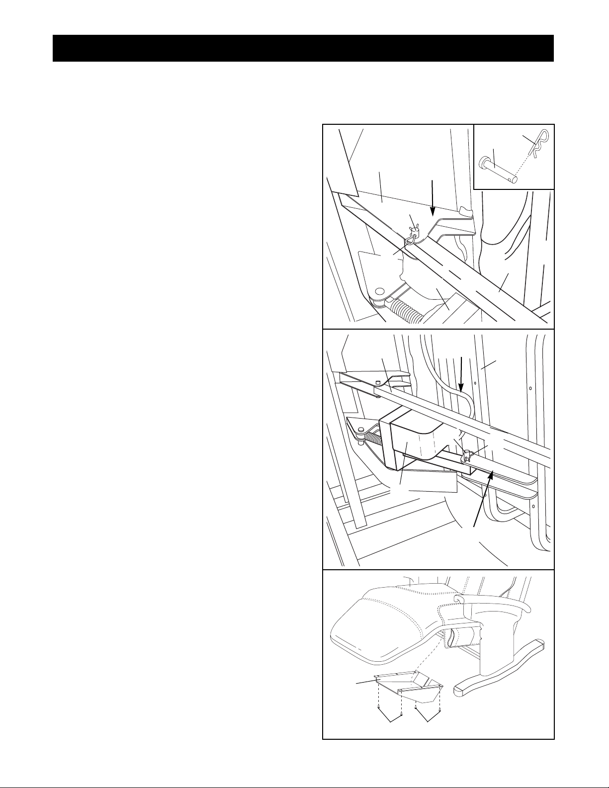
How to Operate the Massage Chair
Power Button
8