ICP DAS USA ALM-Horn Series User manual

ALM-Horn Series User’s Manual
ALM-Horn Series User’s Manual (Rev1.0, NOV/2020) ------------- 1
www.icpdas.com
Warranty
All products manufactured by ICP DAS are under warranty regarding
defective materials for a period of one year from the date of delivery to the
original purchaser.
Warning
ICP DAS assumes no liability for damages resulting from the use of this
product. ICP DAS reserves the right to change this manual at any time without
notice. The information furnished by ICP DAS is believed to be accurate and
reliable. However, no responsibility is assumed by ICP DAS for its use, or for any
infringements of patents or other rights of third parties resulting from its use.
Copyright
Copyright 2020 by ICP DAS. All rights are reserved.
Trademark
The names used for identification only may be registered trademarks of their
respective companies.

ALM-Horn Series User’s Manual
ALM-Horn Series User’s Manual (Rev1.0, NOV/2020) ------------- 2
Document Revision
Version Date Description of chan
g
es
Rev1.0 2020-11-04 First
r
elease for ALM-Horn Series

ALM-Horn Series User’s Manual
ALM-Horn Series User’s Manual (Rev1.0, NOV/2020) ------------- 3
Table of Contents
1.Introduction ...................................................................................................... 4
1.1Features .............................................................................................. 5
1.1.1Features Description ........................................................................... 5
1.2Specifications ...................................................................................... 6
2.Hardware .......................................................................................................... 8
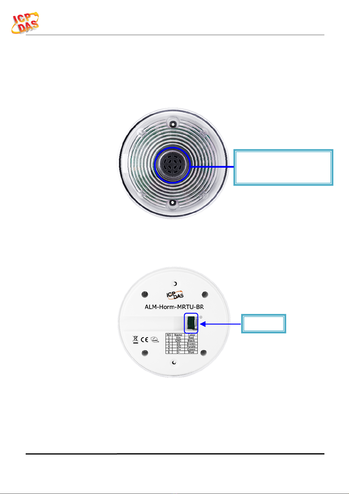
2.1Outward Appearance .......................................................................... 8
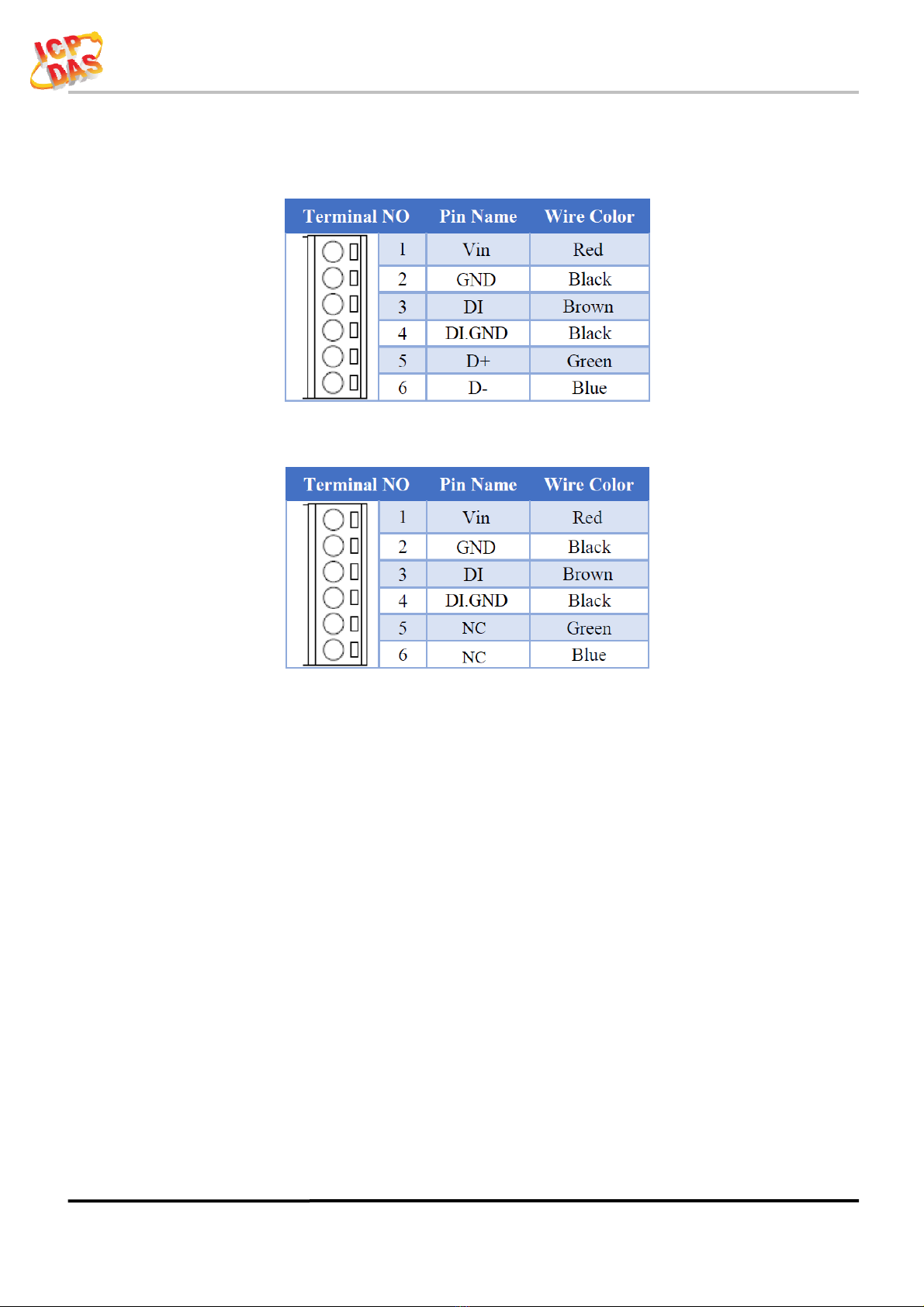
2.1.2Connector Pin Define ....................................................................... 9
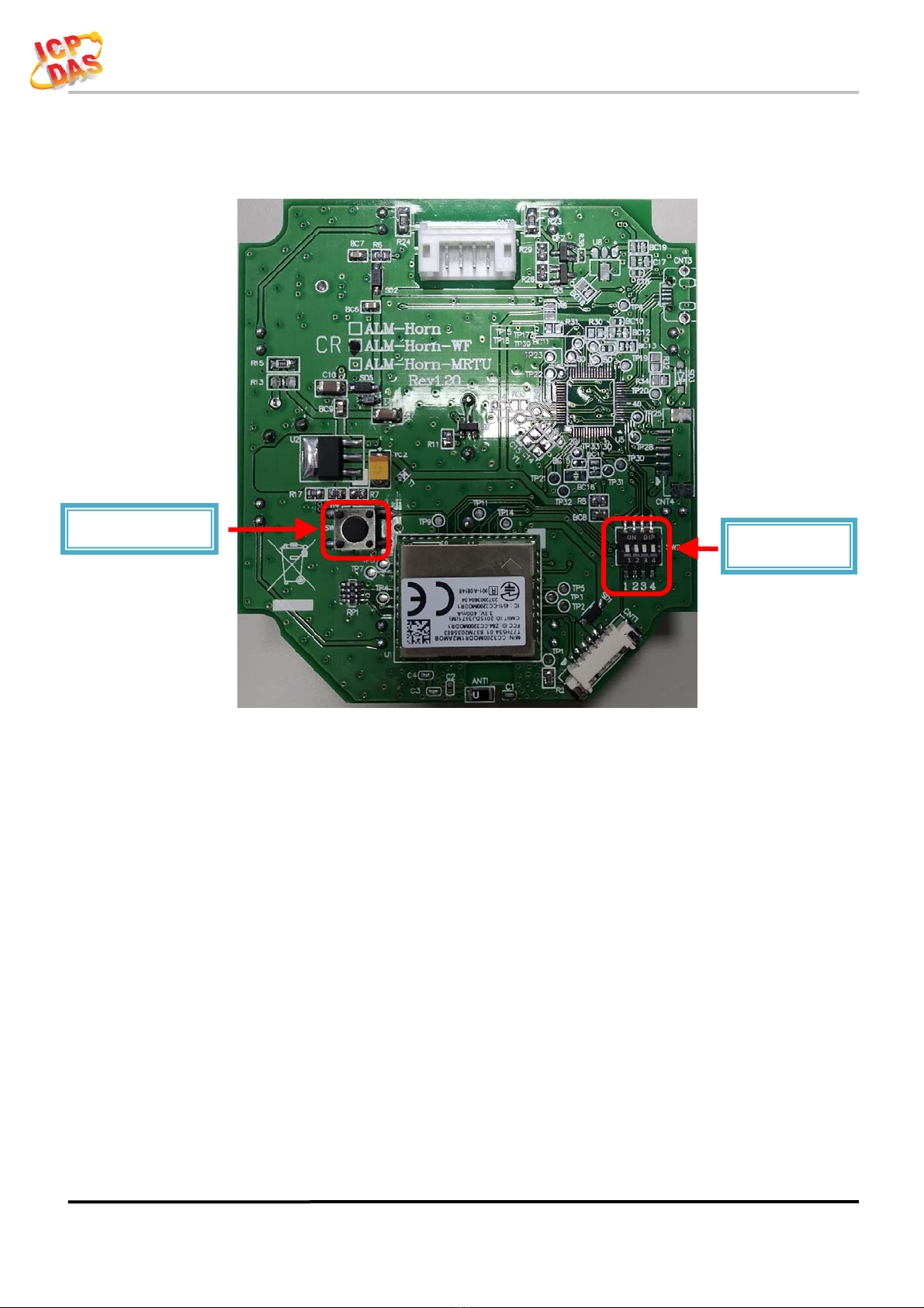
2.2Configuration & Setting .................................................................... 10
2.2.1Reset to default for ALM-Horn-WF(-BR) only ................................. 10
2.2.2Dip Switch Select (All ALM-Horn series) ......................................... 11
2.3Dimensions ....................................................................................... 12
2.4Wire Connection ............................................................................... 13
2.4.1Wire connection define ................................................................... 13
2.4.2I/O connection ................................................................................ 13
3.Software .......................................................................................................... 15
3.1ALM Utility for ALM-Horn-WF(AP Mode) ....................................... 15
3.1.1Main Screen ................................................................................... 15
3.1.2Controller Status ............................................................................... 16
3.1.3DI/DO Status & Control .................................................................... 16
3.1.4Icon Button ...................................................................................... 17
3.1.5Configuration/Setup ....................................................................... 18
3.1.6IP Scanner ..................................................................................... 20
3.2USB Utility for ALM-Horn-MRTU .................................................... 20
4.Modbus Protocol ............................................................................................ 21
4.1.2Function Code .................................................................................. 21
4.1.3Error Response ................................................................................. 21
4.2Data Encoding .................................................................................. 22
4.2.1Binary ............................................................................................. 22
4.2.216-bits Word .................................................................................... 22
4.3Modbus TCP Protocol Description .................................................... 23
4.3.1MBAP ............................................................................................. 23
4.4ALM-Horn-WF/-MRTU Address Mapping ....................................... 24

ALM-Horn Series User’s Manual
ALM-Horn Series User’s Manual (Rev1.0, NOV/2020) ------------- 4
1. Introduction
The ALM-Horn Series include 3 model, -BR with water clean upper cover, ALM-
Horn as standard siren, Blue + Red LED, ALM-Horn-WF have WLAN connection
complies with the IEEE802.11b/g/n standards, support Modbus TCP protocol & HTML,
ALM-Horn-MRTU have RS-485 interface support Modbus RTU protocol.
ALM-Horn series device includes 1-channel digital input for any dry contact output
such as SA, BA, FA ..etc, and 1-channel digital output. Each device has 4 kinds of alarm
tone, NC/NO input mode select by swatches. The ALM-Horn-WF & -MRTU support
Modbus protocol, Which makes perfect integration for monitoring or control in SCADA
software, HMI Modbus & Utility. ALM-Horn series have High Sound Pressure output,
wide input power range & IP43 waterproof
Figure 1-1: Application architecture for the ALM-Horn-WF(-BR)
Figure 1-2: Application architecture for the ALM-Horn-MRTU(-BR)

ALM-Horn Series User’s Manual
ALM-Horn Series User’s Manual (Rev1.0, NOV/2020) ------------- 5
1.1 Features
Standard Alarm Siren or with Wi-Fi, RS-485 interface
Modbus TCP, Modbus RTU protocol
Photo couple input, Open Collector output
Wide power supply range
Wide operating temperature range
Piezo Transducer Output
Water clear upper cover with 8 Ultra-Bright RED LED, or -BR version with 8 Blue +
8 Red Ultra-Bright LED.
4 Selectable Alarm Tone
NC/NO Input Selectable
1.1.1 Features Description
The ALM-Horn series device accepts any dry contact to trigger DI input, when the
alarm been trigger it output from Piezo Transducer, LED’s & open collector DO.
ALM-Horn series include 4 kinds of alarm tone, the DIP switch’s select which tone
when DI been trigger, DIP switch also select the DI trigger mode NC (Normal Close) or
NO (Normal Open).
For Communication device, ALM-Horn-WF/ALM-Horn-MRTU it also accepts
Modbus protocol to monitor DI status and remote trigger 4 kinds of alarm tone
(independent with DI trigger mode DIP switch select).
It has 2 way to make ALM-Horn use as standard siren just supply power without DI
input, one, just switches DI trigger mode to NC (Normal Close), another is short the wire
of DI input with GND.

ALM-Horn Series User’s Manual
ALM-Horn Series User’s Manual (Rev1.0, NOV/2020) ------------- 6
1.2 Specifications
Table 1-1: System Specifications
Device ALM-Horn
(
-B
R
)
ALM-Horn-WF
(
-B
R
)
ALM-Horn-MRTU
(
-B
R
)
Alarm Out
p
ut
Piezo Transducer Pressure Level 120 ± 5 dB @10cm/3.0 KHz (W/O waterproof membrane)
LED Water clear upper cover with Ultra-Bright RED LED x 8
-BR: With 8 Blue + 8 Red Ultra-Bri
g
h
t
LED
Volume Control no
Di
g
ital In
p
ut
Channels 1
Input T
y
pe Dr
y
Contact: Sin
k
Dr
y
Contact Level
N
O: Open, NC: Close to GND
Photo-Isolation 3750 VDC
Input Condition Pulse Width must > 200mSec or more
Di
g
ital Out
p
ut
Channels 1
Output T
y
pe Open Collector (Sink)
Max Load Curren
t
400 mA
Load Volta
g
e +3.5 VDC ~ +30 VDC
Di
p
Switch Select
SW1,2 4 kinds of alarm Tone
SW4 Input Mode (NO/NC) select
Wi-Fi Interface
Interface -
Wi-Fi 2.4G -
Standard Supporte
d
-
IEEE 802.11b/
g
/n -
Wireless Mode -
Station & AP (1 Client) -
Encr
y
p
t
ion -
WEP, WPA and WPA2 -
Service -
TCP, Modbus TCP, HTML -
MRTU Interface
Interface - - RS-485
Pa
r
it
y
/Data bit/ Stop bi
t
- -
N
one/Odd/Even, 8, 1/2
Baud Rate - - 300 ~ 115200 bps
Protocol - - Modbus RTU
Watchdo
g
- - Yes, 1.8s

ALM-Horn Series User’s Manual
ALM-Horn Series User’s Manual (Rev1.0, NOV/2020) ------------- 7
Device ALM-Horn
(
-B
R
)
ALM-Horn-WF
(
-B
R
)
ALM-Horn-MRTU
(
-B
R
)
LED Indicators
Power/Status 2 colors LED, Blue for S
y
stem status, Red for Alarm status.
Protection
Waterproof IP43 (Panel Mount Upright Position)
ESD (IEC 61000-4-2) ±8 kV Air for Random Point
EFT (IEC 61000-4-4) ±2 kV for Power
Environment
Operatin
g
Temperature -20 ~ +75°C
Mechanism
Dimensions(WxLxH) 119mm x 119mm x 48m
m
Installation Panel Mount/Wall Moun
t
Power Re
q
uirements
Input Volta
g
e Ran
g
e 12 ~ 48 VDC with Reverse Protection (Vin to GND)
Consumption 0.4 W Active. 0.7 W Standb
y
.0.48 W Standb
y
.

ALM-Horn Series User’s Manual
ALM-Horn Series User’s Manual (Rev1.0, NOV/2020) ------------- 8
2. Hardware
2.1 Outward Appearance
Figure 2-1: Front Panel
Figure 2-2: Back Panel
Connecto
r
Piezo Transducer output
Waterproof membrane inside

ALM-Horn Series User’s Manual
ALM-Horn Series User’s Manual (Rev1.0, NOV/2020) ------------- 9
2.1.2 Connector Pin Define
Figure 2-3: I/O Connector of ALM-Horn-MRTU(-BR)
Figure 2-4: I/O Connector of ALM-Horn(-BR) & ALM-Horn-WF(-BR)

ALM-Horn Series User’s Manual
ALM-Horn Series User’s Manual (Rev1.0, NOV/2020) ------------- 10
2.2 Configuration & Setting
Figure 2-5: Switches on the PCB
2.2.1 Reset to default for ALM-Horn-WF(-BR) only
Remove the back panel, Press & hold the Reset button on the bottom side
over 6 Sec until the Red LED(Status/Alarm) quick flash then release to restore
device default setting. Default is set in AP mode.
Reset to default Dip Switch

ALM-Horn Series User’s Manual
ALM-Horn Series User’s Manual (Rev1.0, NOV/2020) ------------- 11
2.2.2 Dip Switch Select (All ALM-Horn series)
Figure 2-6: Alarm Tone select switch for DI trigger alarm
Figure 2-7: DI Input Mode (NO/NC) select switch
Note: Change the Input Mode NC/NO must restart the power to take effect.
Dip Switch Switch Index Waveform
0
1
2
3
Dip Switch Switch Input Mode
NO(Normal Open): Short to GND Alarm
NC(Normal Close): Open from GND Alarm

ALM-Horn Series User’s Manual
ALM-Horn Series User’s Manual (Rev1.0, NOV/2020) ------------- 12
2.3 Dimensions
The diagrams below provide the dimensions of the ALM-Horn series to use in
defining your enclosure specifications. All dimensions are in millimeters.
Figure 2-8: Dimension of the ALM-Horn series

ALM-Horn Series User’s Manual
ALM-Horn Series User’s Manual (Rev1.0, NOV/2020) ------------- 13
2.4 Wire Connection
2.4.1 Wire connection define
The following describe the wire color
Figure 2-9: Wire color
2.4.2 I/O connection
2.4.2.1 Digital Input (DI) wiring
Figure 2-10: DI Dry contact wiring

ALM-Horn Series User’s Manual
ALM-Horn Series User’s Manual (Rev1.0, NOV/2020) ------------- 14
2.4.2.2 Open Collector Digital Output(DO) wiring
Figure 2-11: Open Collector Output wiring
2.4.2.3 RS-485 wiring for ALM-Horn-MRTU
Figure 2-12: RS-485 wiring for ALM-Horn-MRTU

ALM-Horn Series User’s Manual
ALM-Horn Series User’s Manual (Rev1.0, NOV/2020) ------------- 15
3. Software
3.1 ALM Utility for ALM-Horn-WF(AP Mode)
The Utility provides the simple way to operating and acquire I/O status. The Utility
can use the wireless network interface to configuration. Provide AP(Access Point) &
STA(Station) mode to connect the ALM-Horn-WF.
ALM Utility available on both Windows & Android application to operating and
configure the ALM-Horn-WF.
Utility Support Windows 7 (or later versions) and Android 5.0 (or later versions).
The following is the main screens provided by Utility, these utility tools can be
thought as a useful tool for configuration and monitoring on the ALM-Horn-WF. It
supplies several functions, such as Monitoring, Control, Connection, Wi-Fi setting and
F/W upgrade, etc…
3.1.1 Main Screen
Figure 3-1: Utility main screen
(Windows Utility , Android App, WEB)

ALM-Horn Series User’s Manual
ALM-Horn Series User’s Manual (Rev1.0, NOV/2020) ------------- 16
3.1.2 Controller Status
Show the connected controller information, user define Locate string, RSSI strength,
Device IP & Static IP button for changing device IP in STA mode.
3.1.3 DI/DO Status & Control
Show the DI/DO status, The value can be read DI or set DO with Tone Index in this
area.

ALM-Horn Series User’s Manual
ALM-Horn Series User’s Manual (Rev1.0, NOV/2020) ------------- 17
3.1.4 Icon Button
ICON function
Setup Open the Setup Screen (Android versions Setup
function under the icon)
Find Controller Red Led blinking, use to find the connected
Controlle
r
Refresh Refresh status
Menu Only Android Device,
Include setup, FW Version & About.
Table 3-1: icon Indicator

ALM-Horn Series User’s Manual
ALM-Horn Series User’s Manual (Rev1.0, NOV/2020) ------------- 18
3.1.5 Configuration/Setup
Figure 3-2: ALM Utility setup page
Click apply icon to save each subject’s setting, after finish all setting click
to make device take effect on new setting
AP:
SSID Name
1. Default Controller’s SSID in Wi-Fi AP mode, will be ALM-06-xxxxxx.
Note: xxxxxx is the last 6 characters MAC address of your device.
Key Type
AP mode SSID Key type (default is Open)
SSID Key
AP mode SSID Key, (default is None)
STA:
SSID Name
Wi-Fi AP’s SSID intent to connect (default is tWFHUB)
Key Type
Wi-Fi AP’s SSID Key Type (default is WPA/WPA2)
SSID Key
Wi-Fi AP’s SSID Key (default is 00000000)

ALM-Horn Series User’s Manual
ALM-Horn Series User’s Manual (Rev1.0, NOV/2020) ------------- 19
Static IP:
IP: Specific an IP that is not been used.
Mask: Default will be 255.255.255.0.
Gateway: Basically define in the AP you are going to connect.
SSID Service Set Identifier: Connected devices must be the same SSID, SSID
len
g
th must not exceed 31 characters.
Key Type
Key of Encryption, connected devices must with the same Key.
Open :No Key request.
WEP(Shared) :Key length must be 15 characters.
WPA/WPA2-PSK :Key length must between 8~15 characters.
Table 3-2: Station SSID & Key type configure
Wi-Fi Mode:
ALM Controller working mode (default is in AP)
AP (Access Point):
PC or Android Device connect to ALM Controller directly through
AP(Fixed IP:192.168.77.1), AP mode support only one connection, If Multiple
devices connect at a same time, only first connected devices can access.
STA(Station):
ALM Controller will auto connect to specific Wi-Fi AP, PC or Android
Device also need to connect to the same AP, then they can use those ALM
Controller in same domain.
*. Please check specific Wi-Fi AP is active and SSID/key is same as the setting
before use.
Location information:
Set the information for you to identify & locate those Controller easily, length
must under 31 characters.
Modbus Port:
Modify Modbus TCP Port (default is 502)
Modbus Idle Timeout:
Set Idle Timeout for Modbus TCP connection (default is 120 Sec) in
STA(Station) mode, recommend 30 Sec. when device in STA mode connect to an
AP, Host device break connect with AP and lost connection, the device will hang in
a dead connection. To prevent this happen, set a timeout, the device will close the
connection and wait for next connect.

ALM-Horn Series User’s Manual
ALM-Horn Series User’s Manual (Rev1.0, NOV/2020) ------------- 20
3.1.6 IP Scanner
There are lots of free IP scanner tools in both Windows & Android OS, for
example “Advanced IP Scanner” for Windows, “Network Analyzer” for Android,
those are high performance scanner tools on each OS.
3.2 USB Utility for ALM-Horn-MRTU
The Utility provides the simple way to configuration ALM-Horn-MRTU via Micro
USB from the device. Include Device Address, Baud Rate, Parity, Data bit length, Stop
bit length. After finish setting, press “Apply” to make device take effect with the new
config.
This manual suits for next models
6
Table of contents