F/N 522803 Jul12 © 2012 ICS, Blount Inc.
814PRO SERVICE MANUAL
7
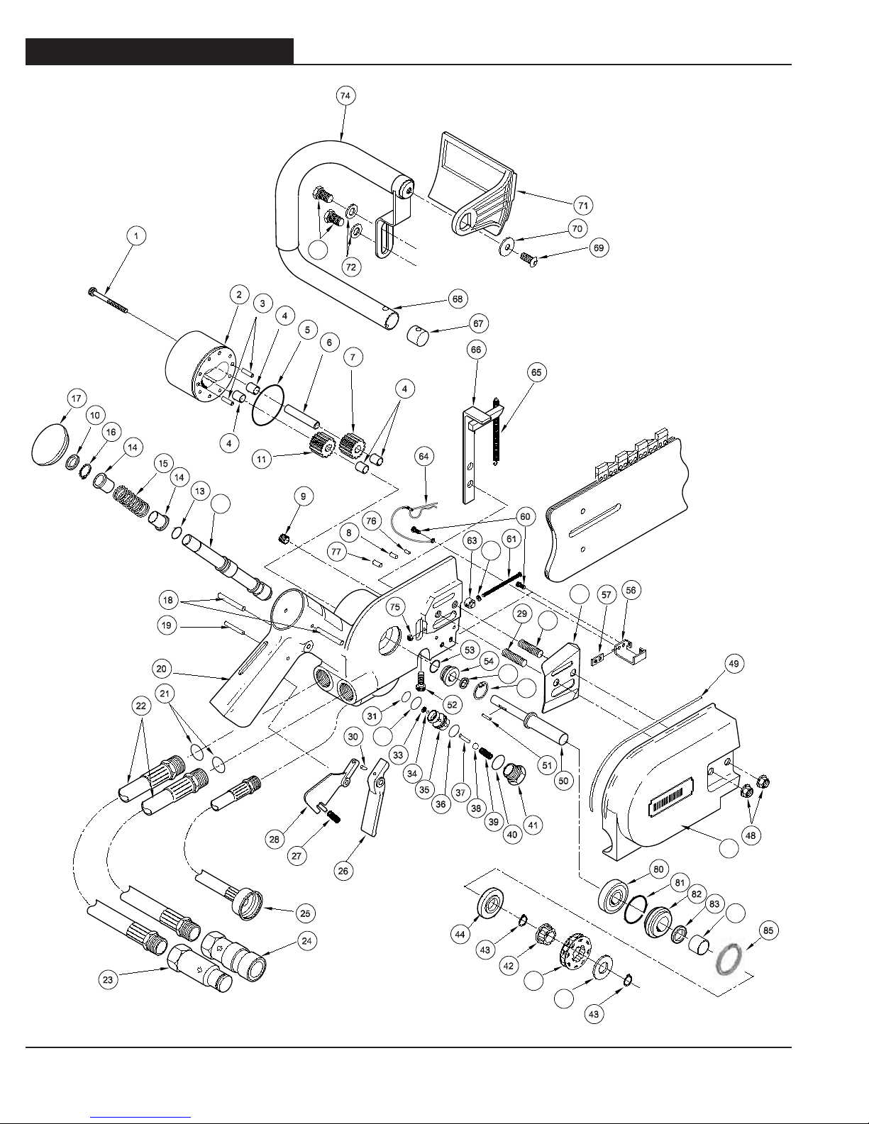
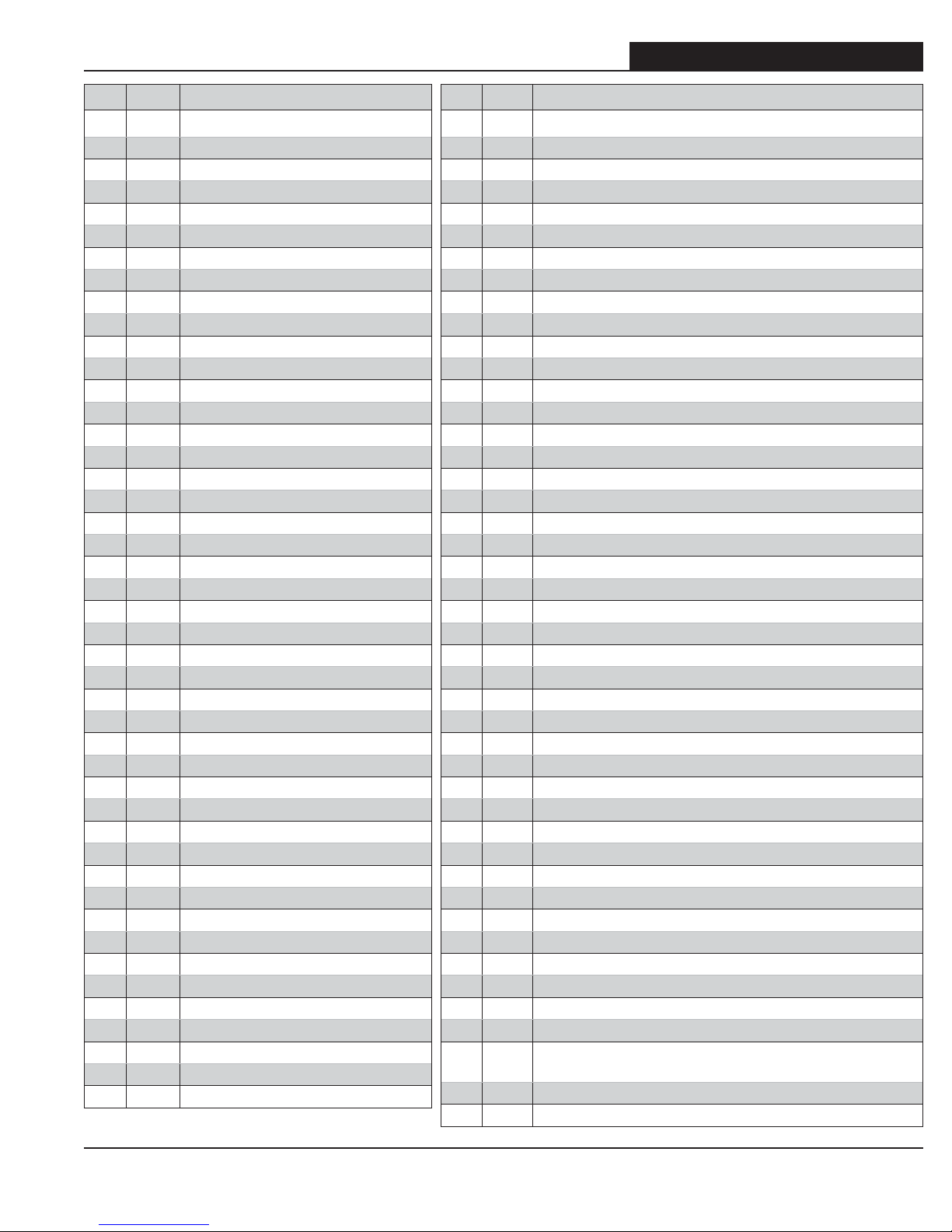
4. SPARE PARTS DIAGRAM
KEY P/N DESCRIPTION
174514 HSH Cap Screw 10-24 x 1 1/4
274515 Rear Gear Housing Assembly
374516 Dowl Pin
474517 Bushing (4)
574518 O-Ring
674519 Idler Shaft
774520 Idler Gear
874021 Wallwalker Pivot Pin
974597 1/8 NPT Plug
10 7459 6 Wiper Seal
11 74522 DriveGear(withKeyway)
12 74523 On-Off Valve
13 74524 Hydraulic Valve Seal
14 74525 Spring Washer
15 74526 Spring
16 74527 Retaining Ring 1/2 External
17 74528 Plug Button
18 74529 Roll Pin
19 74530 Roll Pin
20 74531 Valve Handle Assy (Includes: 31, 66)
21 74532 O-Ring
22 74533 Pigtail Hose Assembly
23 74534 1/2” Flush Face Coupler (M)
24 74535 1/2” Flush Face Coupler (F)
25 74536 Water Hose Assembly
26 74537 Trigger
27 74538 Spring
28 74539 Safety Catch (Trigger Lock-Out)
29 74540 Rear Stud
30 74542 Roll Pin
31 74543 O-Ring
32 74544 O-Ring
33 74545 Self Locking Retaining Ring
34 74546 O-Ring
35 74547 Water Valve Sleeve
36 74548 O-Ring
37 74549 Pin
38 74550 Steel Ball
39 74551 Spring
40 74552 O-Ring
41 74553 Seal Cap
42 71386 Splined Sprocket Adaptor
43 71384 External Shaft Retaining Ring
44 74497 Seal Spacer
45 71385 Rim Sprocket
KEY P/N DESCRIPTION
46 71388 Tabbed Washer
47 71940 SideCoverReplacementKit
48 74558 Flange Nut (M10)
49 74559 Sprocket Side Cover Seal
50 71383 814PRO Motor Shaft Replacement
51 74561 Needle Roller
52 74562 HSH Cap Screw 5/15-18 x 3/4
53 74563 Shaft Seal
54 74564 Seal Back Up Washer
55 74591 Guard Flap Assembly (Not shown)
56 74566 Guard Flap Mount
57 74567 Spacer
58 74568 Bar Mount Cover Plate
59 74569 Front Stud
60 74570 HSH Cap Screw 1/4-20 x 5/8
61 74571 Machine Screw
62 74572 Stat-O-Seal
63 74573 BarAdjustmentNut
64 74019 Lanyard Assembly
65 74582 WallWalker Spring
66 74583 WallWalker Arm (w/ Spring)
67 74574 Handle Bar Retainer
68 74575 Handle Bar
69 74584 Guard Mounting Bolt
70 74585 Guard Mounting Washer
71 74586 Front Handguard
72 74576 Washer
73 74577 HH Cap Screw 5/16-18 x 5/8, Zinc
74 74588 Handlebar Grip
75 74579 Nut 1/4-20 HHD LT SST
76 74580 Spiral Pin
77 74581 Spiral Pin
78 74493 Quad-Ring
79 74565 Retaining Ring
80 74554 Shaft Bearing Race
81 74498 O-Ring
82 74495 Seal Washer
83 74494 V-Ring
84 74496 Seal Ring
85 74555 Retaining Ring
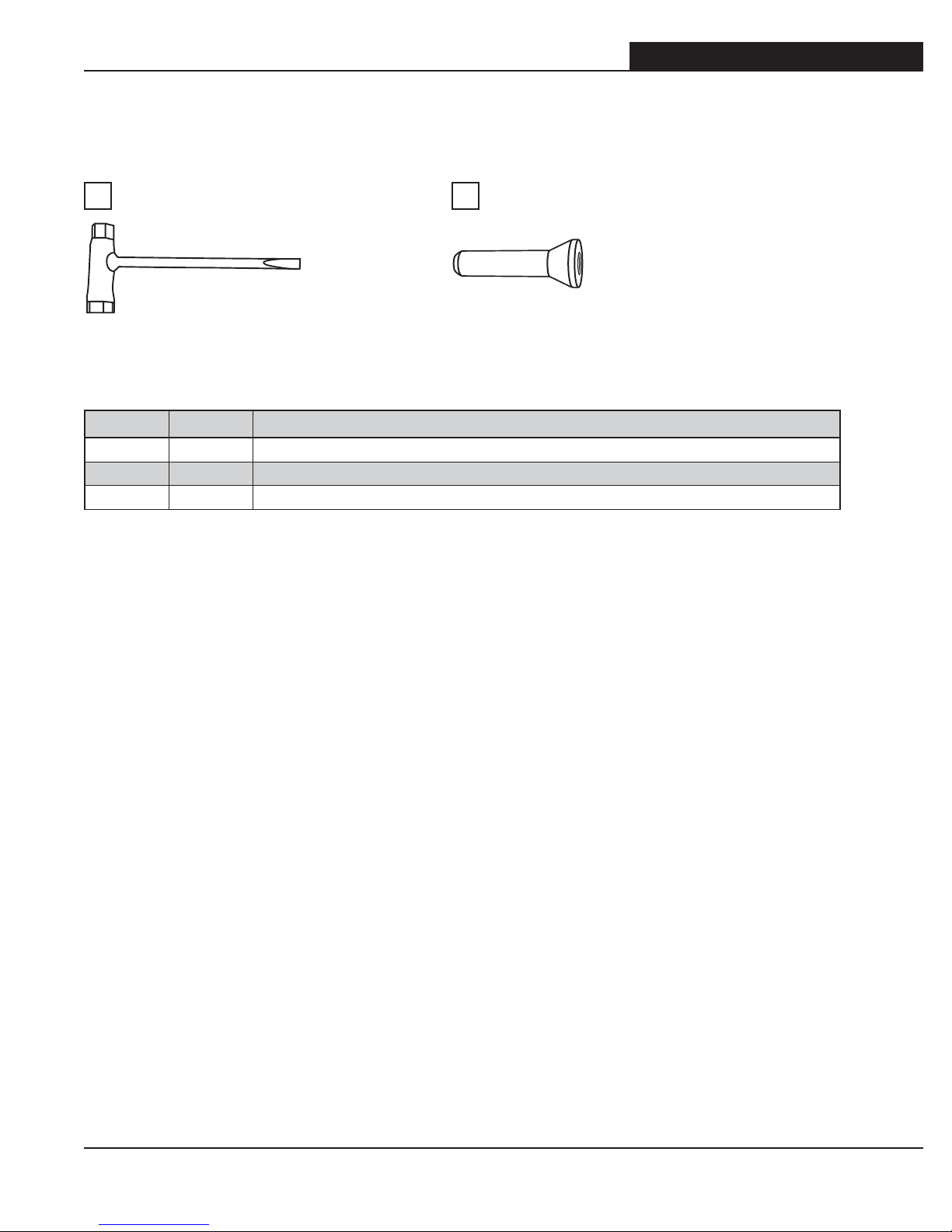
71152 Tensioning Scrench, Hydraulic Saws (not shown)
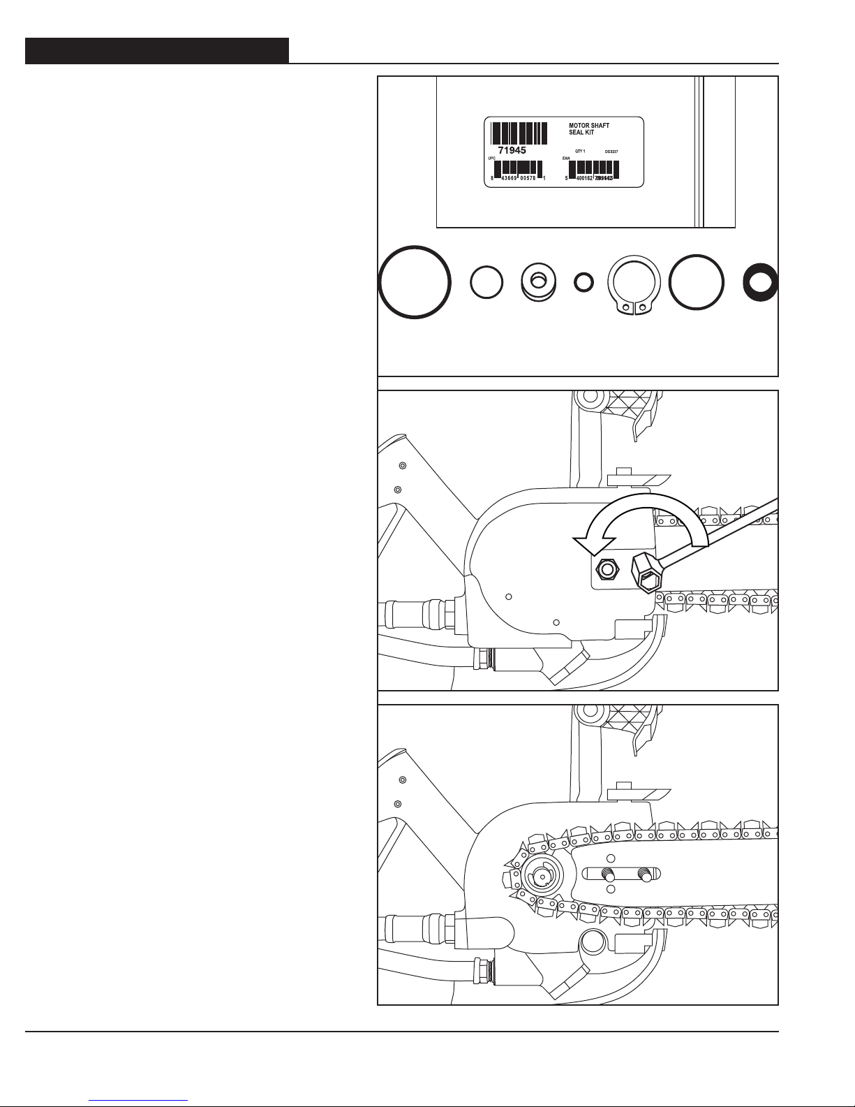
71944 WaterValveSealKit(Incl:31,32,34,36)(notshown)
71945 MotorShaftSealKit(Incl:5,43,53,54,78,81,83)shownon
p.8
74061 Chain Tensioning Assembly (Incl: 61,62,63,75) (not shown)
75260 814RimSprocketUpgradeKit(notshown)