© 2012 ICS, Blount International Inc. Specications are subject to change without notice. REV1112 F/N 70569
TITLE SpeedHook®OPERATOR’S MANUAL
10
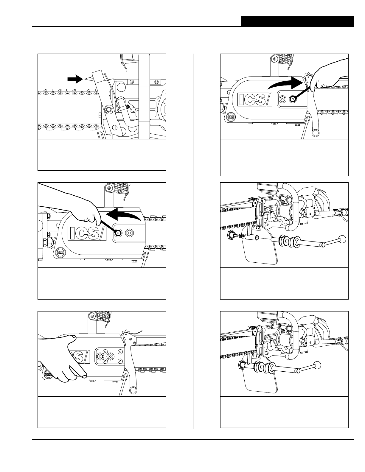
CUTTING TIPS
SYSTEM CLEAN-UP
• Leave the water on and run the saw for 15 seconds with bar tip down to flush slurry and debris
from the system.
• Wash concrete slurry from the saw assembly and SpeedHook®.
• Spray entire SpeedHook®, saw, chain, bar and drive sprocket with a lightweight penetrating oil.
This will minimize rust and reduce slurry build-up on saw assembly.
TIPS FOR CUTTING STRAIGHT
• MOUNTING - Ensure the SpeedHook®rail is securely fastened to the wall, and that the patent
number stamped on centerpiece is facing away from wall. Ensure mounting anchors have not
loosened from the concrete. If the rail becomes loose, SpeedHook® will not cut straight.
• SPACERS - Use 2 to 3 inch (5 to 7 cm) diameter washers to space the rail off the wall especially
when the wall is not perfectly flat. This will reduce warping.
• ANCHORS - Only use anchors approved for mounting wall saws.
• SHORT BAR - Always use the shortest bar possible to cut through the wall. Long bars are
susceptable to deflection, especially when starting the cut.
• STEP-CUT - In hard materials or walls over 8 inches (20 cm) thick, cut as much as you can with
a short bar then switch to a longer bar to finish the cut.
• STARTING THE CUT - Accurately space the rail from the cut and start the cut exactly on
the cut line.
• LONG CUTS - If cut exceeds 42 inches (105 cm), it is possible to stack SpeedHook®rails end to
end.
• FEED PRESSURE - Start the cut using light feed pressure. Be patient, let the saw and chain do
the work. Excessive feed force will cause the bar to deflect and cut crooked.
• AXLE ENGAGEMENT - Keep both bearing surfaces of the axle engaged into the back of the
hooks while cutting. Rotate lever arm 90 degrees to the wall surface until the cams are engaged,
forcing the axle toward the back of the hooks. Support the hydraulic hoses when cutting
horizontally.
• AXLE CAMS - To maximize the life of the cams, avoid engaging the cams against the large
Speedhook®rail anchor washers. The washer's sharp edge will gouge the cams, reducing their
effective life. If possible, avoid the hook that causes interference between the cams and anchor
washers.
• DRESS BAR RAILS - At the first sign of a crooked cut, flip the guidebar over (it's reversable).
Dress the guidebar rails on a belt sander to make the rail height on each side even again.
• UPGRADE SPEEDHOOK - To help cut straighter, with less physical effort, upgrade earlier
SpeedHook®to new axle bracket.