Ideal Boilers touch User manual

Quick start guide
Connected wireless room thermostat
Logic Combi C / Vogue Gen 2 Combi

Introduction
Welcome to the Ideal Touch quick
start guide. This guide is designed to
lead you through a straight forward
installation and setup. It is advisable to
read through all steps before starting
the installation.
A more detailed installation guide, user
guide and FAQs can be found at
www.idealboilers.com.
The Ideal Touch thermostat must be
installed by a competent person.
Read the instructions carefully.
Failure to follow these instructions
can damage the product or cause a
hazardous condition.

3
Ideal Touch Connect kit contents
• Touch thermostat
• Mounting bracket cover
• Boiler transceiver
• Desktop stand
• Mounting bracket
• Batteries (AA)
• Gateway
• Ethernet cable
• Gateway power cable and 3
pin plug
• Screws and plugs
• Quick start guide
• SAP registration label
Getting started
The Ideal Touch app is available to download from the Apple app store and on
Google Play. To save time the householder may want to download the app and set up
the account whilst the thermostat is being installed.
Location guidelines
In-between the boiler and the Touch thermostat and in-between the boiler and the
gateway there must be:
• Less than 20 metres
• No more than 3 walls / ceilings
• No large metallic objects (e.g. American fridge/freezer)
• No large mirrors or windows
• No walls running along the RF path
The Thermostat must not be within 1 metre of a WiFi booster / router and should not
be placed near draughts, in direct sunlight or near heat sources. NOTE. There must be
a free ethernet connection available on the house wireless router and the router must
be a standard household router. A mains socket must be available close to the router.

4
Location guidelines
1m
(min)
Gateway Touch
Wi-fi
booster
Phone
20m
(max)
1m
(min) Gateway
Boiler
The thermostat and the
gateway must be more than 1
metre away from other wireless
devices such as wifi boosters,
cordless phones, and mobile
phones.
The gateway and the
thermostat must be forward of
the front plane of the boiler by
at least 1 metre.
The gateway and the
thermostat must be less than
20 metres from the boiler.
1
2
3
5
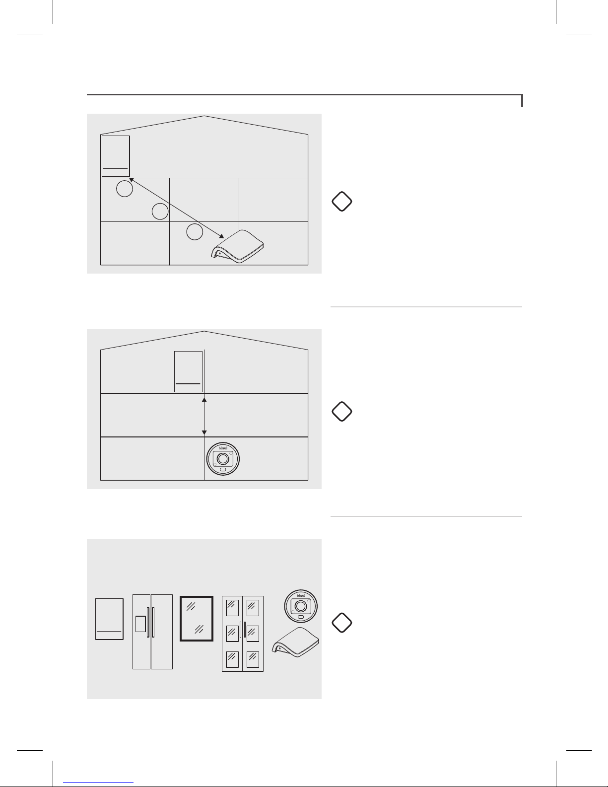
Location guidelines
RF Path
3
2
1There must be no more than
a total of 3 walls and ceilings
between the boiler and the
gateway, and between the
boiler and the thermostat.
There must be no walls running
along RF path from the boiler
to the gateway or the boiler to
the thermostat
There must be no large metallic
objects (e.g. american fridge/
freezer), large mirrors or
windows, between the boiler
and the gateway or between
the boiler and the thermostat.
4
5
6

6
F
U
S
ETurn o the electrical power to
the boiler.
Remove the blanking plate by
carefully inserting a small flat bladed
screwdriver into the slot situated
centrally at bottom of blanking plate.
Remove link wire plug & keep in a
safe place.
Connect the Touch transceiver
electrical plug.
Push fit the Touch transceiver into
the boiler.
Blanking
Plate
Link
Plug
Transceiver
Transceiver
Installation
1
2
3
4

7
Installation
F
U
S
E
Using a flat bladed
screwdriver remove the
back cover from the
Touch thermostat and
insert only 3 batteries.
Immediately insert the
fourth battery into
the thermostat.
Turn electrical power
back on to the boiler.
O
On
Auto
MON 10:20
ZONE1
Hold the thermostat
approx 2 metres away
from boiler.
Locate the gateway adjacent to the
house wireless router and connect
the supplied ethernet cable from
the gateway to the wireless router
as shown.
Connect the Gateway power
cable and 3 pin plug together,
then connect the 3 pin plug to a
convenient mains socket. Note DO
NOT yet power up the gateway.
5 6
7
10
8 9
Ethernet cable white (supplied) Gateway power cable (supplied)
3 pin plug
(supplied)
Gateway (supplied)
Homeowner wireless router
(not supplied)
DO NOT CONNECT
POWER TO THE GATEWAY
AT THIS STAGE

8
O
On
Auto
MON 10:20
ZONE 1
20.5
Set system date
DONE
BACK
01 01 18
20.5
CONNECTING TO
BOILER
20.5
Set system time
DONE
00 00
Wait for the screen shown on the
left to be displayed. (In the unlikely
event that this screen is not shown
within 20 seconds, electrically
isolate the boiler, remove one
battery and repeat from step 8.)
When successfully connected the
screen shown on the left will be
displayed. Set the 24hr clock, then
select “DONE”.
Set the date, then select “DONE”.
If the screen goes blank before
set up is complete, tap the screen
and select MENU to access Help &
Settings to set time and date.
When set up is complete the screen
will go blank.
11
12
13
14
Installation

9
O
On
Auto
MON 06:59
ZONE 1
20.5
O
On
Auto
MON 06:59
ZONE 1
!
!
CONTINUE
Note. if the Touch thermostat is activated for some time, the temperature displayed may rise. This will
return to normal operation once all hand held interaction has ceased.
Ethernet cable white (supplied) Gateway power cable (supplied)
3 pin plug
(supplied)
Gateway (supplied)
Gateway LED
indication
Wireless router
(not supplied)
O
On
Auto
MON 10:20
ZONE 1
Tap screen to wake up
the thermostat.
Immediately power up the gateway, and after the LED initialisation sequence
(approx 1 min) the gateway LED will go green indicating that it has
successfully connected.
16 17
19
Installation
Tap the triangle
to progress.
The display will now
show the home screen.
Tap CONTINUE to
complete setup. Note.
phone number is for
future reference only.
18
15
10
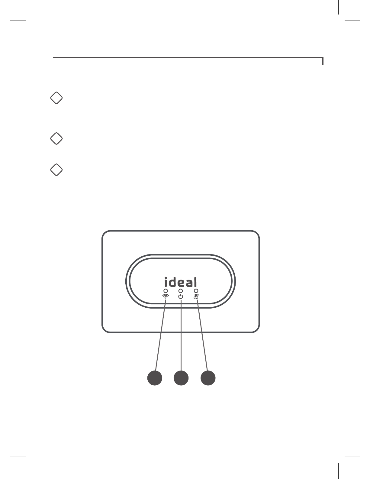
Boiler transceiver
Below are the descriptions of each light on the front of the boiler transceiver.
When illuminated green;
Note. normal operation is indicated by all three green lights being illuminated.
Transceiver
123
RF connection
Boiler transceiver connected to thermostat and boiler
transceiver connected
to gateway
Power
Power is being supplied to the boiler transceiver
Opentherm connection
Opentherm signal to the boiler is working correctly
1
2
3

11
Ideal Touch app
Download and install the Ideal Touch app onto the householders phone.
(Available on Google Play or the Apple app Store.)
A web application is also available at https://app.idealtouch.co.uk
Open the Ideal Touch app, tap on create an account and follow the
in-app instructions.
SN:21182300000001
GATEWAY ETHERNET
MAC: F8:81:1A:Q3:7C:FA
UK - HU5 4JN - National Av
Made in TUNISIA
IP30
CF 527
5V 120mA
PIN : XXXX-XXXX-XXXX
Gateway pin
During app set up the gateway pin will
be requested.
Locate the 12 digit gateway pin on the base
of the gateway, and record the PIN below.

12
Using the Ideal Touch thermostat
Troubleshooting
Rotate to boost
temperature
Tap to change
operating mode
Actual room
temperature
Actual room
temperature
Target room
temperature
Tap to access
main menu
20.5
BACK
?
MAIN MENU
OVERRIDE
HEATING
HEATING
SCHEDULE
HELP &
SETTINGS
Touch thermostat screen is blank after tapping
Check the batteries are inserted correctly.
Replace the batteries in the thermostat.
Heating System does not respond
Make sure the target temperature is at least 1°C higher than the actual room
temperature on the thermostat.
Make sure the heating is not in the OFF mode.
Check the gateway ethernet cable and mains lead are connected properly and the
LED on the side of the gateway status is solid green. If there is no light, check
the mains connection. If the light is solid orange check the ethernet cable is
connected. If the light is solid red consider siting the gateway closer to the boiler.
Check that all of the LEDs on the boiler transceiver are illuminated correctly
(solid green). If the RF light is not illuminated check the thermostat and gateway
have power and are sited as per location guidelines.
Check the boiler has power, if not check circuit breaker and reset if required.
Check the Touch thermostat is within range of the boiler transceiver.
If the Touch thermostat replaced an existing thermostat, ensure the boiler
installer connection link wire is in place (see boiler installation Instructions).
Flame symbol
indicates heating on

13
Warranty
All Ideal Touch Controls oer customers the comfort of a 12 month Ideal warranty,
subject to the following terms and conditions. During the period of the warranty we
will replace free of charge, where it suers a mechanical or an electrical breakdown
as a result of defective workmanship or materials, subject to the following conditions
and exclusions;
The warranty will commence from the
date of installation. Without proof of
purchase the warranty will commence
from the date of manufacture (via
serial number).
The Installation needs to be registered
within 30 days of installation, it can be
registered online by visiting
www.idealboilers.com
If the control suers a mechanical or
an electrical breakdown we should be
contacted on one of the
following numbers:
Northern Ireland: 02890 331444
Elsewhere in the UK: 01482 498660
Our normal working times, excluding
Bank holidays, are:
8am – 6pm Monday to Friday
8am – 4pm Saturday
8am – 12 noon Sunday
The warranty does not apply:
To any defect, damage or breakdown
caused by deliberate action, accident,
misuse or third party interference
including modification or
failed batteries.
To any defect, damage or breakdown
caused by the design, installation
and maintenance of the central
heating system.
To any other costs or expenses
caused by or arising as a result of the
breakdown of the controls.
To any defect resulting from the
incorrect installation of the controls.
To any costs incurred during delays in
fixing reported faults.
Our Ideal Warranty is oered in
addition to the rights provided to
a consumer by law. Details of these
rights can be obtained from a Trading
Standards Authority or a Citizens
Advice Bureau.
Guarantor – Ideal Boilers Ltd, P.O. Box
103, National Avenue, Hull, HU5 4JN.

14

15

Consumer Helpline
T: 01482 498660
Technical Helpline
T: 01482 498663
SCAN HERE FOR FURTHER HELP
For more detailed installation instructions and user guide see www.idealboilers.com
Ideal Boilers Ltd
P.O. Box 103, National Avenue
Hull, HU5 4JN.
www.idealboilers.com
217981 A03
Other manuals for touch
1
Table of contents
Other Ideal Boilers Thermostat manuals


