Ideal Heating EVOMAX 2 30 User manual

When replacing any part on this appliance, use only spare parts that you can be assured conform to the safety and performance
specification that we require. Do not use reconditioned or copy parts that have not been clearly authorised by Ideal Heating.
For the very latest copy of literature for specification and maintenance practices visit our website idealheating.com
where you can download the relevant information in PDF format.
05 / 2023
UIN 233648 A04
PLATE HEAT
EXCHANGER PACKAGE
EVOMAX 2
30 - 150, 30P - 120P

2Plate Heat Exchanger Package
WEEE DIRECTIVE 2012/19/EU
Waste Electrical and Electronic Equipment Directive
• At the end of the product life, dispose of the
packaging
and product in a corresponding recycle centre.
• Do not dispose of the unit with the usual domestic refuse.
• Do not burn the product.
• Remove the batteries.
• Dispose of the batteries according to the local statutory
requirements and not with the usual domestic refuse.
The code of practice for the installation,
commissioning& servicing of central
heating systems

3
Plate Heat Exchanger Package
Ideal Heating reserve the right to vary specication without notice
SAFETY DEFINITIONS
WARNING: Risk of injury or death.
CAUTION: Risk of damage to objects.
IMPORTANT: notes to make you aware.
This kit is suitable for the following boilers:
Evomax 2 30, 40, 60, 80, 100, 120, 150, 30P, 40P, 60P 80P, 100P, 120P
IMPORTANT
THESE INSTRUCTIONS MUST BE USED IN CONJUNCTION WITH THE
LOW OR STANDARD HEIGHT FRAME & HEADER KIT INSTRUCTIONS
SUPPLIED WITH THE EVOMAX HEADERS
CONTENTS
Section 1 - Introduction.............................................................................4
1.1 Introduction.................................................................................4
1.2 General Description....................................................................4
Section 2 - General Description................................................................5
2.1 Plate Heat Exchanger Kit Options ..............................................5
2.2 Hydraulic Separation: Plate Heat Exchanger .............................5
2.3 Output Control ............................................................................5
2.4 Gas Supply .................................................................................5
2.5 Safe Handling .............................................................................5
Section 3 - Package Contents & Components .........................................6
3.1 Package Components ................................................................6
3.2 Plate Heat Exchanger.................................................................6
3.3 Gas Connection Kit.....................................................................6
3.4 PRV Drain Kit..............................................................................6
3.5 Boiler Shunt Pump......................................................................6
3.6 Boiler Flow and Return Pipework ...............................................6
Section 4 - Installation Requirements.......................................................7
4.1 Installation Area and ....................................................................
Dimensions.................................................................................7
4.2 System Requirements ................................................................7
Section 5 - Package Installation ...............................................................8
5.1 PHEX Package Layout ...............................................................9
5.2 Positioning ..................................................................................9
5.3 Levelling......................................................................................9
5.4 Installation Procedure...............................................................10
Section 6 - Electrical Connections & Wiring Diagram.............................11
6.1 Boiler Pump Speed Control via Pwm Output............................11
Section 7 - Commissioning and Testing .................................................12
7.1 Final Checks.............................................................................12
7.1.1 Safety Checks...........................................................................12
7.1.2 PumpConguration..................................................................12
CONTENTS

4Plate Heat Exchanger Package
Section 1 - Introduction
This manual contains information for dimensioning & assembly
of a Plate Heat Exchanger Package for the Evomax 2 range of
commercial boilers.
1.1 INTRODUCTION
1.2 GENERAL DESCRIPTION
This package provides the means to install an Evomax 2 boiler
complete with a plate heat exchanger and associated ancillary
items to separate the boiler hydraulically (primary) from an
existing heating / hot water system (secondary).
See appliance manuals for the ue congurations for the range
of appliances using this kit.
150 kW boilers must be ued following the Clean Air Act.
All headers and pipework should be insulated following the
Non-Domestic Building Services Compliance Guide.
Insulation thickness must be calculated according to BS EN
ISO 12241 using standardised assumptions.
This package is intended for system separation only and must
not be used for instantaneous domestic hot water generation.

5
Plate Heat Exchanger Package
Section 2 - General Description
2.3 OUTPUT CONTROL
The package can be used with an optional accessory boiler
pump, available separately. The package can also be used
with compatible boilers having an internal boiler pump. Pumps
are designed to be wired to and controlled by the appliance to
allow a controlled pump over run.
2.4 GAS SUPPLY
Evomax 2 30, 40, 80, 60, 100, 120 & 150 boilers are
congured for use with natural gas. The 30P, 40P, 60P,
80P, 100P & 120P boilers are congured for use with LPG /
Propane.
The package requires the gas inlet to be made up to the gas
tap provided, connecting it to the appliance's inlet. Assembly
of the gas supply pipework and connection to the gas supply
must follow all the applicable regulations.
A purge valve with a test point is provided before the boiler
gas tap. This test point nearest the appliance gas inlet is
intended to be used as the appliance inlet pressure test point.
2.5 SAFE HANDLING
Take appropriate measures to ensure safe handling of this
appliance, use multiple operatives and or lifting equipment if
necessary.
Operatives should be knowledgeable in handling techniques
when performing these tasks and the following precautions
should be considered:
• Use appropriate handling points
• Be physically capable
• Use personal protective equipment as appropriate, e.g.
gloves, safety footwear
During all manoeuvres and manual handling actions, every
attempt should be made to ensure the following unless
unavoidable and/or the weight is light.
• Keep back straight
• Avoid twisting at the waist
• Avoid upper body/top heavy bending
• Always grip with the palm of the hand
• Use designated hand holds
• Keep load as close to the body as possible
• Always use assistance if required
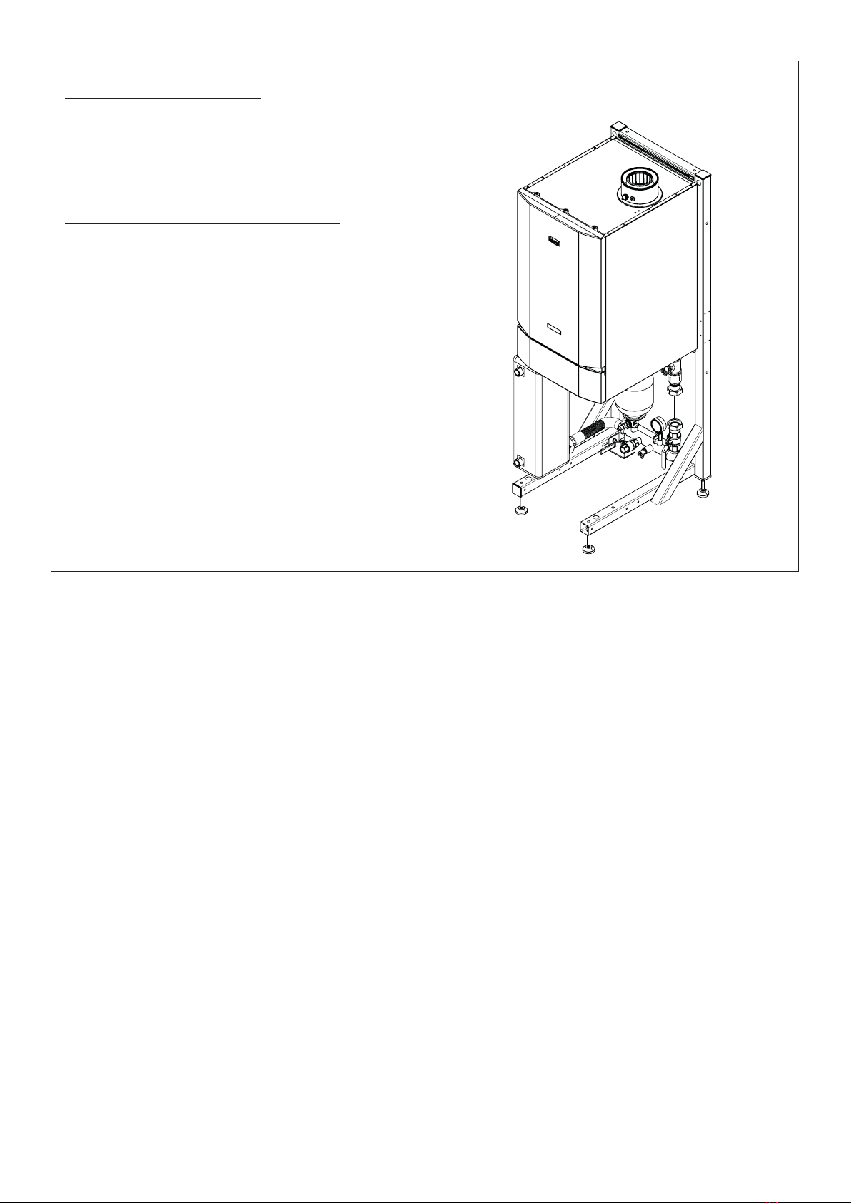
2.1 PLATE HEAT EXCHANGER KIT
OPTIONS
This kit is provided with a plate heat exchanger suitable to
cover a single boiler installation from the range of available
Evomax 2 boilers.
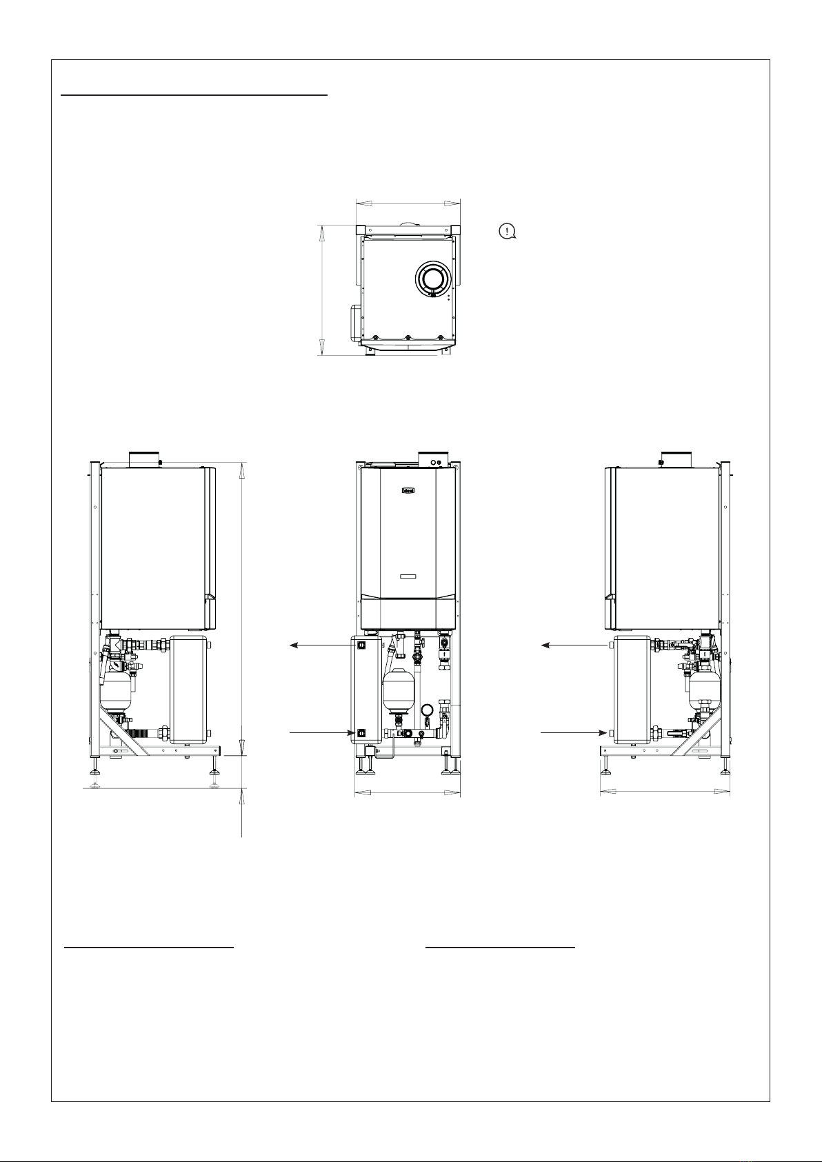
The kit is based on a low height frame and allows hydraulic
separation of the boiler from the secondary system in a
compact envelope.
Consider the modulation range of the appliance and total
heat load requirements when sizing the boiler.
The package and the boiler pumps are intended to operate
with a temperature dierence of 20 °C across the appliance
to provide a 20 °C temperature dierence on the secondary
side of the plate.
Typical boiler and system side operating parameters are
85/65 °C and 75/55 °C respectively.
Available Evomax 2 Appliances
kW (NG) Product No.
Evomax 2 30 220814
Evomax 2 40 220815
Evomax 2 60 220816
Evomax 2 80 220817
Evomax 2 100 220818
Evomax 2 120 220919
Evomax 2 150 220820
kW (LPG) Product No.
Evomax 2 30 Propane 220823
Evomax 2 40 Propane 220824
Evomax 2 60 Propane 220825
Evomax 2 80 Propane 220826
Evomax 2 100 Propane 220827
Evomax 2 120 Propane 220828
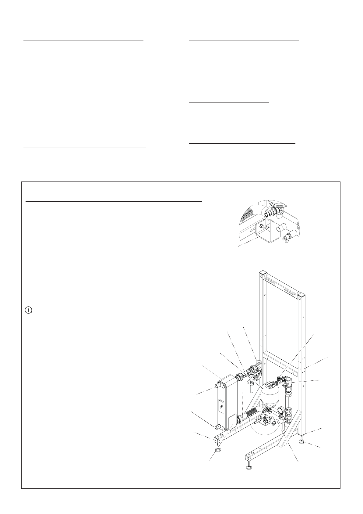
2.2 HYDRAULIC SEPARATION: PLATE
HEAT EXCHANGER
A plate heat exchanger supports hydraulic separation within a
hydronic system allowing two ows to operate independently
with their ow and pressure environments.
The brazed plate heat exchanger used within the package
ensures eective heat transfer and optimum eciency with low
ow resistance and a compact footprint.
The heat exchanger allows hydraulic separation between the
boiler and a heating circuit, covering duties up to 150 kW.
This enables the modern, high eciency condensing boilers
to operate under their optimum conditions, while the adjoining
heating circuit operates to its optimum controlled requirements.
The plate's design is based on standard components and a
modular brazed concept. Each unit is manufactured to the
highest standard and part of the AHRI certied program that
ensures thermal performance under the product specications.
Benets:
• Compact design
• No gaskets
• Easy installed within the plate heat exchanger package
• Low maintenance/ self-cleaning
• All plates are pressure tested during manufacture
CAUTION: Caution should be exercised during these
operations.

6Plate Heat Exchanger Package
Section 3 - Package Contents & Components
3.1 PACKAGE COMPONENTS
The package consist of the following components:
• Frame
• Boiler ow and return pipework
• Boiler gas pipework
• PRV Drain kit
• Plate Heat Exchanger
• Hardware pack (includes essential connections, and
components)
A Boiler Shunt pump MUST be used and is sold separately for
the Evomax 2.
3.2 PLATE HEAT EXCHANGER
The package includes a brazed plate stainless steel plate heat
exchanger sized for all boilers up to 150 kW when operating a
temperature dierential of 20 °C.
3.3 GAS CONNECTION KIT
The gas connection kit consists of 3/4" (19 mm) ttings
suitable for connection to the standard gas tap provided with
the appliance. It also includes a plugged isolation valve with a
combined test point for purging and testing the supplied gas
pressure at the point of connection to the appliance.
3.4 PRV DRAIN KIT
The kit contains solid pipe for the PRV discharge. Ensure the
boiler pressure relief valve is connected and piped to safety.
3.5 BOILER SHUNT PUMP
Boiler pump kits are selected to provide the optimum ow
around the appliance water circuit.
3.6 BOILER FLOW AND RETURN PIPEWORK
001 Gas Connection Kit
002 Mounting Frame Fabrication
003 Evomax 2 Low Height 1.5 in Return
004 50 mm Square Plastic Tube Insert, M12 Threaded
005 Adjustable Foot Ø 50 x M12 x 100
006 Return Manifold Assembly
007 PHEX Cradle Assembly
008 Box End Cap for 50 x 50
009 Return Hose Assembly
010 Secondary Return (1")
011 Secondary Flow (1")
012 Plate Heat Exchanger
013 4L Expansion Vessel
014 Flow Assembly, Heat Exchanger-side
015 Flow Assembly, Boiler-side
016 Return Manifold Support Kit
The connection kit contains the following components:
1. Boiler return leg complete with boiler isolating valve, ll / dosing
isolation valve, pump (supplied separately), non-return valve,
drain cock x2, pressure gauge, expansion vessel, lockshield
valve and bre seals.
2. Boiler ow leg complete with isolating valve, pressure relief valve
and bre seals.
3. Gas leg complete with isolating purge valve with test point, plug,
exible hose.
4. Condensate kit: exi hose for boiler syphon. Fitting, pipework
and exi hose for PRV.
Gas connection: conical adapter, purge valve with test point, tee,
exi-hose.
IMPORTANT: Appliances with an internal boiler pump a
spool piece is provided for the return pipework where the boiler
pump would usually t. Spool piece size G1.1/2 x 180 mm.
001
002
003
004
005
006
007
A
008
009
012
016
013
014 015
Area A
(Components hidden for clarity)
010
011

7
Plate Heat Exchanger Package
Section 4 - Installation Requirements
4.1 INSTALLATION AREA AND
DIMENSIONS
Ensure adequate access for boiler and package installation.
Ensure at least 450 mm clearance from the front of the
appliance to allow servicing.
The condensate drain must have a 1 in 20 fall away from the
appliance.
Adequate room above the boilers must allow the installation
and serving of the boiler ue system. Further information
concerning ue and condensate drain connection can be
found in the boiler installation manual.
4.2 SYSTEM REQUIREMENTS
1. Ancillary components can be connected to the system via
the G3/4” isolation valve on the boiler return pipework.
See diagram below for guidance (diagram for illustration
purposes only).
2. The method of lling, relling, topping up or ushing
sealed primary circuits from the mains via a temporary
hose connection is only allowed if acceptable to the local
water authority.
3. The lling device must be connected to comply with the
water regulations, as shown below. This may involve tting
an a suitable WRAS approved isolator valve to the mains
supply and appropriate backow prevention device.
Pressure relief valve (Supplied with the package)
Pressure Gauge Expansion Vessel
Drain Cock
Return
Double check valve or
RPZ assembly
(note direction of ow)
Additional
stop valve
Hosepipe
(disconnect
after lling)
Water
Supply
Temporary Hose
(disconnect
after lling)
Hose unions
G3/4”
Valve
4. A spring-loaded non-adjustable 3 bar pressure relief valve
complying with the relevant standards of BS6759 Pt1
is tted close to the boiler with no intervening valve or
restriction.
5. A manual testing device.
6. The safety valve outlet should be piped to ensure water or
steam discharge cannot create a hazard to personnel or
damage electrical components or wiring.
Pressure gauge (Supplied with the package)
A pressure gauge covering at least 0-6 bar is tted to the
return pipework, visible from the lling point.
Expansion vessel (Supplied with the package)
7. A diaphragm type expansion vessel complying with BS.
EN 13831 must be tted, with a valve in the normally open
positioned protected using a lockshield from unauthorised
closure.
8. The vessel capacity must be adequate to accept the
expansion of system water when heated to 85 °C.
9. The charge pressure must not be less than the static
water head above the vessel. The pressure attained in the
system when heated to 85 °C should be at least 0.35 bar
less than the lift pressure of the pressure relief valve.
The 4L expansion vessel supplied is suitable for all
appliances.
System drain cock (Supplied with the package)
A drain cock is tted to the lowest section of the return
pipework. A second drain cock is tted above the NRV after
the boiler pump.

8Installation and Servicing
Section 5 - Package Installation
IMPORTANT POINTS
Before commencing installation:
For Frame mounting:
• The frame must stand on a at and level oor of suitable load
bearing capacity.
• The frame must be bolted / secured to the oor after the
connections are made to the boiler or system pipework from the
package to allow for minor adjustments of the position of the
package.
MOUNTING FRAME MUST BE SECURED TO THE FLOOR
These Installations refer to perpendicular walls and oors.
Allowances must be made for installation where skirting boards or
other features are in place that may aect the nominal installation
conditions.

Section 5 - Package Installation
9
Installation and Servicing
5.1 PHEX PACKAGE LAYOUT
557
30-90
1545
685
550
685
5.2 POSITIONING
Careful consideration must be given to the installation
tolerances to prevent kinked or non-tting connections.
If the package is being installed as a retrot to replace an
existing appliance care should be taken to ensure that the
position of the ue connection on the new appliance is
consistent with the existing equipment.
IMPORTANT: Example shown is
for the Evomax 2 150 kW boiler. Note
that the position of the ue connection
for the boiler will vary depending on
the model. Refer to the installation
manual for the appliance.
5.3 LEVELLING
Levelling feet are provided to allow height adjustment
of the package. Height adjustment can be used for
levelling and ensuring that connections to existing ue
systems are correct.
Stainless steel construction of the
plate heat exchanger permits high ow
velocities through plate connections.
Secondary pipework typically requires
increase in size compared to PHEX
connection size to meet guidance on ow
velocities.
Increase from a plate connection should
be created before bends or changes
of direction in secondary pipework.
Pipework on the secondary side of the
plate should be sized by ow rate /
temperature dierential of the secondary
system.
Maximum permissible ow rate through
the secondary side of the plate is 2.8 l/s
producing 41 kPa resistance.
Secondary
Flow (1")
Secondary
Return (1")

Section 5 - Package Installation
10 Installation and Servicing
5.4 INSTALLATION PROCEDURE
Refer to the installation manual for the boiler.
5.4.1 Mounting Frame
Place the frame kit in the required position. Do not secure the
frame to the oor until the installation process has been completed
as adjustments to the position of the frame may be necessary.
5.4.2 Flow / Return Connections
Attach the upper parts of the ow and return connections to the
boiler. Refer to section 3.6
5.4.3 Boiler
Mount the boiler onto the frame kit.
5.4.4 Fitting Gas Connection Kit
Note: Gas Isolation Valve is supplied with the boiler.
1. Fit the conical male adapter to the gas isolation valve.
2. Fit the gas isolation valve assembly to the boiler gas
connection ensuring the sealing washer is tted.
3. Fit the exi gas pipe to the isolation valve.
5.4.5 Condensate Connection
Fit the condensate siphon to the boiler and pipe to drain,
following the recommendations contained in the boiler
Installation instructions.
5.4.6 Pressure Relief Connection
Ensure the boiler pressure relief valve is connected and
piped to safety.
5.4.7 Flow / Return Pipework / Plate Heat
Exchanger
Assemble the remaining sections of the ow and return pipework
to the plate heat exchanger and connect up the boiler circuit.
Where the boiler circuit is circulated by an external pump ensure
that the pump is tted in the correct orientation with ow going
upwards into to the boiler.
Where the boiler has an internal pump ensure that the pump spool
piece is installed.
5.4.8 Filling / Dosing
Fill the boiler circuit to a static pressure of between 1 – 1.5 bar
using the pressure gauge on the boiler circuit pipework. The boiler
circuit should also be dosed with appropriate water treatments as
noted in the boiler installation manual.
It may be necessary to circulate the completed boiler circuit to
purge any residual air from the circuit until a stable pressure
reading is obtained. Ensure that all joints and connections show
no visible signs of leakage.

11
Plate Heat Exchanger Package
Section 6 - Electrical Connections & Wiring Diagram
Refer to the appliance installation manual and iCCS Commercial Control System manual for boiler pump control conguration.
I1 I2 I3 I4 I5 I6 I7 I8 I9 I10
123 1234 12 12 123456 1234 12 123 123456 12345678
L N PE
Fused Spur
/ Isolator
DHW Tank /
Room 2
Room 1
Outside
Temp.
MFR4
PELV
Interlock
Pump control
0-10V
OpenTherm
Header
GND
S4
GND
Mains Supply
Demand inputs
230V 50Hz
Interlock
230V 50Hz
Auxiliary
MFR1
MFR2
MFR3
OT2-
S1
GND
S2
GND
S3
C
OT2+
C
NO
I0
I1
PWM
GND
10V
10V
GND
OT1+
OT1-
NO
PE
C
NO
PE
Mains Voltage/230V 50Hz Volts Free Contacts PELV
L
N
PE
SL1
L
SL2
L
NO
~
~
L
N
C
Boiler Pump Speed Control via PWM output
Note: Refer to the boiler Installation Manual for boiler pump control conguation
Mains Supply External Controls Boiler Pump BMS or Room Control
blue
brown
green/yellow
-
-
-
b
br
g/y
KEY
b
br g/y br
br
b
b
g/y
6.1 BOILER PUMP SPEED CONTROL VIA PWM OUTPUT

12 Plate Heat Exchanger Package
Section 7 - Commissioning and Testing
7.1 FINAL CHECKS
7.1.1 Safety Checks
Electrical and gas safety checks must be carried out
on completion of installation as with individual boiler
commissioning.
UPMXXL for use with Plate Heat Exchangers (1 per boiler)
EVOMAX 2
IMPORTANT: PWM Control to be wired directly to the boiler & MUST be wired in last.
For pump and external pump control wiring refer to this instruction & the boiler Installation Manual.
NOTE: Appliances with internal pumps are pre-wired.
7.1.2 PumpConguration
Pump setting - follow instructions on pump types shown
below.

Notes
13
Plate Heat Exchanger Package

Notes
14 Plate Heat Exchanger Package

Notes
15
Plate Heat Exchanger Package

Technical Training
Our Expert Academy offer a range of training options designed and delivered by our experts in heating.
For details please contact: expert-academy.co.uk
Ideal is a trademark of Ideal Boilers.
Registered Office
Ideal Boilers Ltd., National Avenue, Hull, East Yorkshire, HU5 4JB
Tel 01482 492251 Fax 01482 448858
Registration No. London 322 137
EU Authorised Representative:
Atlantic SFDT
44 Boulevard des Etats-Unis, 85 000 La Roche-Sur-Yon, France
+33 (0)2 51 44 34 34
Ideal Technical Helpline: 01482 498663
Ideal Consumer Helpline: 01482 498660
Ideal Parts: 01482 498665
idealheating.com
Ideal Boilers Ltd., pursues a policy of continuing improvement in the design and performance of its products.
The right is therefore reserved to vary specification without notice.
At Ideal Heating we take our environmental impact seriously, therefore when installing any Ideal Heating product please make sure to dispose of any
previous appliance in an environmentally conscious manner. Households can contact their local authority to find out how.
See https://www.gov.uk/managing-your-waste-an-overview for guidance on how to efficiently recycle your business waste.
This manual suits for next models
12
Table of contents
Other Ideal Heating Industrial Equipment manuals