IDEAL 33-772 User manual

IE Net PRO Cable Tester
Eight modes of operation
1. DATA – cable test mode 5. HUB BLINK
2. COAX (RJ45) – cable test mode 6. Set up Mode
3. LENGTH – Cable length measure 7. OFF
4. TONE 8. Voltage Protection
Press MODE to select any of the seven modes of operation, press SELECT to
enter selected operation mode and proceed,
Press SELECT for two seconds to turn backlight on/off.
DATA – Data Cable Test
1. Press any of the four keys to power on
the tester; when powered on, M12,
M12>RJ45, RJ45 shows on the first
line of the screen;
2. M12 is the default setting; use Up or
Down arrow keys to select M12>RJ45
or RJ45
M12– for 2-pair data cable test
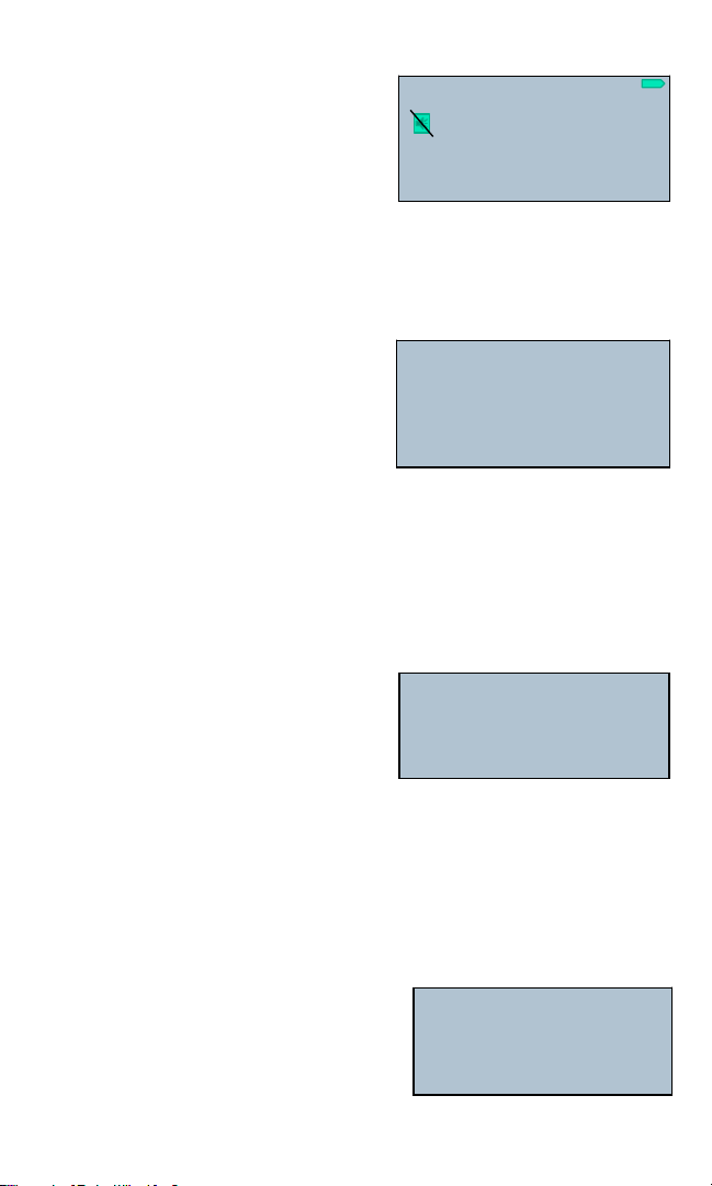
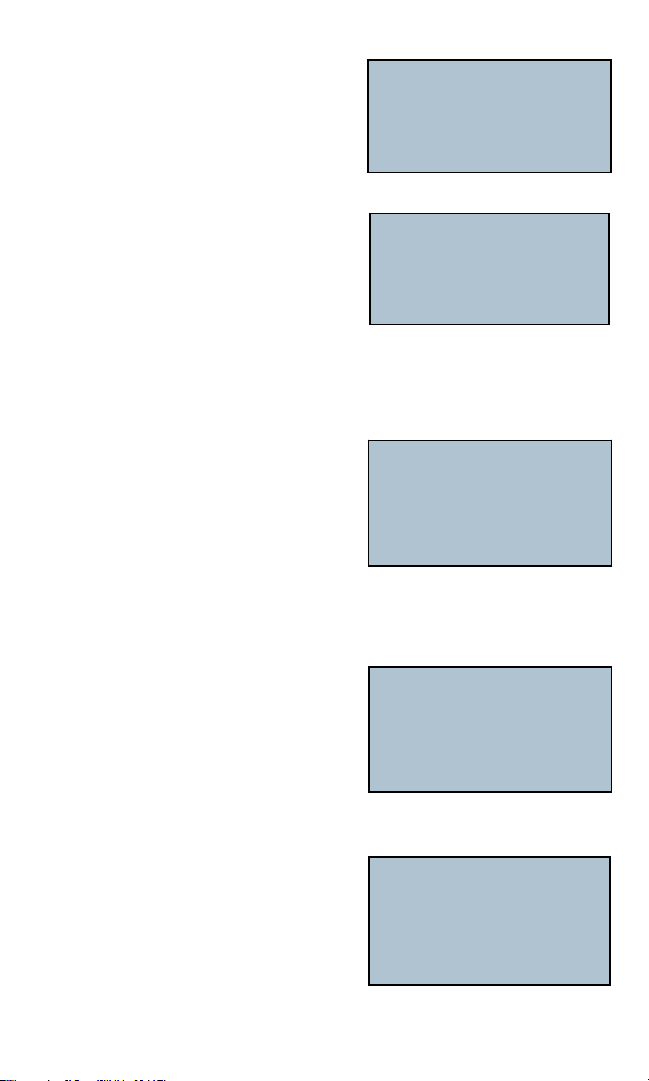
When in M12 mode and no cable is
connected, the display shows:
1. When in M12 mode “No shield” is
default setting
2. Exit to SETUP to change options
(see Set Up mode)
3. When using M12 mode, the Split Pair
function is automatically disabled.
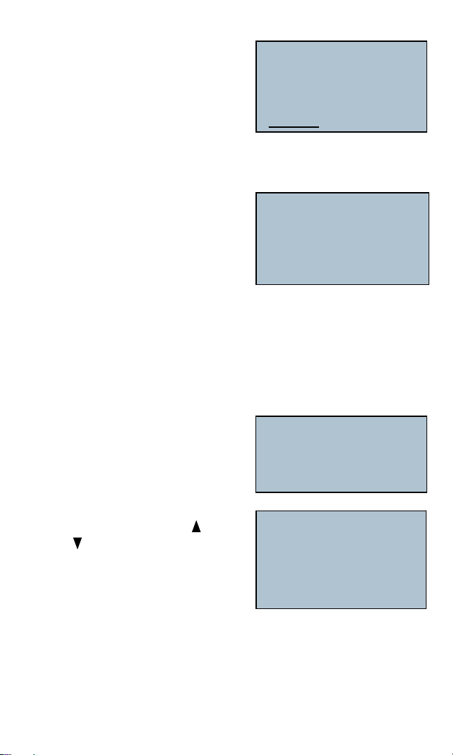
Standby - Cable Test (Pre-Test)
1. When in M12 mode,
2. Connect cable to the Tester (see
following screens for more
demonstrations )
Note: When there is no Remote
connected, Shield and No Shield will
not appear)
33-772
M12 M12>RJ45 RJ45
to change type
MODE=ESC, SEL=go
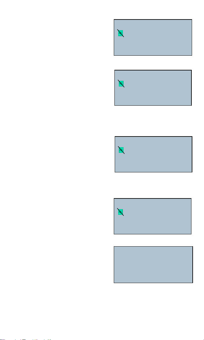
Test M12
1234
Open 1-3 2-4
Displays and cycling in sequential order
1-3, 2-4, No Cable
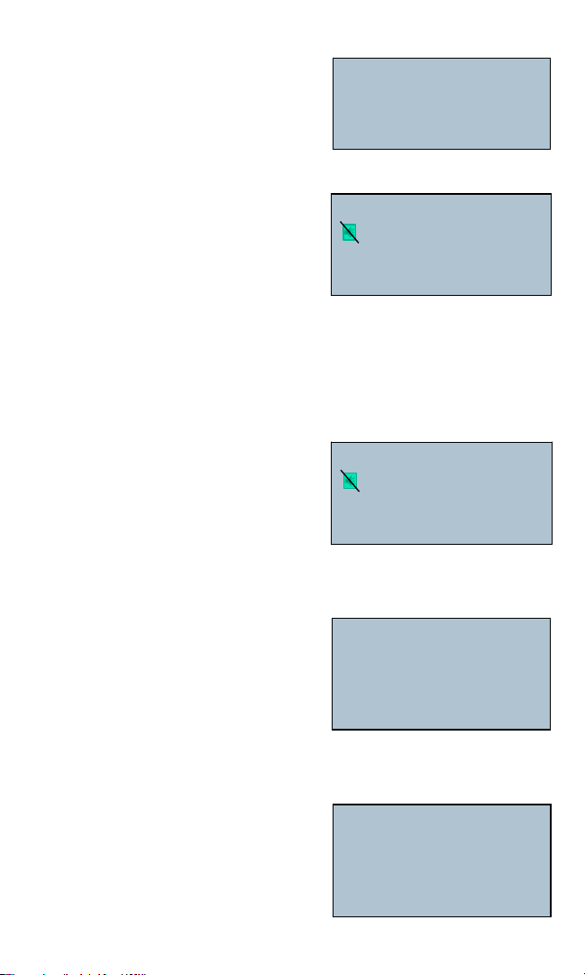
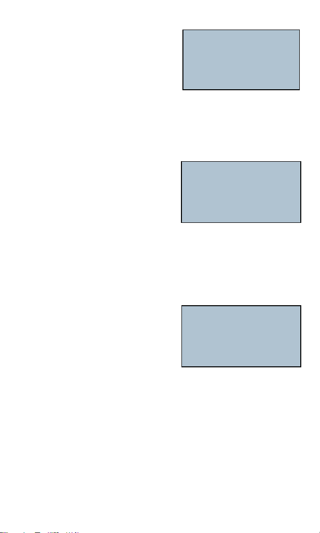
Test M12
12 34
Pass Pre-Test
15.5 ft
Cycling in sequential order
1 2, 3 4

2
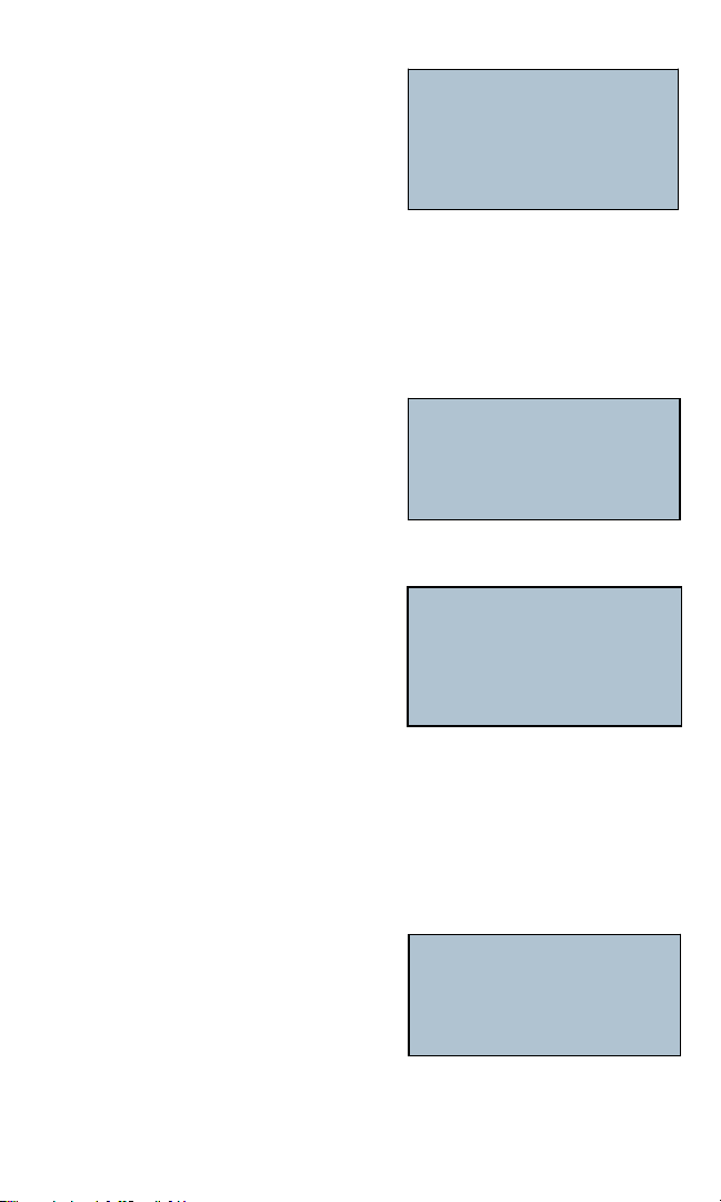
M12 - Setup
To change between shielded & unshielded cable, toggle Beeper to select
length units.
When in SETUP mode -
•UseUporDownarrowkeysandscroll
to Shielded and Unshielded, press
SELECT to change.
•SelectablePassBeep-OnandPass
Beep-Offfunctionisalsoavailablein
this SETUP mode, press Up or Down keys to select and press SELECT to
choose. (Note: Beeper sounds when test passes, and when voltage is
detected on a cable.)
•Inthismode,pressUpandDownkeystoselectbetweenunitsoflength,
Units-feetorUnits-meters,pressSELECTkeytoselect.
M12 – for 2-pair data cable test
Test in Progress - Cable Test
1. When the test is running, “Test” blinks;
when test is completed, “Pass” or “Fail”
shown;
2. Remote ID shown when wire map
passes;
3. The last line shows the length of cable being tested;
4. Beeper icon appears only when Beeper is OFF; low battery icon appears
only when the battery is below 5.5V
Results of a corectly wired shielded cable
1. When the test is running, “test result
shows “Pass”;
2. Remote ID shown when wire map
passes;
3. The last line shows the length of cable
being tested;
4. Beeper icon appears only when Beeper is OFF; low battery icon appears
only when the battery is below 5.5V
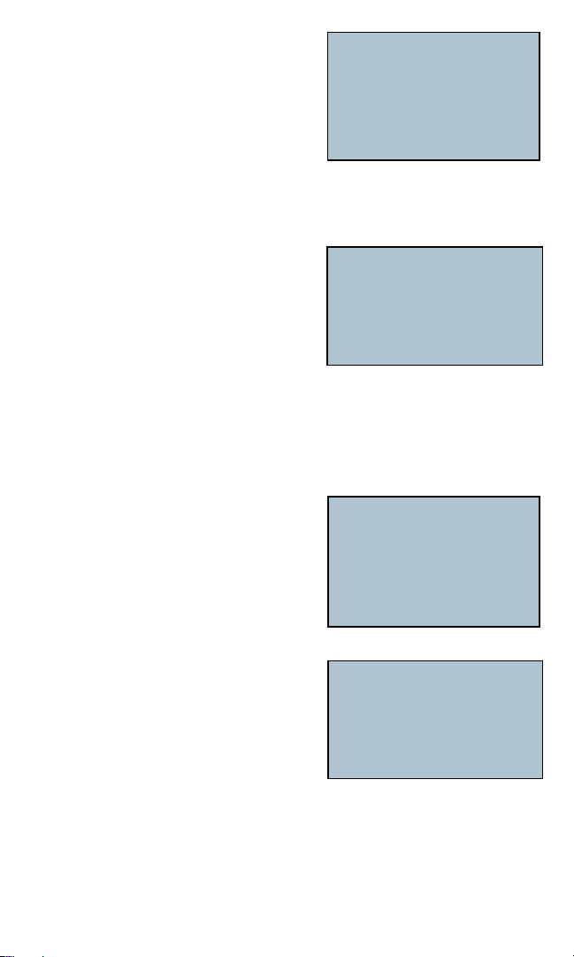
SETUP
Unshielded
SEL to change
Test M12
1234 No Shield
1234 ID 1
1.5m
PASS M12
1234 Shielded
1234 ID 1
1.5m
3
Results of a cross-over, shielded cable
1. “Pass” shown on the first line;
2. Wire Map shows wiring configuration
1324 and ID # indicates the particular
Remote which is in use;
3. “M12 X-Over” displayed on the
last line;
4. Beeper icon appears only when Beeper is OFF; low battery icon appears
only when the battery is below 5.5V
M12 to RJ-45
Cable Test
WheninM12>RJ-45modeandnocable
is connected, the display shows:
1 M12>RJ45 mode
2. “No shield” is default setting
3. Exit to SETUP for more options
(see Set Up mode)
4. When using M12>RJ45 mode, the
Split Pair function is automatically
disabled.
Setup
To change between shielded and unshielded cable, toggle Beeper to select
length units.
WheninSETUPmode-
•UseUporDownarrowkeysandscroll
to Shielded and Unshielded, press
SELECT to change.
•SelectablePassBeep-OnandPass
Beep-OfffunctionisalsoavailableinthisSETUPmode,pressUporDown
keys to select and press SELECT to choose. (Note: Beeper sounds when test
passes, and when voltage is detected.)
•Inthismode,pressUpandDownkeystoselectbetweenunitsoflength,
Units-feetorUnits-meters,pressSELECTkeytoselect.
Standby - Cable Test (Pre-Test)
1.WheninM12>RJ-45mode,
2. Connect cable to the Tester (see
following screens for more
demonstrations)
Note: When there is no remote connected,
shield and no shield will not appear
PASS M12
1234 Shielded
1324 ID 1
M12 X-Over
Test M12>RJ45
1234
Open 1-2 3-6
Displays and cycling in sequential order
1-2, 3-6, No cable
Cycling in sequential order 1 2, 3 4
SETUP
Unshielded
SEL to change
Test M12>RJ45
12 34
Pass Pre-Test
15.5 ft

4
Test in Progress - Cable Test
1. When the test is running, “Test” blinks;
when test is completed, “Pass” or “Fail”
shown;
2. Remote ID shown when wire map
passes;
3. The last line shows the length of cable being tested;
4. Beeper icon appears only when Beeper is OFF; low battery icon appears
only when the battery is below 5.5V
Results of a correctly wired good shielded cable:
1. When the test is running, “test result
shows “Pass”;
2. Remote ID shown when wire map
passes;
3. The last line shows the length of cable
being tested;
4. Beeper icon appears only when Beeper is OFF; low battery icon appears
only when the battery is below 5.5V
Results of a cross-over, shielded cable:
1. “Pass” shown on the first line;
2. Wire Map shows wiring configuration
3162 and ID # indicates the particular
Remote which is in use;
3. “M12>RJ45 X-Over” displayed on
the last line ;
4. Beeper icon appears only when Beeper is OFF; low battery icon appears
only when the battery is below 5.5V
Results of a 2-pair cable, where 1-2 pair found open
1. When a pair of wire was found open,
the two missing pin numbers in line 2
of the wire map indicates the open pair;
2. The last line shows an error message
“Open 1-2”
Test M12>RJ45
1234 No Shield
ID 1
1.5m
PASS M12>RJ45
1234 Shielded
1326 ID 1
1.5m
PASS M12>RJ45
1234 Shielded
3162 ID 1
M12>RJ45 X-Over
Fail M12>RJ45
1234 Shielded
3 6 ID 1
Open 1-2
Results of a 2-pair cable, where 3-6 pair found open
1. When a pair or wire was found, the two
missing pin numbers in line 2 of the
wire map indicates the open pair;
2. The last line shows an error message
“3-6”
Results of a 2-pair cable, where 1, 2 wire of M12 or 1, 3 wire of
RJ-45 found shorted
1. When a single wire was found shorted
with another one, the two missing pin
numbers in line 2 of the wire map
indicates the shorted pair;
2. The last line shows an error message
“Short 13”
Test results of a 2-pair cable, where 3,4 wire of M12 or 2,6 wire of
RJ-45 found shorted:
1. When a single wire was found shorted
with another wire, the two missing pin
numbers in line 2 of the wire map
indicates the shorted pair;
2. The last line shows an error message
“Short 26”
Test results of a 2-pair cable, where 1,2 wire of M12 or 1,3 wire of
RJ-45 found mis-wired:
1. When there is miswire the wire map
shows the pin numbers;
2. An error message “Miswire 13”
appears on the last line.
RJ-45 - for 4-pair data cable test
WhenRJ-45modeisselectedandno
cable is connected, the display shows:
Fail M12>RJ45
1234 Shielded
1 2 ID 1
Open 3-6
Fail M12>RJ45
1234 Shielded
**26 ID 1
Short 13
Fail M12>RJ45
1234 Shielded
13** ID 1
Short 26
Fail M12>RJ45
1234 Shielded
3126 ID 1
Miswire 13
Test RJ45
12345678
Open 1-2 3-6 4-5 7-8
1-2, 3-6, 4-5, 7-8 No Cable
5
6
Standby - Cable Test
1.WheninRJ-45mode,
2. Connect cable to the Tester (see following
screens for more demonstrations) Note:
When there is no remote connected,
shield and no shield will not appear.
Test in Progress - Cable Test
1. Test repeats every 3 seconds (max.);
when test is in progress, “Test” appears
on the first line, when test is completed,
test result “Pass” or “Fail” appears
replacing “Test”;
2. Wire Map shows correct wiring when ID # indicates the particular Remote
which is in use;
3. The last line shows the length of cable being tested;
4. Beeper icon appears only when Beeper is OFF; low battery icon appears
only when the battery is below 5.5V
Test results of an all normal shielded cable with TIA-568-B wiring:
1. “Pass” appears on the first line;
2. Wire Map shows correct wiring when
ID # indicates the particular Remote
which is in use;
3. The last line shows the length of cable
being tested;
Test results of a shielded 4-pair data cable, T-568-B wiring, but a
cross-over cable
1. “Pass” appears on the first line;
2. Third row of screen displays pin numbers
wherecross-overwasdetected;
3. “RJ-45 X-OVER” displayed on the
last line.
Test result of an unshielded 4-pair data cable, standard T-568-B
wiring, No Remote Unit is connected and with 1,3 Shorted, screen
displays as:
1. When test is in progress “Test” blinks;
when test is completed “Test” goes off
and is replaced by “Fail”.
2. Third row of screen displays
”No Remote?”;
3.Errormessages“Short1-3”displayed
on the last line.
Test RJ45
12 36 45 78
Pass Pre-Test
15.5 ft
Cycling in sequential order 1-2, 3-6, 4-5,
7-8
Test RJ45
12345678 No Shield
12345678 ID1
11.5m
Test RJ45
12345678 Shielded
12345678 ID1
11.5m
Pass RJ45
12345678 Shielded
36145278 ID 1
RJ45 X-OVER
Fail
No Remote?
Short 13

7
Test result of an unshielded 4-pair data cable, standard T-568-B
wiring, tested with 4,6 shorted; screen plays as:
1. When test is in progress “Test” blinks;
fault (shorted at 46) was detected, “Test”
goes off and is replaced by “Fail”. The
third row displays ** at pin numbers 4,6
which was the pin or pair found shorted.
2.Errormessage“Short4-6”shownonlast
line replacing cable length.
Test result of an unshielded 4-pair data cable, standard T-568-B
wiring, tested with 1,2 Open:
1. When test is in progress “Test” blinks;
when test is completed, error (Open at
1-2)wasfound,“Test”goesoffand
shows ‘Fail’.
2. The wire map shows two missing pin
numbers indicating the open wire;
3.Errormessage‘Open1-2’appearsonthelastline.
Test result of an unshielded 4-pair data cable, standard T-568-B
wiring, tested with 7-8 pair mis-wired; screen displays:
1. When test is in progress “Test” blinks;
whencompleted,error(mis-wiredat
7-8)wasfound,“Test-”goesoffand
“Failing-’shown.Thethirdrow
displays pins 12345687, in which
78pairwasfoundmis-wired.
Test results of an unshielded 4-pair data cable, with all 8 pins
reversely wired; screen plays:
1. When test is in progress “Test”
blinks; when completed, error was
found, “Test” goes off and “Fail”
appears
2. The third row displays pins
87654321foundmis-wired.
3. The forth row displays error message Miswire 1 2 3 6 , Miswire 4 5 7 8 and
repeats.
Fail RJ45
12345678 No Shield
123*5*78 ID 1
Short 46
Fail RJ45
12345678 No Shield
345678 ID 1
Open 1-2
Fail RJ45
12345678 No Shield
12345687 ID 1
Miswire 78
Fail RJ45
12345678 No Shield
87654321 ID 1
Miswire 1236

8
Test result of an unshielded 4-pair data cable, standard T-568-B
wiring, Remote Unit attached, tested with 1-2, 3 -6 split; screen
plays as:
1. When test is in progress “Test” blinks;
when test is completed, error
(Split 12, 36) was found, “Test” goes off
and is replaced by “Fail”. The third row
displays split pin numbers 1236 and
blinks.
2. Error message “Split 1236” shown on last line replacing cable length.
3. Minimum cable length for testing = 1.0 meter or 3 ft.
Test result of an unshielded 4-pair data cable, standard T-568-B
wiring, Remote #1 in use; tested with 1-2 Opened, 3-6 shorted,
7-8 mis-wired; screen displays multiple errors as:
1. When test is in progress “Test” blinks;
when test is completed and multiple
errors detected, “Test” goes off and is
replaced by “Fail”.
2. On the third row, screen displays pin
numbers*45*87 where errors such as
Open1-2,Short3-6,7-8mis-wiredwere
detected.
3. Multiple errors messages are displayed
on the last row cycling in orders of
severity with Short comes first.
COAX (RJ-45) - Coax Cable Test
1. When in Coax (RJ45) mode, press
SELECT to perform test;
2. The Coax (RJ45) mode is used in
conjunction with eight special numbered
andcolor-codedF-ConnectorsTerminals,
each has its signature that the IE Net Pro can identify.
3. When using Coax (RJ45) mode, the Split Pair function is automatically
disabled.
Fail RJ45
12345678 No Shield
12345678 ID 1
Split 1236
Fail RJ45
12345678 No Shield
4 5*87 ID 1
Short 36
Cycling in sequential order of
Short 36
Open 1-2
Miswire 78
COAX (RJ45)
MODE=ESC, SEL=go

Results of testing a good coax cable, No.5 (Green) Coax Terminator
being used; screen displays as:
1. “PASS” shown on the first line and Coax
(RJ45) mode also shown on first line;
2. On the third line, the remote number and
color code are displayed;
3. When a Remote Terminator is
connected, no length information
will be displayed on the screen.
(when measuring the length of a
coax cable, no remote should be
used, see screen#L-10 of LENGTH
mode)
Results of testing a coax cable without a F-Connector Terminator
attached; screen displays as:
1. “FAIL” shown on the first line and the
Coax(RJ-45)mode;
2. On the third line, “Open” is shown
Note: the eight specially numbered and
color-codedF-ConnectorTerminators
must be used in conjunction with Coax
cable test mode.
Results of testing a shorted cox cable; screen displays as:
1. “FAIL” shown on the first line and the
Coax(RJ-45)mode;
2. On the third line, “Short” is displayed;
LENGTH Mode - Description (1)
•Measuringcablelengthbymeasuringitscapacitanceandusingthecapacitance
per unit of length (length constant) to calculate the length.
•ConnectcabletotheMainunit(withorwithoutthepresenceofaRemoteat
the other end).
•PressanykeytoturnontheTester,pressMODE,scrollthroughandselect
LENGTHmode,pressSELECTkeytoenter(seeScreen#L-1)
• UseUpandDownarrowkeystoselecttypeofcable(M12-2pair
data cable, M12>RJ45 for M12 to RJ45 cable, RJ45 for 4-pair data
cable or Coax (RJ45) for coaxial cable) to test (see screen #L-2),
press SELECT to proceed with cable length measure.
Pass COAX (RJ45)
5 Green
Connect one end of the cable to the main
unit by means of a RJ-45 plug to Coax
Adapter and any one of the eight color
coded Coax Terminators must be
attached on the other end to perform test.
Fail COAX (RJ45)
Open
Fail COAX (RJ45)
Short
9

Data Cable Length Measurement
•Onthistester,M12isdefault,whenitisselecteda5-secondinstantmessage
“select for pair#” appears on the screen; use SELECT key to scroll through
1-2,3-4,autoandselectapairtomeasure.(seescreen#L-3)
•M12>RJ-45comesnext,whenthisdatamodeisselected,useSELECTkeyto
scroll through 12, 36 or auto to select a pair to measure length.
•WhenRJ-45isselecteda5secondinstantmessage“selectforpair#”appears
onthescreen;useSELECTkeytoscrollthrough1-2,3-6,4-5,7-8,autotoselect
apairtomeasurelength.(seescreen#L-4#L-5)
•TheIENet™PROisdefaulttotest1-2pairwhenenteringintolengthmeasure
mode;andifthereisanerrororafaultdetected(seeScreen#L-6)itwillauto-
matically switch to a second pair to carry on the testing.
•ChangelengthconstantbymeansofUpandDownarrowkeys,CALiconis
on when adjusting the constant and goes off when setting is done (see screen
#L-7).
•ExittoSETUPmodetochangeunitoflengthfromfttometer.
Coax Cable Length Measurement
•ConnectcabletotheMainunitbyusinganAdapter(whenmeasuringcoax
cable length, no Remote Terminator is required). Press any key to turn on the
Tester, press MODE, scroll through and select LENGTH mode, press SELECT
keytoenter(seeScreen#L-1)
•When measuring length of a coaxial cable, no remote is required;
1-2 is default pair and must be used for coax length measure.
•UseUpandDownarrowkeystoselectCoax(RJ45)astypeofcabletotest(see
screen#L-10),pressSELECTkeytoproceedwithcablelengthmeasurement
•ChangelengthconstantbymeansofUpandDownarrowkeys,CALiconison
whenadjustingtheconstantandgoesoffwhendone.(Seescreen#L-11)
•Tochangeunitofmeasurementfromfttometer,useSETUPmode.(seescreen
#S-7atSETUPmode)
If the far end of the cable is connected to a Network Device (Hub, Switch, etc.), the
testerwilldisplay“TRingNetwork?”(mostlyonunknowndevices),or“XBase-T
Network?” (when connected to a HUB) or “Network?” (when connected to a
Switch).Seescreens#L-12to#L-14.
Measuring a Data Cable
Screen#L1-LENGTHmode
LENGTH
MODE=next,SEL=go
10
11
Screen #L-2 General Description
1.M12,M12>RJ-45,RJ-45,COAX(R-J45)
shows on the first and second line; Use
Up and Down keys to select, (M12 is
default setting);
2. ID number is displayed only when a
Remote is being used;
3. To change pair measure of other types of
cables, press SELECT to cycle through.
Screen #L-3
1. M12 cable (default) is selected
2. A brief message ‘select a pair #’ appears
on the screen for just 2 seconds
3. Use SEL key to scroll through pairs
(1-2, 3-4, auto), and auto (in this case
3-4pairisselected)
4. If no fault is detected, cable length and
pair number will be displayed.
5. If there is a short, error message will
replace length reading.
Screen #L-4
1. Use Up and Down keys to select
M12>RJ-45 as cable type to measure
length;
2. ID number is displayed only when a
Remote is being used
3. To change pair measure, press SELECT
to cycle through 1-2, 3-6 or auto
Screen #L-5
1. RJ45 is selected;
2. A brief message ‘select a pair #’ appears
on the screen,
3. Use SELECT key to scroll through and
selectapairfrom1-2,3-6,4-5,7-8orauto;
4. If no fault is detected, cable length and pair
number will be displayed;
5. If there is a short, error message will
replace length reading (see next screen #6)
M12 M12>RJ45
RJ45 COAX(RJ45)
Select type to
measure length
MODE=ESC, SEL=go
Displays on third line “Select type to
measure length” repeat cycling
M12 LENGTH
6.0ft 3-4
15.000pF/ft
M12>RJ45
Select type to
measure length
MODE=ESC, SEL=go
RJ45 LENGTH
6.0ft 3-6
15.000pF/ft
12
Screen #L-6
When length measure mode works on a
4-pairdatacableandifashortat1-2pairis
detected; the screen displays as:
1. Whenever there is a short, the fault
message replaces length reading;
Screen #L-7
Change length constant, the screen displays:
1. To change length constant, press Up and
Down keys to adjust pF value,
2. CAL icon is on while adjusting the length
constant, goes off when it is done,
3. Exit to SETUP mode to select unit of length
between ft and meter.
Screen #L-10
To select COAX (RJ-45) as type of cable to measure
1. Use Up and Down arrow keys to select
Coax(RJ45) cable to measure its length;
2. When measuring length of a coaxial
cable, no remote is required;
3. 1-2 is default pair and must be used
for coax length measure.
Screen #L-11
When measuring a good Video (coax) cable length; the screen displays as:
Remarks:
1. If there is a short, the error message
replaces the length reading;
2. To change length constant, press Up and
Down keys
3. CAL icon is on while adjusting the length
constant, goes off when it is done
Screen #L-12
When auto is selected, all the pair wires will
be tested and measured, if the cable is
normal, the screen displays as:
•Measuringacablewhichisconnectedtoa
network device, length reading is shown on
thirdlineandaquestion“T-RingNetwork?”
or“XBase-TNetwork?”apearsonthelastlineofthedisplay.
RJ45 LENGTH
Shorted 1-2
15.000pF/ft
RJ45 LENGTH CAL
0 ft 1-2
16.000pF/ft
M12 M12>RJ45
RJ45 COAX(RJ45)
Select type to measure
length
MODE=ESC, SEL=go
COAX(RJ45) LENGTH
6.0 ft auto
16.250pF/ft
1-2 is default pair for measuring coax cable
length, displays as “auto” on the screen.
RJ45 LENGTH
6.0 ft auto
Xbase-T Network
13
Screen #L-13
Inthiscase1-2istheselectedpairto
measurebut1-2pairisactuallyshorted,the
screen displays:
•Whentestingacablewhichisconnected
to a network device and if the cable has a
shorted pair, then a question “ Network?”,
“T-RingNetwork?”or“XBase-TNetwork?”appearsonthelastlineofthe
display.
Screen #L-14
Ona4-pairdatacable,4-5isthepairofwire
to measure, all normal cable, the screen
displays:
•Measuringacableconnectedtoanetwork
device and if the cable has all the pair wires
shorted, an error message “Out of Range”
will display for a second then followed by a “0 ft” reading; a question “
Network?”,“T-RingNetwork?”or“XBase-TNetwork?”appearsonthelastline
of the display.
•This“OutofRange”phenomenonappearsonlyifthenetworkdevicehasa
inductor coupling which causes a false test result but last just for seconds.
TONE
Tone mode - apply tone to cables,
single or paired wires
To select type of cables to apply tone
1. When in TONE mode, press UP and
DOWN key to scroll through M12,
M12>RJ-45,RJ-45ofCOAX(RJ-45);
press SELECT to select the one to apply
tone
2. Or press MODE and exit to other operation
modes.
RJ45 LENGTH
Shorted 1-2
Xbase-T Network
RJ45 LENGTH
6.0 ft 4-5
Xbase-T Network
TONE
MODE=next,SEL=go
M12 M12>RJ45
RJ45 COAX(RJ45)
Select type to apply
tone
MODE=ESC, SEL=go
14
TONE on M12 cable
1 On the first line, M12 is shown;
2. Selected pairs or pins are shown on the
second line;
3. On the third line, selected tone is displayed.
4. Up & Down keys and Pair or Pin are also
displayed on the last line.
TONE on M12 > RJ-45 cable
1 On the first line, M12 is shown;
2. Selected pairs or pins are shown on the
second line;
3. On the third line, selected tone is
displayed.
4. Up & Down keys and Pair (12,26 or
auto) or Pin are also displayed on the
last line. When sending tone in
M12>RJ45 mode, use the M12 port
ontheIENet™PRO.
TONE on a 4-pair data cable
1.Onthefirstline,RJ-45isshown,atone
isreadytoapplytoa4-paircable;
2. Selected pairs or pins are shown on the
second line;
3. On the third line, selected tone is
displayed.
4. Up & Down keys and Pair or Pin are
also displayed on the last line.
M12 TONE
1234
SEL Hi Tone
Pair or Pin
Press Up and Down arrow keys to select
pairs or pins to apply tone.
Press SEL key to choose any of the four
tone sounds: Tone 1, Tone 2, Hi Tone, Lo
Tone (choose Hi on pair and Low on pin).
Press Up and Down arrow keys to select
pairs or pins to apply tone.
Press SEL key to choose any of the four
tone sounds: Tone 1, Tone 2, Hi Tone, Lo
Tone (choose Hi on pair and Low on pin).
Press Up and Down arrow keys to select
pairs or pins to apply tone.
Press SEL key to choose any of the four
tone sounds: Tone 1, Tone 2, Hi Tone, Lo
Tone (choose Hi on pair and Low on pin).
M12>RJ45 TONE
1234
SEL Hi Tone
Pair or Pin
RJ45 TONE
12345678
SEL Hi Tone
Pair or Pin
15
TONE on coax (video) cable
1.Onthefirstline,COAX(RJ-45)isshown,
a coax cable is ready to accept a tone;
2. On the second line Selected pins are
shown;
3. On the third line, selected tone is
displayed.
4. Up & Down keys and Pair or Pin are also
displayed on the last line. When sending
tone in the COAX (RJ45) mode, use the
RJ45 port on the IE Net PRO with the
included RJ45 to BNC adapter.
HUBBlink
HUBBlinkmodeselected
IENet™PROcabletesterworksonaHUBoraSwitch
1. Connect Tester to a HUB or Switch by
means of a jumper cable;
2. Press MODE to select HUB BLINK and
press SELECT to enter,
3. The Tester sends a link pulse to the NIC
for 3 seconds and stops sending for
another 3 seconds interval, making a cycle time of 6 seconds in total.
4. When sending pulse, the tester displays ‘Test’ and goes off when not sending.
5. When the HUB is receiving the pulse, the indicator light of responsive port
blinks.
Setup Mode
When in Setup mode
Three selectable options:
•ToselectbetweenShieldedand
Unshielded,
•ToselectbetweenPassBeep-Onand
PassBeep-Off(Note:Beepersoundswhen
test result is normal or when a cable carries voltage),
•Tochangeunitsoflength,Units-feetorUnits-meters.
Press Up and Down arrow keys to configure
PS, P, S to apply tones.
Press SEL key to choose any of the four
tone sounds: Tone 1, Tone 2, Hi Tone, Lo
Tone (choose Hi on pair and Low on pin).
COAX(RJ45) TONE
PS
SEL Hi Tone
Pair or Pin
HUB BLINK
MODE=next,SEL=go
Test
HUB BLINK
SETUP
MODE=next,SEL=go

16
#1 Beeper-On and Beeper-Off
1. When in SETUP mode, use Up or Down
arrow keys scroll to Pass Beep On or Pass
Beep OFF, press SELECT key and set;
2. Press MODE and exit to other operation
modes;
3. Message “SEL to change” shown on the
last line.
To select in between Shielded and
Unshielded Cable:
1. When in SETUP mode, use Up or Down
arrow keys scroll to Shielded or
Unshielded, press SELECT key to set;
2. Press MODE and exit to other operation
modes;
3. Message “SEL to change” shown on the last line;
To change units of length measure from ft. to meter
1. When in SETUP mode, use Up or Down
arrowkeysandgotoUnits-FeetorUnits-
Meters setting, press SELECT key to set;
2. Up and Down arrows, units of length are
shown on the third line;
3. Message SEL to change shown on the
last line;
4.DefaultsettingisUnits-Feet
OFF Mode
PowerON/OFF,autoshutdownandbacklight
•TheIENet™PROTestercanbepoweredon
by pressing any of the four key buttons.
•TheIENet™PROTesterpowersoff
automatically after 5 minutes of continuous
testing of a single cable
•Mostpower-onmodeswilltimeoutin
20minutes;Tonemodetimesoutafter2-1/2hours.
•TheTesterwillturnoninthelastmodeusedbeforeitwasturnedoff.
•SwitchonbacklightbypressingSELECTbuttonfor2seconds,
•Thebacklightturnsoffautomatically3minutesafterbeingturnedon(withor
without test activity)
SETUP
Pass Beep ON
SEL to change
SETUP
Unshielded
SEL to change
SETUP
Units-Feet
SEL to change
OFF
MODE=next,SEL=go

17
Voltage Protection
Monitoring voltage presence when operating cable test or cable
length measure
1. “VOLTAGE!!” appears on third line of the
screen and tone sounds continuously
(for Voltage 2.2V or above).
VOLTAGE!!

18
Probador de Cables IENet™ PRO
Eight modes of operation
1.DATOS-mododepruebadecable 5.PARPADEODELHUB
2.COAX(RJ45)-mododepruebadecable 6.Mododeconfiguración
3.LONGITUD-medicióndelalongituddelcable7.OFF
4. TONO 8. PROTECCIÓN DE VOLTAJE
Presione MODEparaseleccionarunodelosochomodosdeoperación,pre-
sione SELECTparaingresaralmododeoperaciónseleccionadoyproceder,
Presione SELECT durante dos segundos para apagar o prender la luz de fondo.
DATOS - Prueba de cables de datos
Presione una cualquiera de las cuatro teclas
para encender el probador; cuando se
enciende aparecen en la primera línea de la
pantalla M12, M12>RJ45, RJ45;
M12eslaconfiguraciónpredeterminada;
use las flechas Arriba o Abajo para seleccionar M12>RJ45 o RJ45
M12 - para prueba de cable de datos de 2-pares
Cuando está en modo M12 y no hay
cable conectado, la pantalla muestra:
1. Cuando se encuentra en modo M12,
“No shield” (Sin blindaje) es la
configuraciónpredeterminada
2. Salga al SETUP para cambiar las
opciones(vermododeConfiguración-
Setup)
3.CuandoseusaelmodoM12,lafuncióndePardivididosedesactiva
automáticamente.
Prueba de cable (Pre -Prueba)
Cuando está en modo M12,
Conecte el cable al Probador ( ver las
siguientes pantallas para mas ejemplos )
Nota: cuando no hay un Remoto
conectado, no aparecerán Shield y no
Shield)
33-772
M12 M12>RJ45 RJ45
to change type
MODE=ESC, SEL=go
Test M12
1234
Open 1-3 2-4
Los visualiza y los rota en orden secuencial
1-3,2-4, Sin Cable
Test M12
12 34
Pass Pre-Test
15.5 ft
Rotando en orden secuencial
1 2, 3 4

1919
Configuración - M12
Para cambiar entre cables con o sin blindaje, active el Beeper para seleccionar
las unidades de longitud.
Cuando se encuentre en el modo de configuración - SETUP -
•Uselasflechasdedesplazamiento
Arriba o Abajo para elegir entre Con o
Sin blindaje, presione SELECT para
cambiar.
•EnestemododeSETUPsepuede
seleccionartambiénlafunciónPassBeep-onyPassBeep-off(sonidoon/
off al pasar la prueba), presione las teclas Arriba o Abajo para seleccionar y
presione SELECT para escoger. (Nota: el Beeper suena cuando la prueba es
exitosa y cuando se detecta voltaje en el cable.)
•Enestemodo,presionelasteclasArribaoAbajoparaseleccionarentre
unidadesdelongitud,Unidades-PiesoUnidades-Metros,presioneSELECT
para seleccionar.
M12- Prueba en Progreso para
prueba de cable de datos de 2-pares
- Prueba de Cable
1. Cuando la prueba esta corriendo,
“Test” parpadea; cuando la prueba se
completa,aparece“Pass”sipasóo“Fail”
si fallo.
2. Se muestra la ID remota cuando el mapa del cableado pasa la prueba;
3. La última línea indica la longitud del cable que se está probando;
4. Aparece el icono del Beeper solamente cuando el Beeper está OFF; el icono
de baja batería aparece solamente cuando la batería está por debajo de 5.5V
Resultados de un cable blindado correctamente alambrado
1. Cuando la prueba está corriendo, el
resultado de la prueba indica “Pass”;
2. Se muestra la ID remota cuando el mapa
de cableado pasa la prueba;
3. La última línea indica la longitud del
cable que se está probando;
4. Aparece el icono del Beeper solamente cuando el Beeper está OFF; el icono
de baja batería aparece solamente cuando la batería está por debajo de 5.5V
SETUP
Unshielded
SEL to change
Test M12
1234 No Shield
1234 ID 1
1.5m
PASS M12
1234 Shielded
1234 ID 1
1.5m
2020
Resultados de un cable blindado cruzado.
1. Pass” se indica en la primera línea;
2. El Mapa de cableado muestra la
configuración1324 y el # ID indica el
Remoto particular que está en uso;
3. Aparece “M12 X-Over” (M12
cruzado) en la última línea;
4. Aparece el icono del Beeper solamente cuando el Beeper está OFF; el icono
de baja batería aparece solamente cuando la batería está por debajo de 5.5V
Prueba de Cable M12 a RJ-45
Cable Test
Cuando se encuentra en modo M12 >
RJ-45ynohayningúncableconectado,
la pantalla indica
1. modo M12 >RJ45
2 Laconfiguraciónpredeterminadaes
“No shield”, es decir sin blindaje.
3. Salga al SETUP para más opciones
(Ver el modo Setup)
4.CuandoseusaelmodoM12>RJ45,lafuncióndePardivididosedesactiva
automáticamente.
Setup (Configuración)
Para cambiar entre cable con o sin blindaje, alterne el Beeper para seleccionar
las unidades de longitud.
Cuando está en el modo de
configuración-SETUP-
•Uselasflechasdedesplazamiento
Arriba o Abajo para elegir entre Con o
Sin blindaje, presione SELECT para cambiar.
•EnestemododeSETUPsepuedeseleccionartambiénlafunciónPass
Beep-onyPassBeep-off,presionelasteclasArribaoAbajoparaseleccionar
y presione SELECT para escoger. (Nota: el Beeper suena cuando la prueba
es exitosa y cuando se detecta voltaje en el cable.)
•Enestemodo,presionelasteclasArribaoAbajoparaseleccionarentre
unidadesdelongitud,Unidades-PiesoUnidades-Metros,presioneSELECT
para seleccionar.
Standby - Prueba de cable (Pre -Prueba)
1. Cuando se encuentre en el modo
M12>RJ-45,
2. Conecte el cable al Probador ( ver las
siguientes pantallas para mas ejemplos )
Nota: cuando no hay un Remoto
conectado, no aparecerán Shield y no
Shield
PASS M12
1234 Shielded
1324 ID 1
M12 X-Over
Test M12>RJ45
1234
Open 1-2 3-6
Visualiza y rota en orden secuencial 1-2,
3-6, Sin cable
Rotando en orden secuencial 12, 3 4
SETUP
Unshielded
SEL to change
Test M12>RJ45
12 34
Pass Pre-Test
15.5 ft
Table of contents
Languages:
Other IDEAL Cable Tester manuals


