Reflex variomat 1 User manual

reflex ’variomat’
Pressure-maintaining station
Assembly, operating and
maintenance instructions
Status 03/07

General
Overview, type key for control unit 3
Control panel 4
General safety instructions 5
Assembly
Scope of delivery 6
Installation site 6
Installation of the ’variomat’ control unit 7
Installation of the VG basic vessel 7
Installation of the VF secondary vessel 8
Assembly of the add-on parts for VG and VF vessels 8
Assembly of the level gauge at the VG basic vessel 9
Assembly of the VW thermal insulation 9
Connecting the control unit, expansion lines 10
Assembly diagrams 11 – 12
Electrical connection 13 – 15
Soft start 15
Initial start-up
Prerequisites for start-up 16
Start routine 16 – 17
Filling the vessels and control unit 18
Bleeding the pumps 18
Automatic operation 19
Cleaning the dirt traps 19
Operation
Automatic mode 20
Manual mode 20
Stop mode 20
Customer menu 21 – 22
Service menu 23
Default settings 23
RS-485 interface 24
Messages 24 – 25
Maintenance, inspection, disassembly
Maintenance instructions 26
Disassembly 27
Inspection prior to start-up 27
Inspection intervals 27
General description
Mode of operation 28 – 29
Operating parameters 29
Dimensions, weights 30
Reflex Service 31
Certificate numbers 31
Declaration of conformity 32
Assembly, maintenance and commissioning certificate 33
reflex ’variomat’
Table of contents

1 Cap ball valve Rp 1 (obscured)
to the pump pressure line
2 Pressure transducer
3 Solenoid valve (make-up)
4 Dirt trap
5 Cap ball valve Rp 1 to the
overflow line
6 Motorised ball valve
7 Non-return valve
8 Pump
9 Evacuation device (pump,
obscured)
10 Safety valve
’variomat 2-1’
control unit
VG basic vessel
Close-up of the ’variomat’
Technical version
Number of pumps
Pump type
’variomat 2 - 1/ 60’
’variomat 2 - 2/ 75’
’variomat 1’ (only 1 pump and one type)
Circuit water overflow line
Make-up water
Circuit water pump line
POWM
reflex ’fillset’
(accessory)
16 Level gauge (oil cell)
17 Filling and draining tap
18 Connection for VF secondary
vessel up to 1000 l ∅= 740 mm
19 Dipstick-tube degassing unit
20 Opening for air compensation
between vessel wall and
diaphragm (compensating
bend)
21 Diaphragm
22 VG basic vessel
Escape line
O
10
Type key for control unit
2
4
11
13
12
615 16 17
2
8
21
20
19
22
*
*
*
*
**Items 17, 19, 20
for completion
in a bag on
the VG or VF
vessel
*
Overview
’variomat’ control unit hydraulics VG basic vessel
’variomat’ controller
11 Control box IP 54
12 Lockable power switch
(only with ’variomat 2’)
13 Control panel
’variomat’ connection set
14 Cap ball valve
15 Flexible connection hoses
3
reflex ’variomat’
General
3
5
1
9
10
18510 37
4

menu
auto
stop
hand
quit ok
error
Function LEDs
LCD display
Operating mode buttons
Note:
means “press button”
throughout the rest of the
assembly, operating and
maintenance instructions
Level indicator
Shows the current filling level in the VG basic
vessel (item 30), flashes if there is a problem with
the level
Message line
Shows the degassing program currently active
and shows messages
Pressure indicator
Shows the current system pressure, flashes if
there a problem with the pressure
Manual mode (p. 20)
Stop mode (p. 20)
System out of operation
Automatic mode
(p. 20)
Calls up the customer
menu (p. 21)
Make-up solenoid valve
(item 4)
Overflow solenoid valve
(item 7)
Overflow solenoid valve
(only used in dual-pump
systems)
Pump (item 10)
Pump (only used in dual-
pump systems)
Dry-running protection LED
lights up if the low water
level in the VG basic vessel
is fallen below (item 30)
Error LED indicates
messages and switching of
the floating contact
Control buttons
In the customer menu
End parameter input, exit the
customer menu
In auto, manual, stop modes
Acknowledge messages (for example
“ER06 Make-up time exceeded”)
Scroll through the start routine,
scroll through the customer menu,
change parameters
Select parameters,
confirm input
reflex ’variomat’
General
4
Control panel (’variomat 2’)
“auto” LED
“error” LED
Control panel (’variomat 1’)
45% 2.2bar

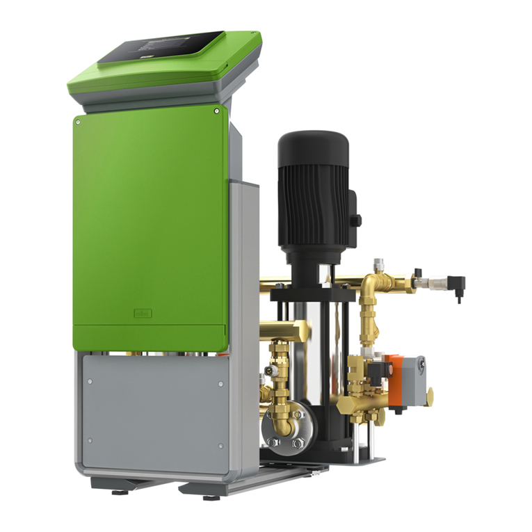
reflex ’variomat’ is a pump-controlled pressure-maintaining, degassing and water make-up station essentially
consisting of a ’variomat’ control unit with pressure sensor, pump, overflow valve, make-up solenoid valve and
safety valve and one or more ’variomat’ vessels.
A diaphragm divides the vessel into a water space and a gas space without a pressurised cushion of air.
The selected technical specification for fulfilment of the fundamental safety requirements outlined in Appendix I
of the directive 97/23/EC can be found on the name plate or in the declaration of conformity.
The declaration of conformity in the appendix certifies compliance with the EU directives 97/23/EC on pressure
equipment and 89/336/EC on electromagnetic compatibility.
Assembly, operation, inspection prior to start-up, periodic inspections
according to the national regulations (in Germany the Betriebssicherheitsverordnung (Ordinance on Industrial
Safety and Health)). In keeping with this, assembly and operation must be performed according to the state of
the art by qualified personnel and specially trained staff. The operator must arrange the necessary inspections
prior to start-up, after substantial modifications to the system and periodic inspections as per the requirements
of the Ordinance on Industrial Safety and Health. Recommended inspection intervals according to § 15 (5) of the
Ordinance on Industrial Safety and Health and classification of the ’variomat’ VG basic vessels and VF secondary
vessels in Table 2 of directive 97/23/EC, see the section “Inspection intervals”. Only VG basic vessels and VF
secondary vessels without visible external damage to the pressure vessel may be installed and operated. Tension-
free (moment-free) installation is required. An additional load from pipelines or devices is not permitted.
Proper assembly and start-up must be certified in the assembly, commissioning and maintenance
certificate (→p. 33). This is a requirement for warranty claims. We recommend having the initial start-up
as well as the annual maintenance performed by your Reflex Service (→p. 31).
Changes to the control unit or the ’variomat’ vessels
such as welding work or adjustments to the circuitry, for instance, are not permitted. If parts are exchanged, only
manufacturer’s original parts may be used.
Adherence to parameters
Details concerning the manufacturer, year of manufacture and serial number as well as the technical data are
provided on the name plate on the ’variomat’ VG basic vessels and ’variomat’ VF secondary vessels. Suitable
safety measures must be implemented to ensure adherence to the permissible maximum and minimum operating
parameters (pressure, temperature, electrotechnical data) specified on p. 29. Violation of the permissible
electrotechnical data and the permissible excess operating overpressure on the water side, both during operation
and when filling, must be ruled out.
Corrosion, incrustation
’variomat’ vessels are made from steel and feature an external coating. Inside, a diaphragm prevents the
expansion water coming into direct contact with the vessel walls. A corrosion allowance of 0.1 mm has been
taken into consideration for the wall thicknesses of the vessels with technical specification AD 2000 (→name
plate). The vessel connections are raw inside. The vessels may only be used in atmospherically closed systems
with non-corrosive and chemically non-aggressive and non-toxic waters. The ingress of atmospheric oxygen
into the entire heating and cooling water system due to permeation, make-up water and so on is to be reliably
minimised during operation. Water treatment systems are to be designed, installed and operated according to
the state of the art.
Thermal protection
In heating water systems, the operator must affix a warning notice near the ’variomat’ system if there is a risk of
injury from excessive surface temperatures.
Installation site
Adequate load-bearing capacity of the installation site must be ensured, taking into consideration the complete
filling of the ’variomat’ VG basic vessels and ’variomat’ VF secondary vessels with water. Installation in earthquake
zones is not permitted. The installation room must be frost-free. A drain is to be provided for the waste water.
Provision is to be made for the addition of cold water if necessary.
Electrical connection
Electrical wiring and connection must be performed by a qualified electrician according to the applicable local
regulations (electricity board, VDE and EN). The system must be de-energised before any work is carried out on
electrical components.
Failure to heed these instructions, in particular the safety instructions, may result in the destruction of and defects
in the ’variomat’, personal injury and impaired operation. Any and all claims for warranty and liability are excluded
if these instructions are violated.
General safety instructions
reflex ’variomat’
General
5

Note:
Please check the delivery for completeness and damage immediately upon receipt of
the goods! Transport damage must be reported immediately!
The scope of delivery is described on the delivery note and the contents
indicated on the cardboard box.
Main components required for proper functioning of the system (→see also p. 3)
’variomat’ control unit on pallet,
connection set connection set in a separate cardboard box, foil pocket
with operating instructions and electrical circuit diagram
VG basic vessel with add-on parts in a foil bag at the vessel foot
Possible options
’variomat’ VF secondary vessel with flexible hose set and add-on parts
in a foil bag at the vessel foot
VW thermal insulation
reflex ’fillset’ (with standard or contact water meter)
Add-on module
Bus modules
Communication module (control panel for remote control)
Choose the installation site. Please note that the control unit and the VG/VF
vessels must be placed one next to the other on the same level.
Requirements for the installation room:
−Frost-free, well-ventilated room; room temperature > 0 to max. 45°C
−No unauthorised access
−Level floor with adequate load-bearing capacity and drainage facility
−Filling connection DN 15, according to DIN 1988 P 4; max. normal
pressure 6.0 bar
−Electrical connection to 230 V~, 50 Hz, 16 A with upstream ground fault circuit
interrupter: tripping current 0.03 A
}
reflex ’variomat’
Assembly
6
Scope of delivery
Installation site

Installation of a
dual-pump system
Installation of a
single-pump system
Connection flange
VG basic vessel up to ∅740 mm
Connection flange
VG basic vessel above
∅1000 mm
Overflow manifold
connection
Pump connection
Hose set
connection for
VF secondary
vessel (optional)
Installation of the VG basic vessel
There are numerous installation variants for the control unit.
– Remove the control unit from the pallet.
– Transport to the installation site, making sure that the control unit is
carried by the frame.
– When aligning the control unit, make sure that the valves and feed
facilities of the connection lines can be operated.
The base plate of the single-pump systems can be turned.
– Align the ’variomat’ control unit and VG basic vessel.
– Tension-free (moment-free) installation is required. An additional load
from pipelines or devices is not permitted.
– The safety valve (27) on the control unit must be equipped with a
blow-out line on site; this line must be laid in such a manner that
any risk of injury from the escaping medium is ruled out.
’variomat’ control unit to the
left of the VG basic vessel
Preferred version
’variomat’ control unit
to the left of the VG basic vessel
Preferred version
’variomat’ control unit
to the right of the VG basic
vessel
’variomat’ control unit
in front of the VG basic
vessel
’variomat’ control unit to the
right of the VG basic vessel
’variomat 2-2’ dual-pump system
’variomat 1 and 2-1’ single-pump system
– Align the VG basic vessel so that the label with the connection faces the
connection points (2x external thread) of the control unit and the distance
to the control unit corresponds to the length of the connection set.
– Assemble the level gauge (→p. 9) and add-on parts (→p. 8).
– Screw the connection set 12using the screw connections to the two
free 1” pipe nipples on the lower vessel flange with seal.
– In the case of dual-pump systems it must be ensured that the longer hose is
used for joining the pump suction side with the vessel.
– Ensure that the overflow manifold connection 1and the pump connection
2are not confused. If they are, there is a risk the pump may run dry.
– It is imperative that the control unit and the VG and VF vessels are
installed at the same level. On no account should the control unit be higher
than the vessels.
WM O P PO WM
WM
O
P
WM
O
P
1
1
1
22
22
22
3
3
3
Label
Label
Water make-up
to the vessel
Overflow from
the system
Pumps to the
system
reflex ’variomat’
Assembly
7
Installation of the ’variomat’ control unit

The hose set 3enclosed with the VF secondary vessel must be assembled
at the outlet of the VG basic vessel intended for this purpose and individually
connected to the piping provided on site.
Only two R1 connection nipples are available on the flange of the VG basic
vessels above 1000 l Ø 1000 mm. In this case the hose set of the VF secondary
vessel has to be assembled at the connection 2using the T-piece.
(Diagram on p. 7.)
Vessel up to ∅740 mm
Vessel above ∅1000 mm
Exploded
view
→see also diagram on p. 7
26
Exploded
view
26
28
Assemble
without cap!
Assemble
without cap!
on site
reflex ’variomat’
Assembly
8
Installation of the VF secondary vessel
Dipstick-tube degassing, venting of the diaphragm compartment
(compensating bend)
The add-on pieces are affixed to the vessel foot and packed in a PE bag.
With VG and VF vessels up to Ø 740 mm:
– Evacuation device with ventilation protection (26)
– Reducing sleeve Rp ½ x Rp ⅜
With VG and VF vessels above Ø 1000 mm:
– Evacuation device with ventilation protection (26)
– Reducing sleeve R 1 x Rp ⅜
These parts must be sealed, assembled and mounted in the middle vessel
connection on the vessel. The plastic cap of the ventilation protection must be
removed.
Assemble the supplied compensating bend (28) with the clamping ring connection
at the vessel connector for evacuation and ventilation of the diaphragm
compartment.
Attention! The compensating bend (28) must not be sealed! A draining facility
must be provided on site, for example via a funnel.
Assembly of the add-on parts for VG
and VF vessels

’variomat 2-2’ with VG basic vessel
and VW thermal insulation
The level gauge should only be mounted when the VG basic vessel is in its final position. The transport protection
(wooden block) at the vessel foot of the basic vessel must be removed and replaced with the pressure cell (23).
Above a vessel size of 1000 l (Ø 1000 mm), the level gauge must be mounted using the screws supplied.
Apply the VW thermal insulation around the VG basic vessel
and close with the zip. We recommend insulating the VG
basic vessel and the expansion lines against the loss of
heat, especially in heating systems. There is no need to
insulate VG secondary vessels.
Since there is an air space between the diaphragm and the
vessel wall, there is no need to insulate the lid.
In the case of possible formation of condensate, we
recommend on-site insulation.
C A U T I O N
The following points must be noted to ensure correct operation of the level gauge:
– The vessel must be freestanding and vertical on a stable and level surface (do not bolt down, set in concrete,
and so on.).
– Auto-zeroing of the filling level may only be performed with the vessel aligned and empty.
– The vessel foot should not be subjected to any impact loads once the level gauge has been mounted (for example
during installation/plumbing of the vessel).
– Always connect the VG basic vessel and the first VF secondary vessel flexibly using the connection sets supplied.
Non-compliance with these instructions may cause measuring errors as well as malfunctions of and damage to the
level gauge.
Level gauge information: VG 200 l : 0 - 4 bar
VG 300 - 500 l : 0 - 10 bar
VG 600 - 1000 l : 0 - 25 bar
VG 1500 - 2000 l : 0 - 60 bar
VG 3000 - 5000 l : 0 - 100 bar
Front view
– Make sure the system is
freestanding!
– Do not tilt the pistons!
– Remove the transport
protection
– Push the oil pressure cell
underneath and bolt onto
the foot in the case of
vessels above 1000 l
(Ø 1000 mm)
Top view
reflex ’variomat’
Assembly
9
Assembly of the level gauge at the
VG basic vessel
Assembly of the level gauge at the
VG basic vessel

The additional degassing function means that two expansion
lines (O, P) must always be installed for the ’variomat’.
Regardless of the ’variomat’ nominal connection width, the
size of the expansion lines must at least correspond to the
values specified in the table.
Integrate the overflow line (O) ahead of the pump line (P)
seen in the direction of flow of the system.
Integrate the ’variomat’ in a representative main flow of
the system.
Max. medium temperature at the integration point 70 °C,
max. glycol content 50%.
To avoid coarse dirt entering and overloading the ’variomat’
dirt trap, integration must be performed according to the
above diagram (see “Close-up of integration point”). Flush
the pipelines of the heating system and the potable water
make-up unit prior to start-up.
In the case of water heating systems according to DIN 12828
(formerly DIN 4751 P2), it must be ensured that only
protected shut-off facilities or none at all are installed
between ’variomat’ and the heat generators. Otherwise the
heat generators must be individually protected
(recommended for ’variomat’).
Individual protection: Owing to the sound degassing
performance of the ’variomat’, it is recommended even
with single boiler systems to install a diaphragm pressure
expansion vessel (for instance ’reflex N’) at the heat
generator to minimise the switching frequency.
Connection line for make-up: If the make-up
line is connected directly to a potable water system, reflex
’fillset’ (shut-offs, system separator, water meter, dirt trap)
must be installed upstream. If reflex ’fillset’ is not installed,
a dirt trap with a mesh size ≤0.25 mm must at least be
installed to protect the make-up solenoid valve. Keep the
line between the dirt trap and the solenoid valve as short as
possible and flush.
If the automatic make-up facility is not connected, the
connection (WM) of the make-up line must be sealed with
a R ½ plug.
Note: If manual make-up is not performed in time, the
’variomat’ pressure-maintaining station will switch to an error.
The normal pressure at the ’variomat’ make-up solenoid
valve must not exceed 6.0 bar. Install a pressure reducer
upstream if required.
- p0= minimum operating pressure, →p. 15
- expansion lines > 10 m length install one
size larger
Connection of the ’variomat’ control unit,
expansion lines
Expansion lines (O, P)
≥500
Main flow V
circuit water
≥500
Main flow V
circuit water
rich in gas low in gas
Main flow V
circuit water
Close-up of integration point
from above
from below as
immersion tube or
from the side
butt-welded
from below -
not permitted
DN DN DN DN
25 32 40 50
variomat 1 x
variomat 2-1/... x
variomat 2-2/35 x
variomat 2-2/... x
p0≤ 3.5 bar
variomat 2-2/... x
p0> 3.5 bar
Water make-up
p ≤6 bar
reflex ’fillset’
max. 70 °C
Control unit VG basic vessel VF secondary vessel
Connection set G 1 reflex ’SU quick
coupling’ R 1x1
Line DN 25 on site
Sizing of
expansion lines
WM O P
Close-up of
integration
point
reflex ’variomat’
Assembly
10

The circuits must be adjusted to suit local conditions.
reflex ’variomat’
Assembly
11
Assembly diagrams
Notes for the installer
reflex ’variomat 1’ in a single-boiler system
≤350 kW, < 100 °C, make-up using potable water
You do not need to install any
additional cap valves in the
expansion line.
reflex ’fillset’ with integrated
system separator must be
installed upstream when
connecting to the potable
water system.
If reflex ’fillset’ is not installed
upstream, a filter for the make-
up unit with a mesh size of
≤0.25 mm must be provided
on site.
Install expansion lines over
10 m in length in DN 32.
→page 12
1)
reflex ’fillset’
’reflex’
’variomat 1’
VG basic
vessel
1)
25
POWM
Potable water
tR≤70 °C
Dirt-free integration
→p. 10
≥500
Boiler and system protection, maintaining
pressure, degassing and water make-up
Water make-up connected directly to
the potable water system
15
reflex ’variomat 1’ in a district heating domestic
station, make-up by means of district heating return Notes for the installer
District heating water is
generally highly suitable
as make-up water. Water
treatment is not required.
The agreement of the heating
supplier is required! Note the
connection conditions.
Install expansion lines over 10 m
in length in DN 32. →page 12
’variomat 2’:
An optional board with 6 digital
input and 6 floating output
contacts and pressure and level
outputs by means of isolation
amplifiers is available for special
requirements, for instance in
connection with district heating.
Please contact us for more
information..
tR≤70 °C, district heating return
tR≤70 °C
Dirt-free integration
→p. 10
’variomat 1’
VG basic
vessel
1)
1)
POWM
Consult the heating supplier concerning the connection
of the make-up unit to the district heating return
Generator and system protection
Maintaining pressure, degassing and make-up
on site
Filter Pressure
reducer
SV
≥500
25 15
’reflex’

The circuits must be adjusted to suit local conditions.
reflex ’variomat’
Assembly
12
Notes for the installer
’variomat’ must always be
integrated in the main flow
in order to be able to degas
a representative partial flow.
In the case of central return
admixture, this is the system
side. The boiler will then be
individually protected.
If the capacity of reflex ’fillset’
is exceeded (kVS = 1 m³/h),
a suitable connection group
must be provided on site as
an alternative in the make-
up line. The filter may have
a maximum mesh size of
0.25 mm.
Sizing of the expansion lines
→Reflex check list for
pressure-maintaining
systems, see page 12
reflex ’variomat 2-1’ in a system with central return
admixture, make-up using softening system
tR≤70 °C
Dirt-free integration
→p. 10
’variomat 2-1’
reflex ’fillset’
VG basic
vessel
1)
POWM Potable
water
Individual boiler
protection
System protection
Maintaining pressure, degassing and make-up
Connection of the water make-up system by
way of a chemical water treatment system
≥500
1)
25 15
’reflex’
reflex ’ET
expansion
trap’
reflex ’fillsoft’
reflex ’variomat 2-2’ in a multi-boiler system,
advance > 100 °C, make-up by way of softening system
tR≤70 °C
Dirt-free
integration →p. 10
’variomat 2-2’
reflex ’fillset’
VG basic
vessel
VF secondary
vessel
1)
Notes for the installer
In the case of water
treatment systems,
reflex ’fillset’ with system
separator and water meter
is installed upstream of the
softening system.
Provide individual protection
with ’reflex’ in the case of
multiple boiler systems.
Several VF secondary
vessels can be
connected.
Sizing of the
expansion lines
→Reflex check list for
pressure-maintaining
systems
Page 12
1)
PO
WM
≥500
System protection
Maintaining pressure, degassing and make-up
Connection of make-up system by
way of a chemical water treatment system
Potable
water
’reflex’
reflex ’ET
expansion
trap’
Piping on site

Electrical wiring and connection must be performed by a qualified electrician according to the applicable local
(electricity board) regulations and VDE regulations. The system must be de-energised before any work
is carried out on electrical components. Comprehensive electrical connection diagrams are enclosed with
these instructions and must be adhered to.
The following information applies only to standard systems and is largely restricted to the connections required
on site.
– Loosen the 2 recessed head screws on the control box (13).
– Open the cover.
– Pass all the cables to be installed through the cable conduit fitting.
Important: Use only cable conduit fittings suitable for the respective cable.
– Connect all cables (refer to the following and electrical circuit diagram).
– Note the connected loads on p. 29 for on-site fuse protection.
Overview of the wiring diagram on the circuit board - ’variomat 2’
J2 7/8 (fourth from
left) occupied
→ Contact water
meter can be
evaluated
reflex ’variomat’
Assembly
13
Designation Terminal Signal Remarks
Supply X0 / 1 L Wiring at the terminal block next to the fuses, pre-wired
with a shock-proof plug
(230 V) X0 / 2 N
X0 / 3 PE
Supply X0 / 1 L1
Wiring at the terminal block next to the contactors -
wire ’variomat 2’ on site
(400 V) X0 / 2 L2
X0 / 3 L3
X0 / 4 N
X0 / 5 PE
Make-up (4) 4 Y1
Wire on site, optional(230 V) 5 N
6PE
Dry-running
protection message
13
Wire on site, optional14
(floating)
Common message 23 NC
(floating) 24 COM Wire on site, optional
25 NO
Level gauge 35 +18 V
Is connected in the control box, put the plug on the
pressure cell on site and screw on tightly
(pressure cell) 36 GND
(8) 37 AE
38 PE (screen)
Contact water meter
(optional)
43 +24 V DC Wire on site, additionally connect the pins 7/8 on the
jumper block J2 (see above figure)
44 E1
Pressure
transducer (4)
39 +18 V
Is connected
40 GND
41 AE
42 PE (screen)
Pump 1 (2) 15 M1
(230 V) 16 N Is connected
17 PE
Electrical connection
I/O circuit board - single-pump system I/O circuit board - dual-pump system

Designation Terminal Contactor
terminal Signal Remarks
Pump 2 18 M2
(230 V) 19 N Is connected
20 PE
Pump 1 (2) 6K1 / 2 U
(400 V) 6K1 / 4 V
6K1 / 6 W
X0 / 6 PE
Pump 2 6K5 / 2 U
(400 V) 6K5 / 4 V
6K5 / 6 W
X0 / 7 PE
Overflow solenoid
valve 1 (5)
7Y2
8N
Is connected
9PE
Overflow solenoid
valve 2
10 Y3
Is connected11 N
12 PE
Motorised ball
valve 1
55 GND
56 +24 V Supply
57 0 - 10 V Manipulated variable
58 0 - 10 V Feedback
Motorised ball
valve 2
51 GND
52 +24 V Supply
53 0 - 10 V Manipulated variable
54 0 - 10 V Feedback
RS-485 The interface is positioned at the display board in the bottom
interface left corner of the control box door. Description → p. 24
reflex ’variomat’
Assembly
14
Designation Terminal Signal Remarks
Supply 1 PE
’variomat 1’ line wired with a shock-proof plug(230 V) 2 N
3L
Make-up (4) 10 Y1
(230 V) 11 N
12 PE
Common message 13 COM
(floating) 14 NC
15 NO
Level gauge 19 PE Screen
(pressure cell) 20 - level Signal
(8) 21 + level + 18 V
Pressure
transducer (4)
22 PE Screen
23 - pressure Signal
24 + pressure + 18 V
Pump 1 (2) 4 PE
(230 V) 5 N
6M1
Overflow solenoid
valve 1 (5)
7Y2
8N Is connected
9PE
Overview of the wiring diagram on the circuit board - ’variomat 1’

The following information need only be noted in the case of special settings and problems with the
soft start.
All ’variomat 2’ pressure-maintaining systems are fitted with a soft start and stop facility for the pump as
standard. The starting and stopping times and the motor start moments can be set using the potentiometers
(1-6) on the circuit board in the control box. By default, the starting (tup) and stopping (tdown) times are set to
approx. 3 seconds. You should not change these settings. The default settings of the potentiometers are
indicated by a dot. The operating power for the pump is only passed through the soft start during the starting or
stopping times. After that, the power is switched over to the main relay. This is indicated by the LEDs 7 and 8.
The soft start for the ’variomat 1 and 2-1’ is only equipped for one pump (motor 1).
If the soft start board is defective it can be removed and the motors can be switched directly using the relay on
the I/O base board. Two additional jumpers must be present for this to be possible. If the “contact water meter”
function is not used, the corresponding jumpers on terminal strip J2 can be used.
Caution: If the soft start fails, the pump must be checked for stiffness, blocking, or other failures.
– For ’variomat 2-1’ remove three cables and for ’variomat 2-2’ five cables with flat plugs leading to the soft
start from the I/O base board.
– Remove the 10-pin plug of the flat cable.
– Release the two fastening clips that lock the cover of the soft start board into place and remove the
cover plate.
– Unscrew the four M4 plastic nuts and remove the soft start board. The plastic spacers can remain on the
base board.
– On the I/O base board, 2 jumpers must be placed on the pin strip X4 SOFT-START at the positions 1-2
and 3-4.
– Close the control box door once all the connections have been established.
– Tighten the 2 screws on the control box door.
– Establish the power supply.
– The system version appears in the display of the controller.
The ’variomat’ controller is now
ready for initial start-up.
I/O circuit board
Cover plate of the soft start board
12 3 7 8 456
reflex ’variomat’
Initial start-up
15
Soft start
Designation Terminal Signal Remarks
Motorised ball
valve 1
25 0 - 10 V Manipulated variable
26 0 - 10 V Feedback
27 GND
28 +24 V Supply
RS-485 In the case of ’variomat 1’, the interface is provided for updating the program only.
interface
With ’variomat 1’, the external fuse must not exceed A.

reflex ’variomat’
Initial start-up
16
The start routine commences when the controller is switched on for the first time. Its
purpose is to set the parameters required for operation of the ’variomat’ unit. If you enter
an incorrect value, you can restart the routine by pressing the “quit” button.
Caution: The start routine can only be run through once; any subsequent parameter
modifications have to be performed in the customer menu (→p. 21).
The start routine of the ’variomat’ is automatically
called up when the controller is switched on for the
first time.
Press “ok” to get to the language selection:
Select the language using the country code, for
instance “GB” for the English language, and confirm
with “ok”.
A message to read these operating instructions
appears. Confirm with “ok”.
Set the minimum operating pressure p0 according
to the static height of your system (refer also to the
diagram below) and confirm with “ok”.
We recommend that you have the following steps and training of the operating personnel carried out by your Reflex
Service (→p. 31, chargeable service according to the applicable gross price list).
– The VG and VF vessels have been installed and the ’variomat’ control unit assembled.
– The water connection to the system has been established.
– The connection system must be at least roughly bled.
– The vessel(s) must not be filled with water.
– The system has been connected to the electrical mains system according to the applicable VDE and local electricity
board regulations.
variomat
Country: GB
D GB F NL PL
Read operating
instructions!
Min.oper.press.
P0 = 1.5 bar
ok
ok
ok
ok
*Error message if pressure
is exceeded or fallen
below; with ’variomat 2’,
the mechanical overflow
valve also closes if p0is
fallen below
The value set for the minimum
operating pressure p0may not
drop below 1.3 bar, hydraulic
balancing is otherwise
not guaranteed and stable
degassing operation is not
possible.
p0≥1.3 bar
pSV
p0
H, pst
Prerequisites for start-up
Start routine
*
pSV [bar] = Safety valve response pressure at the heat generator
pmax [bar]
≥ 0.5 bar
pe[bar] = Final pressure = overflow device OPEN 0.3 bar
pa[bar] = Initial pressure pump ON 0.4 bar
p0[bar] = pstatic + pevaporation + 0.2 bar (recommended) ≥ 0.3 bar
0...0.2 bar
pst [bar] = Static pressure (= static height / 10) *

Start by setting the current hour (in this case: 18) with the
arrow buttons and confirm with “ok”. Continue with the minutes
(in this case: 46) and the seconds (in this case: 29).
Start by setting the current day (in this case: 29) with the arrow
buttons and confirm with “ok”. Continue with the month (in this
case: 11) and the year (in this case: 01).
A check is performed as to whether the signal issued by
the level gauge (oil cell) at the foot of the VG basic vessel
corresponds to the factory-set vessel in the controller.
Proper assembly of the ’variomat’ system according to these
instructions is absolutely necessary for correct balancing
(→see also p. 9).
The vessel type can be balanced here (see name plate on
the VG basic vessel).
If auto-zeroing has been successfully performed, this
is indicated as scrolling text. The message “Auto-zero
successfully executed!” is displayed. In this case, the
following 2 paragraphs are skipped.
If the controller detects a value that is not plausible, the
message “Empty container + repeat balancing!” is
displayed.
If auto-zeroing cannot be performed despite verification of
the above points, it can be cancelled. To do so, confirm the
message “Empty container + repeat balancing!” using “ok”.
The question “Abort auto-zero? Yes/No” is displayed. Select
your answer using the arrow keys. If you choose “Yes”, the
correct vessel must be selected in the service menu after the
start routine is completed (please notify Reflex Service).
At the end of the start routine you will be asked whether you
wish to exit the start routine. If you choose “Yes” and confirm
with “ok”, the system automatically switches to stop mode. It
should be left in stop mode in order to undertake additional
start-up measures.
If you choose “No”, the start routine is repeated.
You are now in stop mode.
Important: Do not switch to
automatic mode yet.
Time:
18:46:29
Date:
29.11.01
2% 2.1 bar
Auto-zero
0% 2.1 bar
Auto-zero successfully
0% 2.1 bar
Empty vessel +
Abort
auto-zero? No
Exit
routine? Yes
0% 2.1 bar
Stop
ok
ok
ok
ok
ok
ok
ok
Important: The VG
basic vessel must be
empty.
reflex ’variomat’
Initial start-up
17
00800 l 740 mm
Weight = 0149 kg

reflex ’variomat’
Initial start-up
18
Example:
Bleed screws
’variomat 2-2/60’
The following information applies to all ’variomat’ systems with VG basic vessel and/or
one or more VF secondary vessels (expansion vessels).
Important: The VG and VF vessels must be empty for setting of the ’variomat’
controller. Auto-zeroing of the level gauge must therefore be performed before
the vessels are filled (see start routine/customer menu).
Filling with a hose using the filling and draining tap (17) on the vessel.
This variant is recommended and useful if the automatic water make-up facility of the
’variomat’ has not yet been connected on the water side.
To do this, connect a water hose from the water supply to the filling and draining tap
(17) on the vessel. Open the protected shut-offs between the control unit and the vessel
(factory setting: open).
Prerequisite: The VG basic vessel of the ’variomat’ is filled (see abovementioned
point) and protected ball valves (21) are open (factory setting: open).
Loosen the bleed screw (9) of the pressure-maintaining pump and bleed the pump
until water containing no bubbles runs out. Tighten the bleed screw again and check
for watertightness. For ’variomat 2-2’, repeat procedure for second pump.
It may be necessary to repeat this process several times if the delivery performance
of the pump/pumps remains poor.
Caution must be exercised at high temperatures!
Note the general safety instructions!
stop
hand
Switch on the controller (→p. 16) and set it to “Stop”
operating mode. (This is used to show the water level in the
vessel.) The display should now be showing “0%”.
Open the filling and draining tap (24) and fill the vessel:
– Heating system approx. 30%
– Cooling and air conditioning system approx. 50%
0% 2.1 bar
Stop
30% 2.,1 bar
Stop
24
12
Filling with the water make-up solenoid valve
Open the water make-up solenoid valve in manual mode and fill the vessel (→p. 20).
1.
2.
Filling the vessels and control unit
Bleeding the pumps

You can change to automatic mode once the settings have been made and the entire
system filled and bled. The ’variomat’ will now be in the continuous degassing program
for 12 h (this time can be set in the customer menu) and will then automatically switch to
the “follow-up degassing” program.
The ’variomat’ is now in operation.
The initial start-up services to be provided by Reflex Service are now complete.
Important: Please note the general safety instructions.
The dirt traps must be cleaned after expiry of the continuous degassing time
at the latest.
Set the system to stop mode.
– Close the ball valve (6) on the ’variomat’.
– Twist off the cap on the dirt trap (4) (open slowly to reduce the excess pressure in the
pipeline). Remove together with the dirt trap insert.
– Remove the strainer from the cap and rinse under clean water. Brush with a soft brush.
– Replace the strainer in the cap, check the seal for damage and screw back into the dirt
trap housing.
– Open the ball valve.
– Bleed the pump (10) by means of the bleed screw (12).
– Close the bleed screw (12).
auto
stop
30% 2.1 bar
Stop
Initial start-up is now complete!
Dirt trap insert
reflex ’variomat’
Initial start-up
19
Automatic mode
Cleaning the dirt traps
Dirt trap (4)

General
Automatic mode may only be started after initial start-up has been successfully
completed. The function to maintain pressure, compensate the expansion volume, degas
and automatically make-up water is then active.
The pump and overflow motorised ball valve are actuated so that the pressure remains
constant within the limits ± 0.2 bar. The electronic controller monitors the functions. Faults
are displayed and evaluated. If the default setting is not changed, after initial start-up
the ’variomat’ will operate in the “continuous degassing” program for the time set in the
customer menu.
Degassing program variants
Continuous degassing
Intensive degassing following start-up and repairs to the connected pipe network. The
degassing cycles are executed successively for the set continuous degassing time
(12 h basic setting). The controller then automatically proceeds with follow-up degassing.
Interval degassing – Economy mode in automatic mode
Is executed according to a defined schedule. Degassing takes place at defined intervals
for a defined time. The necessary specifications can be made in the service menu. The
option is also provided of allowing interval degassing within a specific time window only.
(Service menu.)
Follow-up degassing
Takes place automatically each time the pump starts. (The corresponding overflow
motorised ball valve opens following the switch-off signal for the pump.) The pump and
the valve keep working simultaneously for a time defined in the service menu.
The selected degassing program is shown in the message line during execution of
the respective program only.
In manual mode all pumps or solenoid valves can be turned on or off. To activate manual
mode, press the “hand” operating mode button. The adjacent display appears. All pumps
or solenoid valves in operation will be switched off.
Example: Turning on and off pump 1
Select P1 (flashes) Pump 1 on (P1! flashes)
Pump 1 off
Several devices can be turned on at once. Devices that are turned on are indicated by
an exclamation mark.
The function of the pumps and overflow valves is monitored for safety-relevant
parameters. If several devices are turned on, they are turned off in reverse order by
repeatedly pressing the “quit” button. Once all devices are turned off, you are in stop
mode.
Example:
Pump 1 and overflow valve 1
are turned on.
P1 is selected and can be
switched by pressing the
“ok” button.
Only the display of the ’variomat’ is operational in stop mode. Operation monitoring does
not take place. All pumps, motorised ball valves or solenoid valves are switched off. The
adjacent display appears when the “stop” button is pressed.
A message will be output if stop mode is active for more than 4 hours.
auto
hand
stop
30% 2.1 bar
Interval deg.
30% 2.1 bar
Follow-up deg.
30% 2.1 bar
Continuous deg.
30% 2.1 bar
P1! P2 O1! O2 WM
25% 1.8 bar
Stop > 4 h 19
25% 1.8 bar
Stop
ok
quit
reflex ’variomat’
Operation
20
Automatic mode
Manual mode
Stop mode
This manual suits for next models
7
Table of contents
Other Reflex Control System manuals
Popular Control System manuals by other brands

EUCHNER
EUCHNER CE Series operating instructions

Lennox
Lennox Icon Hardware Installation and System Commissioning Guide

Next Wave Automation
Next Wave Automation CNC Shark HD4 owner's manual

Beijing StarFire Control Technology Co., Ltd.
Beijing StarFire Control Technology Co., Ltd. SF-2012AH-QG user manual

Leica Geosystems
Leica Geosystems iCON grade iGG Series installation manual

A2T
A2T NT-120S operating manual