IDEC HR1S-AF 5130B/PB User manual

HR1S-AF 5130B / PB SAFETY RELAY MODULE OPERATING INSTRUCTIONSHR1S-AF 5130B / PB SAFETY RELAY MODULE OPERATING INSTRUCTIONS
S1A41657.01 B-492(7) 5/2010
1 / 16
非常停止回路モニタ用安全リレーモジュール
(EN/IEC60204-1 / ENISO/ISO13849 / ENISO/ISO
13850適合)
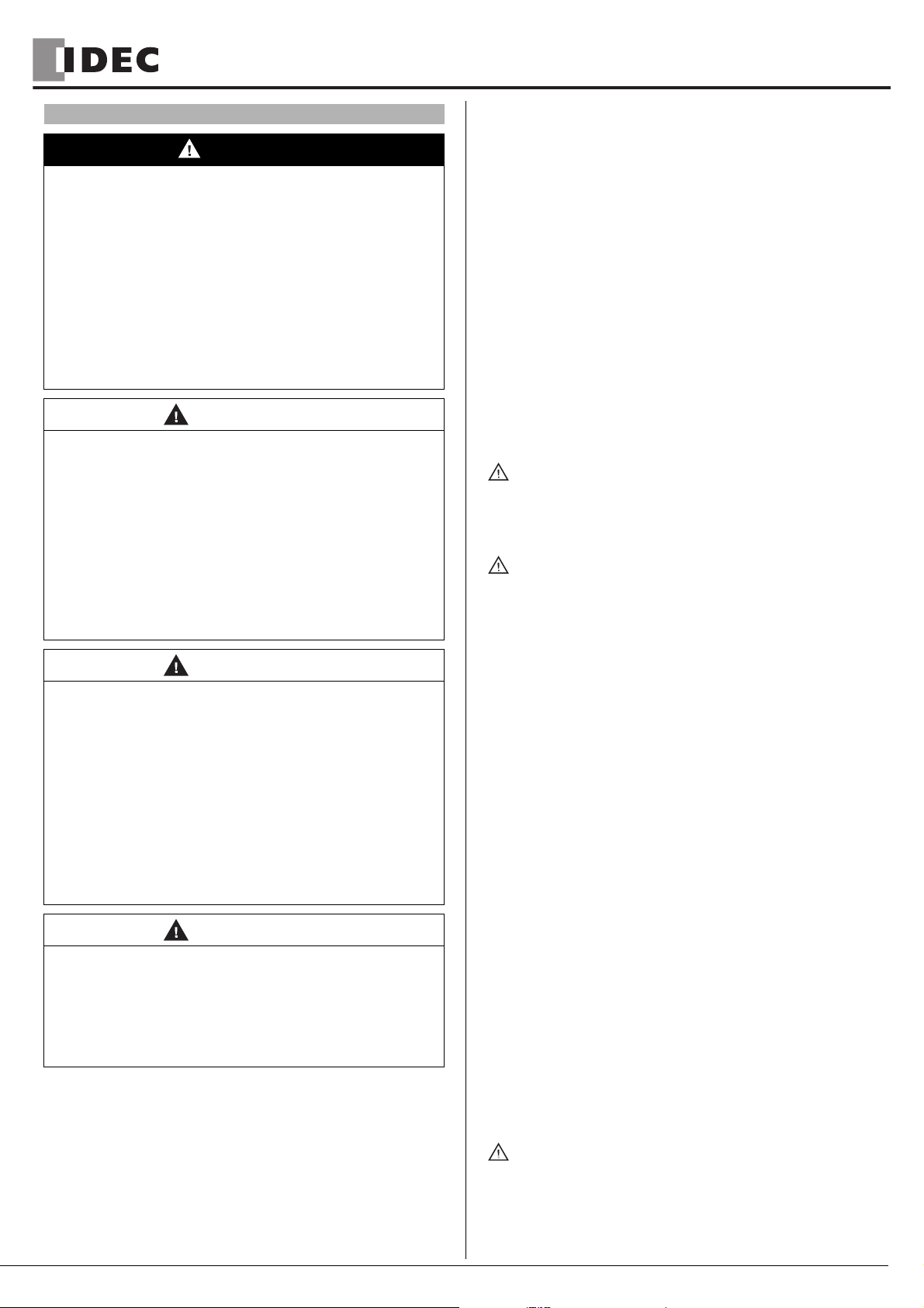
外形寸法
端子配列
正面図
A1/A2 − Fuse LED 緑
K1 LED 緑
K2 LED 緑
22.5 mm
(0.89 in)
114 mm
(4.48 in)
99 mm
(3.89 in)
HR1S-AF5130B
22.5 mm
(0.89 in)
114 mm
(4.48 in)
99 mm
(3.89 in)
HR1S-AF5130PB
HR1S-AF5130PB
HR1S-AF5130B
HR1S-AF5130PB
危険
危険電圧に関する遵守事項
本モジュールの取り付け、起動、構成の変更、部品の追加は、必ず訓練を受け
た専門の電気技術者が行ってください。
作業を開始する前に、モジュールやシステムの電源をすべて切断してください。
取り付けたモジュールまたはシステムでエラーが発生した場合は、DCアイソ
レーションが行われずに、モジュールの制御回路に線間電圧がかかっている可
能性があります。
関係する専門機関や事業者団体が公布する電気関連のすべての安全規制を遵守
してください。本来の用途以外でモジュールを使用された場合、安全機能が失
われる可能性があります。
筐体を開いたり、その他の不正な操作を行った場合、保証は無効になります。
上記の指示を厳守できない場合、死亡事故や重傷を伴う事故につながる恐れが
あります。
注意
用途外使用
モジュールが不適切または誤って使用されている場合は、使用を中止してくだ
さい。この場合、保証は無効となります。
落下や規格外の電圧、電流、温度、湿度など、強い機械的ストレスを与えた状
態で使用しないでください。
初回起動時は、規定に従って事前に機械や設備の安全機能をすべて確認し、安
全装置についても、規定の周期に沿ってテストを行ってください。
上記の指示を厳守できない場合、怪我を伴う事故やモジュールの損傷につなが
る恐れがあります。
注意
取り付け時のリスク
取り付け、組み立て、分解時は、事前に以下の予防措置を行ってください。
1. 作業を開始する前に、モジュールやシステムの電源電圧を遮断する。
2. モジュールやシステムのロックアウトやタグ付けを行って、不慮の起動を防
止する。
3. 電圧が印加されていないことを確認する。
4. 配線図に記載の N(-) を接地する。
5. 保護装置や防壁を使用して近接した動作中の部品から保護する。
6. モジュールは、保護構造が IP54以上のエンクロージャ内に設置する。
上記の指示を厳守できない場合、怪我を伴う事故やモジュールの損傷につなが
る恐れがあります。
注意
接点保護の制限
・ 保護構造は EN/IEC60529に従ってください。
・ 筐体 / 端子部 :IP40/IP20
・ フィンガープロテクションは EN50274に従ってください。
上記の指示を厳守できない場合、怪我を伴う事故やモジュールの損傷につなが
る恐れがあります。
A1
13
S33
23
S34
24
S39
33
14
A2
S21
S11
S22
S12
34
HR1S-AF5130B HR1S-AF5130PB

HR1S-AF 5130B / PB SAFETY RELAY MODULE OPERATING INSTRUCTIONSHR1S-AF 5130B / PB SAFETY RELAY MODULE OPERATING INSTRUCTIONS
2 / 16
用途
安全システムは多数の部品から成り立つものであり、一つの安全部品のみでシステ
ムの安全性を保証するものではありません。最初に、どのような安全システムを構
築するのかを考え、安全システムを構成する部品の取付、配線時は適用安全規格に
従うことが必要です。
HR1S-AF モジュールは、単独または複数の回路を遮断することができ、以下の用
途を想定して設計されています。
・ 手動起動または自動起動
・ 3個の安全出力、1個の補助出力
・ フィードバックループで外部コンタクタをモニタリング
非常停止回路モニタ用安全リレーモジュール
・ EN/IEC 60204-1・EN ISO/ISO 13850 適合の非常停止モニタ用安全リ
レーモジュール
・ 停止カテゴリ 0(EN/IEC60204-1)
- PLe/ カテゴリ 4
- MTTFd=243年
- DC99% 以上
- PFHd=4.62x10⁻⁹
-SILCL3
・ 安全ガードのリミットスイッチのモニタリング
・ 入力を 2 チャンネルで使用すると、入力回路のモニタや配線ミスを含む初期故
障等を検出することが可能。
(配線について)
HR1S-AF 安全リレーモジュール配線図を参照してください。
(短絡保護ヒューズについて)
HR1S-AF には内部に電子ヒューズが組込まれており、外部短絡(入力回路のプラ
ス側とマイナス側間の短絡等)による破損から機器を保護します。なお、故障要因
が取り除かれると、2 〜 3 秒で再び操作可能になります。
外部接続するヒューズはHR1S-AF安全リレーモジュール配線図に従って接続して
下さい。また、ヒューズは巻末の仕様を参照して選定下さい。
適切な使用
本モジュールは、各機械の安全装置で使用される非常停止ボタンやポジションス
イッチなどのセンサをモニタリングし、作業者や構成部品、機械類を保護します。
注記
・ ENISO/ISO13849-1適合のパフォーマンスレベルや安全カテゴリは、外部
配線、用途、使用する制御機器とその機械上での物理的な配置により変化します。
・ ENISO/ISO14121-1に従ってリスクアセスメントを行ってください。
・ 本書に基づき、適合規格に従ってシステムと機械を総検証してください。
・ モジュールには電気機械リレーが内蔵されています。このため、表示されるパ
フォーマンスレベル(PL)値や MTTFd値は、使用時の負荷や動作回数に応じ
て変化します。上述の PL値および MTTFd値は、定格負荷で年あたりの開閉回
数が最大 6,336 回、または低負荷で開閉回数が最大 316,800 回に相応します。
・ 電流負荷がわかっている場合は、電気的寿命のグラフ(5/16ページを参照)を
使用して最大開閉回数を算出してください。この方法で算出した開閉回数での
み、指定したパフォーマンスレベルを確保することができます。モジュールは、
寿命を超えて使用されることのないよう、算出した最大値に到達したら交換して
ください。
・ 仕様に記載のないモジュール操作を行った場合、誤動作やモジュールの破損が生
じる可能性があります。
・ 入力 A1は制御入力として機能します。これにより、短絡を遮断したり、動作電
圧U
Bより低くして放出経路に切り替えることができます。
・ ポジティブな機械的作用を持つ拡張機器または外部コンタクタを使用して、安全
出力を 2重化できます。
・ 起動スイッチを使用する時は、非常停止回路は閉じている必要があります。
・ リード接点付磁気スイッチまたは半導体出力付センサを使用している場合は、ス
イッチがオンのときの最大電流に注意が必要です(「仕様」を参照)。
・ 取り付けに関する注記をご覧ください。
注記
安全関連機関の指示を遵守してください。
注記
・ 絶対に分解しないで下さい(封印シールを破損しないようご注意下さい)。
・ ENISO/ISO13850・EN/IEC60204-1 準拠の安全回路を構成する安全機
器には、13-14 間、23-24 間、33-34 間の出力を使用して下さい。
注意
残留リスク(ENISO/ISO12100-1)
以下の配線図は、実際の使用条件下で慎重にテストしたものです。適用規格に
準拠した安全装置と接続することにより、モジュールは安全機能を発揮できま
す。しかし、次のような場合には、残留リスクを考慮してください。
a) 推奨された回路構成を変更する必要があり、追加・変更された部品が制御回
路に正しく組み込まれていない場合。
b) 機械操作の適用規格に従わなかった場合。または、機械の調整・保守が適切
でない場合。規定された機械保守スケジュールを厳守してください。
c) 安全出力に接続された機器の接点が強制ガイド式でない場合。
上記の指示を厳守できない場合、怪我を伴う事故やモジュールの損傷につなが
る恐れがあります。
警告
回路構成と保守に関する遵守事項
・ 配線例に従い安全リレーモジュールを配線すること。
・ 適合規格に従い配線すること。
・ 安全出力に接続するリレーやコンタクタの接点が強制ガイド式(EN50205
適合)であること。
・ 機械を保守・調整するときは規定された保守スケジュールを厳守すること。
上記の指示を厳守できない場合、死亡事故や重症を伴う事故、またはモジュー
ルの損傷につながる恐れがあります。
危険
取付/取り外し、配線作業及び保守/点検は、必ず電源を切って行って下さい。
感電により、死亡事故や重傷を伴う事故につながる恐れがあります。

HR1S-AF 5130B / PB SAFETY RELAY MODULE OPERATING INSTRUCTIONSHR1S-AF 5130B / PB SAFETY RELAY MODULE OPERATING INSTRUCTIONS
3 / 16
HR1S-AF 安全リレーモジュール配線図
S1
HR1S-AF
TK1
K2
K3
K4
K3
K4
K3
K4
K3 K4
L(+)
N(–)
LOGIC
S2
K4
K3
ESC (1) (2)
F1
(3)
13 23 33S39S34S33A1
14 24 34S22S21S12S11A2
F2
(3)
F3
(3)
24V
(3) 出力用保護ヒューズに関しては
仕様(5/16)を参照ください。
非常停止
スイッチ
S2 の故障
モニタを
行う場合
起動
スイッチ
安全出力 3 回路
S2 の故障
モニタを
行わない場合
ESC =外部起動条件
非常停止
スイッチ
14 24 34A2 S11 S12 S22S21
S1 11
12
21
22
非常停止
スイッチ
A1
A2 S11 S12 S22S21
S1 11
12
非常停止スイッチ1
非常停止スイッチ2
非常停止スイッチ3
14 24 34A2 S11 S12 S22S21
S1 11
12
21
22
S2 11
12
21
22
S3 11
12
21
22
入力 1 チャンネルで使用する場合(カテゴリ 1)
(注:非常停止スイッチ配線の短絡等、全ての故障は
検出できません)
入力 2 チャンネル/短絡検出を行う場合(カテゴリ 4)(推奨) 多数の非常停止スイッチを使用する場合(カテゴリ 3)
A1 S33 S39 13 23 33S34
起動スイッチを使用しない場合(自動スタート)
起動スイッチ
A1 S33 S39 13 23 33S34
S2 13
14
起動スイッチのモニタ
(起動スイッチのオフチェック)を行う場合
起動スイッチ
A1 S33 S39 13 23 33S34
S2 13
14
起動スイッチのモニタを行わない場合
(注:起動スイッチの接点溶着等は検出できません)
入力A
安全ガード開
S1 S2
入力B
A2 S11
34 12
S12 S22S21
リミットスイッチまたは安全スイッチを使用する場合/
短絡検出を行う場合(カテゴリ 4)
(下図は安全ガード閉状態を示す)

HR1S-AF 5130B / PB SAFETY RELAY MODULE OPERATING INSTRUCTIONSHR1S-AF 5130B / PB SAFETY RELAY MODULE OPERATING INSTRUCTIONS
4 / 16
HR1S-AF 安全リレーモジュール動作チャート図
LED 表示
① A1/A2-Fuse : 電源回路が正常な時に点灯
電源が遮断されたり、電子ヒューズが機能した時に消灯
② K1 : K1 リレー動作時に点灯
③ K2 : K2 リレー動作時に点灯
電源ON 起動スイッチ操作 非常停止操作
動作表示 閉開
非常停止スイッチ
S11-S12(NC1)
非常停止スイッチ
S21-S22(NC2)
起動スイッチ
S33-S34(NO)
起動スイッチ
S33-S39(NO)
出力13-14(NO)
出力23-24(NO)
出力33-34(NO)
①
②
①
②
起動スイッチのモニタ
(起動スイッチのオフチェック)
を行う場合
起動スイッチのモニタ
を行わない場合
(起動スイッチの接点溶着等は
検出不可能)
非常停止スイッチを使用したアプリケーション
電源ON スイッチ
S1操作
スイッチ
S2操作
安全ガード開
安全ガード開
t=∞
安全ガード閉
動作表示 閉開
入力A(S11-S12)
入力B(S21-S22)
S33-39短絡
出力13-14(NO)
出力23-24(NO)
出力33-34(NO)
安全ガードを使用、自動スタートのアプリケーション

HR1S-AF 5130B / PB SAFETY RELAY MODULE OPERATING INSTRUCTIONSHR1S-AF 5130B / PB SAFETY RELAY MODULE OPERATING INSTRUCTIONS
5 / 16
出力接点の電気的寿命(EN/IEC60947-5-1/付録 C.3 による)
仕様
- 製造年 2010 年
- 端子と接続
HR1S-AF5130B
単線接続
ケーブル終端なし
単線: 0.14 〜 2.5mm2
より線: 0.14 〜 2.5mm2(26 〜 14AWG)
ストリップ長さ: 7mm(0.28in.)
ケーブル終端つきフレキシブル
(ビニール被覆なし): 0.25 〜 2.5mm2(24 〜 14AWG1))
(ビニール被覆あり): 0.25 〜 1.5mm2(24 〜 16AWG1))
最小締付けトルク : 0.5Nm(4.4lb-in)
複線接続(最大 2 本)
ケーブル終端なし
単線: 0.14 〜 0.75mm2(26 〜 20AWG1))
より線: 0.14 〜 0.75mm2(26 〜 20AWG1))
ストリップ長さ: 7mm(0.28in.)
ケーブル終端つきフレキシブル
(ビニール被覆なし): 0.25 〜 1mm2(24 〜 18AWG1))
ツインケーブル終端つきフレキシブル
(ビニール被覆あり): 0.5 〜 1.5mm2(22 〜 14AWG1))
最小締付けトルク : 0.5Nm(4.4lb-in)
HR1S-AF5130PB
単線接続
ケーブル終端なし
単線: 0.2 〜 2.5mm2
より線: 0.2 〜 2.5mm2(24 〜 12AWG)
ストリップ長さ: 7mm(0.28in.)
ケーブル終端つきフレキシブル
(ビニール被覆なし): 0.25 〜 2.5mm2(22 〜 14AWG1))
(ビニール被覆あり): 0.25 〜 1.5mm2(22 〜 16AWG1))
最小締付けトルク : 0.5Nm(4.4lb-in)
複線接続(最大 2 本)
ケーブル終端なし
単線: 0.2 〜 1mm2(24 〜 18AWG1))
より線: 0.2 〜 1.5mm2(24 〜 16AWG1))
ストリップ長さ: 7mm(0.28in.)
ケーブル終端つきフレキシブル
(ビニール被覆なし): 0.25〜1mm2(22 〜 18AWG1))
ツインケーブル終端つきフレキシブル
(ビニール被覆あり): 0.5 〜 1.5mm2(20 〜 16AWG1))
最小締付けトルク : 0.5Nm(4.4lb-in)
1)AWG指標は EN/IEC60947-1/表 1に準拠
- 取り付け: 35mmDIN レール(EN/IEC60715)
- 保護構造(EN/IEC60529)
端子部: IP20
筺体: IP40
- 重量: 0.25kg
- 取り付け方向: 全方向
- 使用周囲温度: -25 ℃〜 +55 ℃
- 過電圧カテゴリⅢ(4kV)
汚染度 2
定格絶縁電圧: AC300V
(EN/IEC60664-1)
- 電源電圧 UE(IEC60038)
AC/DC24V: (+10%/-15%)
最大保護:4A ヒューズ(タイプ gL)
- 消費電力
AC/DC24V: ≦ 5VA
- 安全リレー出力:
13-14 間、23-24 間、33-34 間
- 出力接点定格:
AC15 :Ue = AC240V/le = 0.75A
DC13 :Ue = DC24V/le = 1.5A
- 機械的寿命(開閉操作) :10x106
- 全出力の通電電流合計 :ΣIth ≦18A
- 出力用保護ヒューズ :4Aヒューズ(gL)または即断形 6A ヒューズ
- 応答速度 :S11-S12、S21-S22 遮断時≦20ms
A1,A2(電源ライン)遮断時≦60ms
- 入力 A と入力 B が同期しなければならない時間
(起動スイッチを使用せず、自動スタートさせる場合):t=∞
- 出力の最小適用負荷:17V/10mA(初期状態)
- 入力間の許容最大抵抗:90Ω
形式
使用電流x0.1A
動作回数
100
10
104105106107
1
AC15:230V
DC13:24V
DC1:24V
AC1:230V
形式 定格電源電圧
HR1S-AF5130B 24VAC/DC 端子一体型
HR1S-AF5130PB 24VAC/DC 端子分離型

HR1S-AF 5130B / PB SAFETY RELAY MODULE OPERATING INSTRUCTIONSHR1S-AF 5130B / PB SAFETY RELAY MODULE OPERATING INSTRUCTIONS
S1A41657.01 B-492(7) 5/2010
6 / 16
Module de surveillance pour circuits d’ARRET D’URGENCE
selon EN / IEC 60204-1, EN ISO / ISO 13849,
EN ISO / ISO 13850
(Traduction de l’instruction de service originale)
Safety Relay for monitoring EMERGENCY STOP circuits
according to EN / IEC 60204-1, EN ISO / ISO 13849,
EN ISO / ISO 13850
(Original instruction sheet)
Überwachungsbaustein für Not-Halt Kreise
gemäß EN / IEC 60204-1, EN ISO / ISO 13849,
EN ISO / ISO 13850
(Übersetzung der Originalbetriebsanleitung)
Encombrements / Dimensions / Maße
Repérage des bornes / Terminal marking / Klemmenanzeiger
Vue de face / Front View / Frontansicht
A1/A2 - Fuse LED verte / green / grün
K1 LED verte / green / grün
K2 LED verte / green / grün
FR EN DE
22,5 mm
(0.89 in)
114 mm
(4.48 in)
99 mm
(3.89 in)
HR1S-AF5130B
22,5 mm
(0.89 in)
114 mm
(4.48 in)
99 mm
(3.89 in)
HR1S-AF5130PB
HR1S-AF5130PB
HR1S-AF5130B
HR1S-AF5130PB
A1
13
S33
23
S34
24
S39
33
14
A2
S21
S11
S22
S12
34
HR1S-AF5130B HR1S-AF5130PB
HR1S-AF 5130B / PB SAFETY RELAY MODULE OPERATING INSTRUCTIONSHR1S-AF 5130B / PB SAFETY RELAY MODULE OPERATING INSTRUCTIONS
7 / 16
Application
Le module HR1S-AF sert à interrompre en toute sécurité un ou plusieurs
circuits, et est conçu pour les applications suivantes:
• Démarrage manuel ou automatique
• 3 contacts de sortie, 1 contact de signalisation
• Boucle de rétroaction pour le contrôle de contacteurs-disjoncteurs
externes
Module de surveillance pour circuits d’ARRET D’URGENCE
• Module de surveillance conformément à EN / IEC 60204-1, EN ISO /
ISO 13850 pour le contrôle de l’arrêt d’urgence.
• Pour catégorie d’arrêt 0 selon EN/IEC 60204-1:
- PL e / Catégorie 4
-MTTF
d= 243 Années
- DC = 99%
-PFH
d= 4,62 x 10⁻⁹ 1/h
- SILCL 3
• Surveillance des interrupteurs de position actionnés par des dispositifs
de protection.
Le module est conçu pour l’utilisation d’entrée à une ou deux voies. Nous
préconisons l’utilisation de deux voies d’entrée qui augmente ainsi le
niveau de sécurité. Ce mode opératoire permet d’intégrer toute la
connectique dans la surveillance. Tous les premiers défauts sont ainsi
détectés.
Les schémas de raccordement et les diagrammes fonctionnels des
différentes fonctions de surveillance se trouvent entre les pages 11/16 et
13/16.
Un fusible électronique intégré protège le module contre la destruction
par courts-circuits externes (par exemple court-circuit entre le + et le -
des circuits d’entrée). Après élimination du défaut, le module est prêt à
être remis en service après quelques secondes.
Usage conforme
L’appareil est destiné au contrôle de postes transmetteurs de signaux,
par ex. les poussoirs Arrêt d’urgence, interrupteurs de position, qui sont
utilisés comme composants de dispositifs de protection sur les machines
dans le but de protéger l’homme, le matériel et la machine.
Note
• Le niveau de performance et la catégorie de sécurité selon la norme
EN ISO / ISO 13849-1 dépendent du câblage extérieur, du cas
d’application, du choix de l’émetteur d’ordres et de l’agencement sur la
machine sur place.
• L’utilisateur doit effectuer une évaluation du risque conformément à la
norme EN ISO / ISO 14121-1.
• Il convient de réaliser sur cette base une validation de l’ensemble de
l’installation / de la machine selon les normes applicables.
• Le module contient des relais électromécaniques. Par conséquent le
niveau de performance déclaré et sa valeur MTTFddépendent de la
charge et de la fréquence de manœuvre dans le cas d’utilisation. Les
valeurs niveau de performance et MTTFdmentionnées ci-dessus sont
valables pour charge nominale et maximum 6 336 manœuvres par an
ou pour charge faible et maximum 316 800 manœuvres / an.
• Lorsque la charge électrique est connue, le diagramme de durée de
vie électrique (voir pages 14/16) doit être utilisé pour calculer le
nombre de manœuvres maximum. Le niveau de performance
indiqué est uniquement garantit pour le nombre de manœuvres à
déterminer. Après atteinte de ce nombre de manœuvres,
l’appareil doit être remplacé. La durée de vie de l’appareil ne doit
cependant pas être dépassée.
• L’utilisation de l’appareil non conforme aux spécifications peut
provoquer des dysfonctionnements ou la destruction de l’appareil.
• L’entrée d’alimentation A1 constitue l’entrée de commande. Ainsi, de
brèves interruptions ou une baisse de la plage de tension de service
UB peut entraîner la commutation des contacts de sortie.
• Pour la duplication des contacts de sortie, il est possible d’utiliser des
blocs d’extension ou des contacteurs-disjoncteurs externes avec des
contacts à guidage forcé.
• Avant d’activer le poussoir de reset, la chaîne de l’arrêt d’urgence doit
être fermée.
• Lors de la connexion de commutateurs magnétiques avec les contacts
reed ou de détecteurs avec les sorties de semiconducteurs, faire
attention au courant de pointe à l’entrée (voir Caractéristiques
techniques).
• Respecter le schéma des installation notes.
Note
Observez également les informations de votre caisse de prévoyance
contre les accidents !
FRANÇAIS
DANGER
TENSION DANGEREUSE
Le montage, la mise en service, les modifications et le rééquipement ne
doivent être effectués que par un électrotechnicien ! Débranchez
l’appareil / le système avant de commencer les travaux !
Dans le cas d’une défaillance de l’installation ou du système, les
appareils du circuit de commande sans isolation électrique peuvent être
sous tension réseau !
Lors de l’installation des appareils, respectez les réglementations de
sécurité pour usage électrique et de la caisse de prévoyance contre les
accidents.
L’ouverture du boîtier ou toute autre manipulation entraîne l’expiration
de la garantie.
Le non-respect de cette directive entraînera la mort, des blessures
graves ou des dommages matériels.
ATTENTION
UTILISATION INAPPROPRIÉE
En cas d’usage non approprié ou d’utilisation non conforme, l’appareil
ne peut plus être utilisé et nous refusons tout recours à la garantie.
Des actions non autorisées peuvent être:
forte charge mécanique de l’appareil, qui survient par ex. lorsqu’il
tombe, ainsi que tensions, courants, températures et humidité en
dehors des limites définies dans les spécifications.
Lors de la première mise en service de la machine/de l’installation,
veuillez contrôler toujours toutes les fonctions de sécurité
conformément aux prescriptions en vigueur et respecter les cycles de
contrôle prescrits pour les dispositifs de sécurité.
Le non-respect de cette directive peut entraîner des lésions
corporelles et/ou des dommages matériels.
ATTENTION
DANGER À L´INSTALLATION
Respectez les mesures de sécurité suivantes avant l’installation / le
montage ou le démontage :
1. Débranchez l’appareil / le système avant de commencer les travaux !
2. Protégez la machine / le système contre les redémarrages
intempestifs !
3. Assurez-vous que la machine est hors tension !
4. Reliez les phases à la terre et court-circuitez les !
5. Couvrez et isolez les pièces voisines sous tension !
6. Le montage des appareils doit être effectué dans une armoire
électrique avec une classe de protection min. IP 54.
Le non-respect de cette directive peut entraîner des lésions
corporelles et/ou des dommages matériels.
ATTENTION
PROTECTION PARTIELLE CONTRE LES CONTACTS
ACCIDENTELS
• Classe de protection selon EN/IEC 60529.
• Boîtier / bornes : IP 40 / IP 20.
• Protection des doigts selon EN 50274.
Le non-respect de cette directive peut entraîner des lésions
corporelles et/ou des dommages matériels.

HR1S-AF 5130B / PB SAFETY RELAY MODULE OPERATING INSTRUCTIONSHR1S-AF 5130B / PB SAFETY RELAY MODULE OPERATING INSTRUCTIONS
8 / 16
Note
Le module ne contient pas de composants soumis à maintenance par
l’utilisateur. Pour l’autorisation d’un circuit de sécurité selon EN / IEC
60204-1, EN ISO / ISO 13850 il est impératif d’utiliser seulement les
circuits de sortie libres de potentiel entre les bornes 13-14, 23-24 et 33-
34.
Application
Safety systems are comprised of many components. No one safety
component will insure the safety of the system. The design of the
complete safety system should be considered before you begin. It is very
important to follow applicable safety standards when installing and wiring
these components.
The module HR1S-AF provides interruption of one or several circuits and
is designed to be integrated into the following applications:
• Manual or automatic start
• 3 Enabling paths, 1 signalling path
• Feedback loop to monitoring external contactors
Safety Relay for monitoring EMERGENCY STOP circuits
• Safety Relay to EN / IEC 60204-1, EN ISO /ISO 13850 E-stop
monitoring.
• For stop category 0 acc. EN / IEC 60204-1:
- PL e / Category 4
-MTTF
d= 243 Years
- DC = 99%
-PFH
d= 4.62 x 10⁻⁹ 1/h
- SILCL 3
• Monitoring of limit switches on protective guards.
The module is designed for use with one or two input channels. Due to
the extended possibilities of fault detection and resulting increased safety
level we recommend the use of two input channels. In this operation
mode the connection cables are included in the monitoring and all initial
faults will be detected.
For information about wiring diagrams as well as the functional diagrams
for each individual safety function please refer to page 11/16 - 13/16.
An internal electronic fuse protects the module against destruction by
external short circuits (e. g., short circuits between the + and the - of the
input circuits). After elimination of the fault, the module is again operative
after a few seconds.
It is imperative that an external fuse be connected as shown on the
WIRING DIAGRAM FOR MODULE HR1S-AF SAFETY RELAY. For
maximum protection of the outputs, please refer to TECHNICAL DATA.
ATTENTION
RISQUES RÉSIDUELS (EN ISO / ISO 12100-1)
Le schéma de raccordement proposé ci-dessous a été vérifié et testé
avec le plus grand soin dans des conditions de mise en service. Des
risques subsistent si :
a) le schéma de câblage ci-dessous est modifié par changement des
connexions ou l’ajout de composants lorsque ceux-ci ne sont pas ou
insuffisamment intégrés dans le circuit de sécurité.
b) l’utilisateur ne respecte pas les exigences des normes de sécurité
pour le service, le réglage et la maintenance de la machine. Il est
important de respecter strictement les échéances de contrôle et de
maintenance.
Le non-respect de cette directive peut entraîner des lésions
corporelles et/ou des dommages matériels.
ENGLISH
DANGER
HAZARDOUS VOLTAGE
Only trained professional electricians may install, startup, modify, and
retrofit this equipment!
Disconnect the device / system from all power sources prior to starting
any work!
If installation or system errors occur, line voltage may be present at the
control circuit in devices without DC isolation!
Observe all electrical safety regulations issued by the appropriate
technical authorities or the trade association. The safety function can
be lost if the device is not used for the intended purpose.
Opening the housing or any other manipulation will void the warranty.
Failure to follow this instruction will result in death or serious
injury.
CAUTION
UNINTENDEND USE
If the device has been subjected to improper or incorrect use it must no
longer be used, and the guarantee loses its validity.
Impermissible conditions include:
strong mechanical stress, for example through a fall, or voltages,
currents, temperatures or humidity outside of the specifications.
Before starting up your machine/plant for the first time, please be sure
to check all the safety functions according to valid regulations, and
observe the specified test cycles for safety equipment.
Failure to follow this instruction can result in injury or equipment
damage.
CAUTION
RISKS ON INSTALLATION
Perform the following precautionary steps prior to installation,
assembly, or disassembly:
1. Disconnect supply voltage to the equipment / system prior to starting
any work!
2. Lockout/tag the equipment / system to prevent accidental activation!
3. Confirm that no voltage is present!
4. Ground the phases and short to ground!
5. Protect against adjacent live components using guards and barriers!
6. The devices must be installed in a cabinet with a protection class of
at least IP 54.
Failure to follow this instruction can result in injury or equipment
damage.
CAUTION
LIMITED CONTACT PROTECTION
• Protection type according to EN/IEC 60529.
• Housing/terminals: IP 40 / IP 20.
• Finger-proof acc. to EN 50274.
Failure to follow this instruction can result in injury or equipment
damage.

HR1S-AF 5130B / PB SAFETY RELAY MODULE OPERATING INSTRUCTIONSHR1S-AF 5130B / PB SAFETY RELAY MODULE OPERATING INSTRUCTIONS
9 / 16
Proper Use
The device is for monitoring sensors (e.g. emergency stop buttons,
position switches) that are used as part of the safety equipment of
machines for the purpose of protecting people, material and machinery.
Note
• The performance level and safety category in accordance with
EN ISO / ISO 13849-1 depends on the external wiring, the application
case, the choice of control station and how this is physically arranged
on the machine.
• The user must carry out a risk assessment in accordance with
EN ISO / ISO 14121-1.
• The entire system/machine must undergo validation in accordance
with the applicable standards on the basis of this.
• The module contains electro-mechanical relays. Therefore his
indicated performance level and his MTTFdvalue depend on the load
and on the operating cycles in the application. The above mentioned
performance level and MTTFdvalues are suitable for nominal load and
maximum 6.336 switching cycles per year or for low load and
maximum 316.800 switching cycles per year.
• If the current load is known, use the diagram for the electrical service
life (see page 14/16) to calculate the maximum number of switching
cycles. The specified performance level can only be assured for
the number of switching cycles calculated using this method.
The device must be replaced on reaching this maximum figure.
Thereby the lifetime of the device must not be exceeded.
• Operating the device not within the specifications may lead to
malfunctions or the destruction of the device.
• The supply input A1 serves as a control input. This may lead to short
disruptions or a lowering below the operating voltage UBin order to
switch to the release path.
• Expansion devices or external contactors with positively driven
contacts can be used to duplicate the enabling current paths.
• The emergency stop chain must be closed before the reset button is
activated.
• If magnetic switches with reed contacts or sensors with semiconductor
outputs are connected the switch ON peak current must be noticed
(see Technical Data).
• Please consult the installation notes.
Note
Please observe instructions from safety authorities.
Note
There are no user serviceable components in the module. For safety
circuits according to EN / IEC 60204-1, EN ISO / ISO 13850 safety
devices must use only the hard contact outputs between terminals 13-14,
23-24 and 33-34.
CAUTION
RESIDUAL RISK (EN ISO / ISO 12100-1)
The following wiring diagrams have been tested under actual service
conditions. This module must be used for safety-related functions in
conjunction with the connected safety equipment and devices that meet
applicable standard requirements. A residual risk will remain if:
a) it is necessary to modify this recommended circuit and if the added/
modified components are not properly integrated in the control circuit.
b) the user does not follow the required standards applicable to the
operation of the machine, or if the adjustments to and maintenance of
the machine are not properly made. It is essential to strictly follow the
prescribed machine maintenance schedule.
c) the devices connected to the safety outputs do not have
mechanically-linked contacts.
Failure to follow this instruction can result in injury or equipment
damage.
WARNING
IMPROPER CIRCUIT AND MAINTENANCE
• Wire safety relay using wiring diagram shown in following wiring
diagram.
• Wire to meet applicable standards requirements.
• K3 and K4 must have mechanically-linked contacts.
• Strictly follow prescribed maintenance schedule when making
adjustments to and maintenance of machine.
Failure to follow this instruction can result in death, serious injury,
or equipment damage.
DEUTSCH
GEFAHR
GEFÄHRLICHE SPANNUNG
Die Montage, Inbetriebnahme, Änderung und Nachrüstung darf nur von
einer Elektrofachkraft ausgeführt werden!
Schalten Sie das Gerät/ die Anlage vor Beginn der Arbeiten
spannungsfrei!
Bei Installations und Anlagenfehlern kann bei nicht galvanisch
getrennten Geräten auf dem Steuerkreis Netzpotential anliegen!
Beachten Sie für die Installation der Geräte die Sicherheitsvorschriften
der Elektrotechnik und der Berufsgenossenschaft.
Durch Öffnen des Gehäuses oder sonstige Manipulation erlischt
jegliche Gewährleistung.
Die Nichtbeachtung dieser Anweisung wird Tod oder schwere
Körperverletzung zur Folge haben.
VORSICHT
UNSACHGEMÄSSER GEBRAUCH
Bei unsachgemäßen Gebrauch oder nicht bestimmungsgemäßer
Verwendung darf das Gerät nicht mehr verwendet werden und es
erlischt jeglicher Gewährleistungsanspruch.
Nicht zulässige Einwirkungen können sein:
starke mechanische Belastung des Gerätes, wie sie z.B. beim
Herunterfallen auftritt, Spannungen, Ströme, Temperaturen,
Feuchtigkeit außerhalb der Spezifikation.
Bitte überprüfen Sie gemäß der geltenden Vorschriften bei
Erstinbetriebnahme Ihrer Maschine/ Anlage immer alle
Sicherheitsfunktionen und beachten Sie die vorgegebenen Prüfzyklen
für Sicherheitseinrichtungen.
Die Nichtbeachtung dieser Anweisung kann Körperverletzung
oder Materialschäden zur Folge haben.
VORSICHT
GEFAHR BEI INSTALLATION
Führen Sie vor Beginn der Installation/ Montage oder Demontage
folgende Sicherheitsmaßnahmen durch:
1. Schalten Sie das Gerät/ die Anlage vor Beginn der Arbeiten
spannungsfrei!
2. Sichern Sie die Maschine/ Anlage gegen Wiedereinschalten!
3. Stellen Sie die Spannungsfreiheit fest!
4. Erden Sie die Phasen und schließen Sie diese kurz!
5. Decken und schranken Sie benachbarte, unter Spannung stehende
Teile ab!
6. Der Einbau der Geräte muss in einem Schaltschrank mit einer
Schutzart von mindestens IP 54 erfolgen.
Die Nichtbeachtung dieser Anweisung kann Körperverletzung
oder Materialschäden zur Folge haben.

HR1S-AF 5130B / PB SAFETY RELAY MODULE OPERATING INSTRUCTIONSHR1S-AF 5130B / PB SAFETY RELAY MODULE OPERATING INSTRUCTIONS
10 / 16
Anwendungsbereich
Das Gerät HR1S-AF dient dem sicherheitsgerichteten Unterbrechen
eines oder mehrerer Stromkreise(s) und ist für folgende Anwendungen
bestimmt:
• Manueller oder automatischer Start
• 3 Freigabestrompfade, 1 Meldestrompfad
• Rückführkreis zur Überwachung externer Schütze
Überwachungsbaustein für Not-Halt Kreise
• Überwachungsbaustein nach EN / IEC 60204-1 und
EN ISO / ISO 13850
für Not - Halt - Überwachung
• Für Stop-Kategorie 0 gemäß EN / IEC 60204-1:
- PL e / Kategorie 4
-MTTF
d= 243 Jahre
- DC = 99%
-PFH
d= 4,62 x 10⁻⁹ 1/h
- SILCL 3
• Überwachung von Positionsschaltern an trennenden
Schutzeinrichtungen.
Das Gerät ist für einkanalige und zweikanalige Eingangsbeschaltung
geeignet. Aufgrund der erweiterten Fehlerdetektionsmöglichkeiten und
des daraus resultierenden höheren Sicherheitsniveaus wird die
zweikanalige Eingangsbeschaltung empfohlen. In dieser Betriebsart
werden ebenfalls die Anschlußleitungen in die Überwachung
einbezogen.
Die den jeweiligen Überwachungsfunktionen zugeordneten
Anschlußbilder und Funktionsdiagramme sind den Seiten 11/16 - 13/16
zu entnehmen.
Eine eingebaute elektronische Sicherung schützt das Gerät HR1S-AF
vor Zerstörung durch äußere Kurzschlüsse (z.B. bei Querschlüssen in
der Eingangsbeschaltung). Nach Beseitigung der Fehlerursache ist der
Baustein nach einigen Sekunden wieder betriebsbereit.
Bestimmungsgemäße Verwendung
Das Gerät dient der Überwachung von Signalgebern z.B. Not-Halt-
Tastern, Positionsschaltern, welche als Teil von Schutzeinrichtungen an
Maschinen zum Zweck des Personen-, Material- und Maschinenschutzes
eingesetzt werden.
Hinweis
• Der Performance-Level sowie die Sicherheits-Kategorie nach EN ISO /
ISO 13849-1 hängt von der Außenbeschaltung,dem Einsatzfall, der
Wahl der Befehlsgeber und deren örtlicher Anordnung an der
Maschine ab.
• Der Anwender muss eine Risikobeurteilung nach
EN ISO / ISO 14121-1 durchführen.
• Auf dieser Basis muss eine Validierung der Gesamtanlage / -maschine
nach den einschlägigen Normen durchgeführt werden.
• Das Modul enthält elektromechanische Relais und somit ist sein
angegebener Performance-Level und sein MTTFdWert abhängig von
der Last und der Schalthäufigkeit im Anwendungsfall. Bei Nennlast
und maximal 6.336 Schaltungen pro Jahr oder bei geringer Last und
maximal 316.800 Schaltungen pro Jahr ergeben sich die obigen Werte
für den Performance- Level und den MTTFd.
• Bei bekannter Strombelastung ist das Diagramm für die elektrische
Lebensdauer (siehe Seite 14/16) für die Berechnung der maximalen
Schaltspiele heranzuziehen. Der angegebene Performance-Level ist
nur für diese zu ermittelnden Schaltspiele gewährleistet. Nach
Erreichen dieser Schaltspiele ist das Gerät auszutauschen. Die
Lebensdauer des Gerätes darf dabei nicht überschritten werden.
• Das Betreiben des Gerätes außerhalb der Spezifikation kann zu
Funktionsstörungen oder zur Zerstörung des Gerätes führen.
• Der Eingang A1 ist der Steuereingang, deshalb können kurze
Unterbrechungen oder eine Absenkung unterhalb von UBzum
Schalten der Freigabepfade führen.
• Zur Vervielfältigung der Freigabestrompfade können
Erweiterungsgeräte oder externe Schütze mit zwangsgeführten
Kontakten eingesetzt werden.
• Bevor der Reset-Taster aktiviert wird, muss die Not-Halt-Kette
geschlossen sein.
• Beim Anschluss von Magnetschaltern mit Reedkontakten oder
Sensoren mit Halbleiter-Ausgängen muss der Einschaltspitzenstrom
beachtet werden (siehe Technische Daten).
• Beachten Sie die Installationshinweise.
Hinweis
Bitte beachten Sie auch die Informationen Ihrer Berufsgenossenschaft!
Hinweis
Das Gerät enthält keine vom Anwender zu wartenden Bauteile. Zur
Freigabe eines Sicherheitsstromkreises gemäß EN / IEC 60204-1, EN
ISO / ISO 13850 sind ausschließlich die potentialfreien Ausgangskreise
zwischen den Klemmen 13-14, 23-24 und 33-34 zu verwenden.
VORSICHT
EINGESCHRÄNKTER BERÜHRUNGSSCHUTZ
• Schutzart nach EN/IEC 60529.
• Gehäuse/Klemmen: IP 40 / IP 20.
• Fingersicher nach EN 50274.
Die Nichtbeachtung dieser Anweisung kann Körperverletzung
oder Materialschäden zur Folge haben.
VORSICHT
RESTRISIKEN (EN ISO / ISO 12100-1)
Der nachstehende Schaltungsvorschlag wurde mit größter Sorgfalt
unter Betriebsbedingungen geprüft und getestet. Er erfüllt mit der
angeschlossenen Peripherie sicherheitsgerichteter Einrichtungen und
Schaltgeräte insgesamt die einschlägigen Normen. Restrisiken
verbleiben wenn:
a) vom vorgeschlagenen Schaltungskonzept abgewichen wird und
dadurch die angeschlossenen sicherheitsrelevanten Geräte oder
Schutzeinrichtungen möglicherweise nicht oder nur unzureichend in
die Sicherheitsschaltung einbezogen werden.
b) vom Betreiber die einschlägigen Sicherheitsvorschriften für Betrieb,
Einstellung und Wartung der Maschine nicht eingehalten werden.
Hier sollte auf strenge Einhaltung der Intervalle zur Prüfung und
Wartung der Maschine geachtet werden.
Die Nichtbeachtung dieser Anweisung kann Körperverletzung
oder Materialschäden zur Folge haben.

HR1S-AF 5130B / PB SAFETY RELAY MODULE OPERATING INSTRUCTIONSHR1S-AF 5130B / PB SAFETY RELAY MODULE OPERATING INSTRUCTIONS
11 / 16
Schéma de raccordement pour le module HR1S-AF
Wiring diagram for module HR1S-AF
Anschlußschema für HR1S-AF
S1
HR1S-AF
TK1
K2
K3
K4
K3
K4
K3
K4
K3 K4
L(+)
N(–)
LOGIC
S2
K4
K3
ESC (1) (2)
F1
(3)
13 23 33S39S34S33A1
14 24 34S22S21S12S11A2
F2
(3)
F3
(3)
24V
(1) =
Avec surveillance du bouton de démarrage
With monitoring of the start button
Mit Starttasterüberwachung
(2) =
Sans surveillance du bouton de démarrage
Without monitoring of the start button
Ohne Starttasterüberwachung
Arrêt
d’urgence
Emergency
Stop
Not-Halt
Marche
Start
Start
(3) =
Voir caractéristiques techniques pour le calibre
maximal des fusibles
See Technical Data for maximum fuse sizes
Siehe technische Daten für max. Sicherung.
ESC =
Conditions externes de démarrage
External start conditions
Externe Start Bedingungen
3 sorties de sécurité, libres de potentiel
3 floating safety outputs
3 potentialfreie Sicherheitsausgänge
S1
A1
A2 S11 S12 S21 S22
Arrêt d'urgence
Emergency stop
Not-Halt
Raccordement du bouton à une voie, Catégorie 1
One channel connection of one emergency stop button, Category 1
Tasteranschluß einkanalig, Kategorie 1 DANGER
HAZARDOUS VOLTAGE
Disconnect all power before working on equipment.
Failure to follow this instruction will result in death or serious
injury.
Raccordement du bouton à deux voies, avec détection des courts-circuits
(application conseillée), Catégorie 4
Two channel connection of one emergency stop button, with short circuit
detection (recommended application), Category 4
Tasteranschluß zweikanalig, mit Querschlußerkennung (empfohlene
Verwendung), Kategorie 4
S1
S11 S12 S21 S22 14 24 34A2
Arrêt d'urgence
Emergency stop
Not-Halt
Raccordement de plusieurs boutons arrêt d’urgence, Catégorie 3
Connection of several emergency stop buttons, Category 3
Anschluß mehrerer Not-Halt Taster, Kategorie 3
S1
S2
S3
S11 S12 S21 S22 14 24 34A2
Arrêt d'urgence 1
Emergency stop 1
Not-Halt 1
Arrêt d'urgence 2
Emergency stop 2
Not-Halt 2
Arrêt d'urgence 3
Emergency stop 3
Not-Halt 3

HR1S-AF 5130B / PB SAFETY RELAY MODULE OPERATING INSTRUCTIONSHR1S-AF 5130B / PB SAFETY RELAY MODULE OPERATING INSTRUCTIONS
12 / 16
Schéma de raccordement pour le module HR1S-AF
Wiring diagram for module HR1S-AF
Anschlußschema für HR1S-AF
Diagnostic du système à l’aide des DEL dans le couvercle du boîtier:
System diagnotics LEDs on the front cover:
Systemdiagnose mittels LED-Anzeige im Gehäusedeckel:
DEL 1: (A1/A2 - Fuse)
Présence tension aux bornes A1/A2. La DEL
s’éteint, lorsqu’il n’y a plus de tension ou
lorsque le fusible électronique est activé.
DEL 2: (K1)
Relais K1 excité.
DEL 3: (K2)
Relais K2 excité.
LED 1: (A1/A2 - Fuse)
Supply voltage is present on terminals A1/A2.
The LED extinguishes if there is no supply
voltage or the electronic fuse is activated.
LED 2: (K1)
Relay K1 energised.
LED 3: (K2)
Relay K2 energised.
LED 1: (A1/A2 - Fuse)
Versorgungsspannung an den Klemmen A1/A2
ist vorhanden. Die LED verlischt bei fehlender
Versorgungsspannung oder Ansprechen der
elektronischen Sicherung.
LED 2: (K1)
Relais K1 angezogen.
LED 3: (K2)
Relais K2 angezogen.
Ouvrir le protecteur
Open the protective guard
Schutzgitter öffnen
Protecteur (fermé)
Protective guard (closed)
Schutzgitter (geschlossen)
S1 S2
Input A Input B
S11 S12 S21 S22A2
3
4
1
2
Surveillance d’interrupteurs de position, avec détection des courts-circuits,
Catégorie 4
Limit switch monitoring, with short circuit detection, Category 4
Positionsschalterüberwachung, mit Querschlusserkennung, Kategorie 4
Sans bouton de démarrage (démarrage automatique)
Without start button (automatic start)
Ohne Start-Taster (automatischer Start)
13 23 33S34 S39S33A1
Sans surveillance du bouton de démarrage
Without monitoring of the start button
Ohne Start-Taster Überwachung
Marche
Start
Start
S2
13 23 33S34 S39S33A1
Avec surveillance du bouton de démarrage
With monitoring of the start button
Mit Start-Taster Überwachung
Marche
Start
Start
S2
13 23 33S34 S39S33A1
1A1/A2-Fuse
2K1
3K2
Disposition des DEL dans le couvercle du boîtier
Arrangement of LEDs in the cover
Anordnung der Leuchtdioden im Gehäusedeckel

HR1S-AF 5130B / PB SAFETY RELAY MODULE OPERATING INSTRUCTIONSHR1S-AF 5130B / PB SAFETY RELAY MODULE OPERATING INSTRUCTIONS
13 / 16
Diagrammes fonctionnels du HR1S-AF
Functional diagrams HR1S-AF
Funktionsdiagramme HR1S-AF
Fonction arrêt d’urgence
Emergency stop function
Not-Halt Funktion
Fonction protecteur avec démarrage automatique
Protective guard function with automatic start
Schutztür Funktion mit automatischem Start
Entrée A (S11-S12)
Input A (S11-S12)
Eingang A (S11-S12)
Entrée B (S21-S22)
Input B (S21-S22)
Eingang B (S21-S22)
Bouton de démarrage S33-S34 (F)
Start button S33-S34 (NO)
Start-Taster S33-S34 (S)
Bouton de démarrage S33-S39 (F)
Start button S33-S39 (NO)
Start-Taster S33-S39 (S)
Sortie 13-14 (F)
Output 13-14 (NO)
Ausgang 13-14 (S)
Sortie 23-24 (F)
Output 23-24 (NO)
Ausgang 23-24 (S)
Sortie 33-34 (F)
Output 33-34 (NO)
Ausgang 33-34 (S)
Activé
ON
Ein
Désactivé
OFF
Aus
Légende:
Legend:
Legende:
Sans surveillance du bouton
de démarrage
Without start button monitoring
Ohne Start-Tasterüberwachung
Avec surveillance du bouton
de démarrage
With start button monitoring
Mit Start-Tasterüberwachung
Arrêt d'urgence non actionné
Emergency stop not actuated
Not- Halt unbetätigt
Arrêt d'urgence actionné
Emergency stop actuated
Not- Halt betätigt
Tension d'alimentation
Supply voltage
Spannung Ein
Marche
Start
Start
Entrée A (S11-S12)
Input A (S11-S12)
Eingang A (S11-S12)
Entrée B (S21-S22)
Input B (S21-S22)
Eingang B (S21-S22)
Sortie 13-14 (F)
Output 13-14 (NO)
Ausgang 13-14 (S)
Sortie 23-24 (F)
Output 23-24 (NO)
Ausgang 23-24 (S)
Sortie 33-34 (F)
Output 33-34 (NO)
Ausgang 33-34 (S)
Shunt à S33-S39
Jumper at S33-39
Brücke an S33-S39
Activé
ON
Ein
Désactivé
OFF
Aus
Légende:
Legend:
Legende:
Tension d'alimentation
Supply voltage
Spannung
Protecteur
ouvert
Protective guard
open
Schutztür
geöffnet
1er interrupteur
1st switch
1. Schalter
2ème interrupteur
2nd switch
2. Schalter
Protecteur
fermé
Protective guard
closed
Schutztür
geschlossen
Protecteur s'ouvre
Protective guard opens
Schutztür öffnet

HR1S-AF 5130B / PB SAFETY RELAY MODULE OPERATING INSTRUCTIONSHR1S-AF 5130B / PB SAFETY RELAY MODULE OPERATING INSTRUCTIONS
14 / 16
Durée de vie électrique des contacts de sortie selon EN / IEC 60947-5-1 / Annexe C.3
Electrical life of the output contacts determined by EN / IEC 60947-5-1 / Annex C.3
Elektrische Lebensdauer der Ausgangskontakte gemäß EN / IEC 60947-5-1 / Anhang C.3
CARACTERISTIQUES TECHNIQUES
- Année de fabrication: 2010
- Données sur les bornes et les connexions
HR1S-AF5130B
Connection un fil
Sans embout:
rigide 0,14-2,5 mm2
flexible 0,14-2,5 mm2
Longueur de dénudage: 7 mm
Flexible avec embout
(sans colleret plastique): 0,25-2,5 mm2
(avec colleret plastique): 0,25-1,5 mm2
Couple de rotation min.: 0,5 Nm
Connection deux fils
Sans embout:
rigide 0,14-0,75 mm2
flexible 0,14-0,75 mm2
Longueur de dénudage: 7 mm
Flexible avec embout
(sans colleret plastique): 0,25-1 mm2
Flexible avec embout TWIN
(avec colleret plastique): 0,5-1,5 mm2
Couple de rotation min.: 0,5 Nm
HR1S-AF5130PB
Connection un fil
Sans embout:
rigide 0,2-2,5 mm2
flexible 0,2-2,5 mm2
Longueur de dénudage: 7 mm
Flexible avec embout
(sans colleret plastique): 0,25-2,5 mm2
(avec colleret plastique): 0,25-1,5 mm2
Couple de rotation min.: 0,5 Nm
Connection deux fils
Sans embout:
rigide 0,2-1 mm2
flexible 0,2-1,5 mm2
Longueur de dénudage: 7 mm
Flexible avec embout
(sans colleret plastique): 0,25-1 mm2
Flexible avec embout TWIN
(avec colleret plastique): 0,5-1,5 mm2
Couple de rotation min.: 0,5 Nm
TECHNICAL DATA
- Year of manufacturing: 2010
- Terminals and connection
HR1S-AF5130B
Single wire connection
Without cable end:
solid 0.14-2.5 mm2
stranded 0.14-2.5 mm2
AWG 26-14
Stripping length: 7 mm (0.28 in.)
Flexible with cable end
(without plastic sleeve): 0.25-2.5 mm2
(24-14 AWG1))
(with plastic sleeve): 0.25-1.5 mm2
(24-16 AWG1))
Tightening torque, min.: 0.5 Nm (4.4 lb-in)
Multiple-wire connection (2 wires max.)
Without cable end:
solid 0.14-0.75 mm2
(26-20 AWG1))
stranded 0.14-0.75 mm2
(26-20 AWG1))
Stripping length: 7 mm (0.28 in.)
Flexible with cable end
(without plastic sleeve): 0.25-1 mm2
(24-18 AWG1))
Flexible with TWIN-cable end
(with plastic sleeve): 0.5-1.5 mm2
(22-14 AWG1))
Tightening torque, min.: 0.5 Nm (4.4 lb-in)
HR1S-AF5130PB
Single wire connection
Without cable end:
solid 0.2-2.5 mm2
stranded 0.2-2.5 mm2
AWG 24-12
Stripping length: 7 mm (0.28 in.)
Flexible with cable end
(without plastic sleeve):
0.25-2.5 mm2(22-14 AWG1))
(with plastic sleeve):
0.25-1.5 mm2(22-16 AWG1))
Tightening torque, min.: 0.5 Nm (4.4 lb-in)
TECHNISCHE DATEN
- Baujahr: 2010
- Klemmen- und Anschlussdaten
HR1S-AF5130B
Einzelleiteranschluß
Ohne Aderendhülse:
starr 0,14-2,5 mm2
flexibel 0,14-2,5 mm2
Abisolierlänge: 7 mm
Flexibel mit Aderendhülse
(ohne Kunststoffhülse): 0,25-2,5 mm2
(mit Kunststoffhülse): 0,25-1,5 mm2
Anzugsdrehmoment min.: 0,5 Nm
Mehrleiteranschluß (2 Leiter max.)
Ohne Aderendhülse:
starr 0,14-0,75 mm2
flexibel 0,14-0,75 mm2
Abisolierlänge: 7 mm
Flexibel mit Aderendhülse
(ohne Kunststoffhülse): 0,25-1 mm2
Flexibel mit TWIN-Aderendhülse
(mit Kunststoffhülse): 0,5-1,5 mm2
Anzugsdrehmoment min.: 0,5 Nm
HR1S-AF5130PB
Einzelleiteranschluß
Ohne Aderendhülse:
starr 0,2-2,5 mm2
flexibel 0,2-2,5 mm2
Abisolierlänge: 7 mm
Flexibel mit Aderendhülse
(ohne Kunststoffhülse): 0,25-2,5 mm2
(mit Kunststoffhülse): 0,25-1,5 mm2
Anzugsdrehmoment min.: 0,5 Nm
Mehrleiteranschluß (2 Leiter max.)
Ohne Aderendhülse:
starr 0,2-1 mm2
flexibel 0,2-1,5 mm2
Abisolierlänge: 7 mm
Flexibel mit Aderendhülse
(ohne Kunststoffhülse): 0,25-1 mm2
Flexibel mit TWIN-Aderendhülse
(mit Kunststoffhülse): 0,5-1,5 mm2
Anzugsdrehmoment min.: 0,5 Nm
Courant de commutation x 0,1 A
Nominal Operating Current x 0.1 A
Schaltstrom x 0,1 A
100
10
1
104105106107
AC15: 230V
DC13: 24V
AC1: 230V DC1: 24V
Cycles de manoeuvre / Operation Cycles / Schaltspiele

HR1S-AF 5130B / PB SAFETY RELAY MODULE OPERATING INSTRUCTIONSHR1S-AF 5130B / PB SAFETY RELAY MODULE OPERATING INSTRUCTIONS
15 / 16
- Fixation du boîtier:
Encliquetage sur profilé chapeau 35 mm selon
EN/IEC 60715
- Degré de protection selon EN/IEC 60529:
Bornes: IP20
Boîtier: IP40
- Poids: 0,25 kg
- Position de montage: indifférente
- Température de fonctionnement:
-25°C / +55°C
- Catégorie de surtension III (4 kV)
Degré de pollution 2
Tension assignée d’isolement 300V selon
EN/IEC 60664-1
- Tension d’alimentation UEselon IEC 60038:
24V (+10% / -15%)
(voir plaque signalétique)
Protection max.: 4 A gL
- Puissance consommée:
Version 24V ≤5 VA
- Sorties de sécurité (libre de potentiel):
13 - 14, 23 - 24, 33-34
- Capacité de coupure maxi des sorties:
AC-15: Ue = 240V / le = 0.75A
DC-13: Ue = 24V / le =1.5A
- Durée de vie mécanique (Commutations):
10 * 106
- Limite des courants cumulés (charge
simultanée des plusieurs circuits de sortie):
ΣIth ≤18 A
- Protection des sorties:
max.: 4 A gL ou 6A rapide
- Temps de réponse,
S11-S12, S21-S22: ≤20ms
A1 ou A2: ≤60ms
- Temps de synchronisation entre entrée A et
entrée B à l’utilisation sans bouton de
démarrage: t = ∞
L’appareil est aussi capable de commuter des
charges faibles (17V / 10 mA minimum), à
condition que le contact n’ait jamais commuté de
forte charge auparavant, car la couche d’or
revêtant le contact pourrait être altérée.
- Résistivité dans l’alimentation des
actionneurs: max. 90 Ω
Multiple-wire connection (2 wires max.)
Without cable end:
solid 0.2-1 mm2(24-18 AWG1))
stranded 0.2-1.5 mm2(24-16 AWG1))
Stripping length: 7 mm (0.28 in.)
Flexible with cable end (without plastic sleeve):
0.25-1 mm2(22-18 AWG1))
Flexible with TWIN-cable end (with plastic
sleeve):
0.5-1.5 mm2(20-16 AWG1))
Tightening torque, min.: 0.5 Nm (4.4 lb-in)
1) AWG indication according to
EN/IEC 60947-1 / table 1
- Mounting:
Mounting on 35 mm DIN rail according to
EN/IEC 60715
- Degree of protection according to EN/IEC
60529:
Terminals: IP20
Enclosure: IP40
- Weight: 0.25 kg (8.8 oz)
- Mounting position: Any plane
- Ambient operating temperature:
-25°C to +55°C (-13°F to +130°F)
- Overvoltage category III (4 kV)
Pollution degree 2
Rated insulation voltage: 300V
according to EN/IEC 60664-1
- Supply voltage UEaccording to IEC 60038:
24V (+10% / -15%)
(Refer to device nameplate for supply voltage)
Max. protection: 4 A fuse (gL)
- Power consumption:
Version 24V ≤5 VA
- Safety outputs:
13 - 14, 23 - 24, 33-34
- Maximum switching capacity of outputs:
AC-15: Ue = 240V / le = 0.75A
DC-13: Ue = 24V / le =1.5A
- Mechanical service life (Switching operations):
10 * 106
- The sum of simultaneous currents on all of the
outputs is limited to :
ΣIth ≤18 A.
- Protections of outputs:
max.: 4 A fuse (gL) or 6A fastblow
- Response time,
S11-S12, S21-S22: ≤20ms
A1 or A2: ≤60ms
- Synchronisation time between Input A and
Input B without use of start button (automatic
start): t = ∞
Minimum switching ratings of outputs:
The device is capable to switch the low voltage
loads (min. 17V / 10 mA) provided that the
contact has never been used with higher loads.
- Resistance in the voltage supply to the
sensors: max. 90 Ω
- Gehäusebefestigung:
Schnappbefestigung auf 35 mm
Normschiene nach EN/IEC 60715
- Schutzart gemäß EN/IEC 60529:
Klemmen: IP20
Gehäuse: IP40
- Gewicht: 0,25 kg
- Einbaulage: beliebig
- Umgebungstemperatur im Betrieb:
-25°C / +55°C
- Überspannungskategorie III (4 kV)
Verschmutzungsgrad 2
Bemessungsisolationsspannung 300V
gemäß EN/IEC 60664-1
- Anschlußspannung UEgemäß IEC 60038:
24V (+10% / -15%)
(Siehe Typenschild)
Absicherung max.: 4 A gL
- Eigenverbrauch:
Version 24V ≤5 VA
- Sicherheitsausgänge (potentialfrei):
13 - 14, 23 - 24, 33-34
- Max. Schaltleistung der Ausgangskanäle:
AC-15: Ue = 240V / le = 0.75A
DC-13: Ue = 24V / le =1.5A
- Mechanische Lebensdauer (Schaltungen):
10 *106
- Summenstrombegrenzung bei gleichzeitiger
Belastung mehrerer Ausgangskreise:
ΣIth ≤18 A.
- Absicherung der Ausgangskreise:
max.: 4 A gL oder 6A Flink
- Ansprechzeit,
S11-S12, S21-S22: ≤20ms
A1 oder A2: ≤60ms
- Synchronisationszeit zwischen Input A und
Input B bei Verwendung ohne Starttaster:
t = ∞
Das Gerät ist ebenfalls zum Schalten von
Kleinstlasten (min. 17V / 10 mA) geeignet.
Dies ist jedoch nur dann möglich, wenn bisher
über diesen Kontakt keine höheren Lasten
geschaltet wurden, da hierdurch die
Kontaktvergoldung abgebrannt sein könnte.
- Leitungswiderstand in der Spannungs-
versorgung der Befehlsgeber: max. 90 Ω
6 A 6 A 6 A
6 A 6 A 6 A
6 A 6 A 6 A

HR1S-AF 5130B / PB SAFETY RELAY MODULE OPERATING INSTRUCTIONSHR1S-AF 5130B / PB SAFETY RELAY MODULE OPERATING INSTRUCTIONS
16 / 16
(Traduction française de la Déclaration CE de Conformité d’origine
Référence du document : D1B042, D3B003)
DÉCLARATION CE DE CONFORMITÉ
POUR LES COMPOSANTS DE SÉCURITÉ
Nous: IDEC CORPORATION
7-31, Nishimiyahara 1-chome, Yodogawa-ku, Osaka 532-8550, Japan
Déclarons que le composant de sécurité
MARQUE: IDEC
NOM, TYPE: Modules de sécurité
MODELES: HR1S-AF5130B / PB
NUMÉRO DE SÉRIE: voir de la Déclaration CE de Conformité d’origine
DATE DE FABRICATION: voir plaque signalétique
est conforme à l’ensemble des recommandations en matière de protection
stipulées dans les consignes suivantes.
Une description de la Déclaration avec les normes européennes
harmonisées est fournie ci-après.:
L’organisme agréé suivant a établi une déclaration positive selon le
Directive 2006/42/CE:
Sous réserve d’installation, d’entretien et d’utilisation conformes à sa
destination, à la réglementation, aux normes en vigueur, aux instructions du
constructeur et aux règles de l’art.
Documentation autorité:
Frank Lisker/ IDEC ELEKTROTECHNIK GmbH
Wendenstrasse 331, D-20537 Hamburg, Germany
IDEC CORPORATION
7-31, Nishimiyahara 1-chome, Yodogawa-ku, Osaka 532-8550, Japan
6- Mai – 2010
Si vous avez besoin de la déclaration CE de conformité originale,
veuillez vous adresser à notre responsable des ventes ou agence.
(Copy of the original EC declaration of conformity,
Document-No.: D1B042, D3B003)
EC DECLARATION OF CONFORMITY
FOR SAFETY COMPONENTS
WE: IDEC CORPORATION
7-31, Nishimiyahara 1-chome, Yodogawa-ku, Osaka 532-8550, Japan
hereby declare that the safety component
TRADEMARK: IDEC
PRODUCT, TYPE: Safety relay module
MODELS: HR1S-AF5130B / PB
SERIAL NUMBER: refer to original EC declaration of conformity
DATE OF MANUFACTURING: refer to device nameplate
all the essential protection requirements that are described in the following
directives are defined, corresponding.
Furthermore, the conformity with the following harmonized European
standards explained:
The following notified body has made a positive declaration in accordance
to the Directive 2006/42/EC:
It is important that the safety component is subject to correct installation,
maintenance and use conforming to its intended purpose, to the applicable
regulations and standards, to the supplier’s instructions and to accepted
rules of the art.
Documentation authority:
Frank Lisker/ IDEC ELEKTROTECHNIK GmbH
Wendenstrasse 331, D-20537 Hamburg, Germany
IDEC CORPORATION
7-31, Nishimiyahara 1-chome, Yodogawa-ku, Osaka 532-8550, Japan
6- May – 2010
If you need the original EC declaration of conformity,
please offer to our sales person or agency.
(Deutsch übersetzung der original EG-Konformitätserklärung,
Dokument-Nr.: D1B042, D3B003)
EG-KONFORMITÄTSERKLÄRUNG
FÜR SICHERHEITSBAUTEILE
WIR: IDEC CORPORATION
7-31, Nishimiyahara 1-chome, Yodogawa-ku, Osaka 532-8550, Japan
erklären hiermit, daß das nachstehend aufgeführte Sicherheitsbauteil
MARKE: IDEC
NAME, TYP: Sicherheitsrelais
MODELL: HR1S-AF5130B / PB
SERIENNNUMMER: siehe original EG-Konformitätserklärung
FERTIGUNGSDATUM: siehe Typenschild
allen wesentlichen Schutzanforderungen, die in den nachfolgenden
bezeichneten Richtlinien festgelegt sind, entspricht.
Weiterhin wird die Konformität mit folgenden harmonisierten Europäischen
Normen erklärt:
Folgende benannte Stelle hat eine positive Erklärung im Sinne der Richtlinie
2006/42/EG:
Falls es gemäß seiner Bestimmung, den geltenden Vorschriften, Normen
und Herstelleranweisungen entsprechend installiert, verwendet und
gewartet wird.
Dokumentationsbevollmächtigter:
Frank Lisker/ IDEC ELEKTROTECHNIK GmbH
Wendenstraße 331, D-20537 Hamburg, Germany
IDEC CORPORATION
7-31, Nishimiyahara 1-chome, Yodogawa-ku, Osaka 532-8550, Japan
6- Mai – 2010
Wenn Sie eine originale EG Konformitätserklärung benötigen, wenden Sie
sich bitte an unser Verkaufspersonal oder unsere Agentur.
DATE DE RÉFÉRENCE: DIRECTIVE:
EN 60947-01:2007
(DIN EN 60947-01:2008-04)
DIRECTIVE 2004/108/CE
DU PARLEMENT EUROPÉEN
ET DU CONSEIL
du 15 décembre 2004
relative au rapprochement des
législations des États membres
concernant la compatibilité
électromagnétique et abrogeant la
directive 89/336/CEE
EN 61000-6-02:2005
(DIN EN 61000-6-2:2006-03)
EN 61000-6-4:2007
(DIN EN 61000-6-4:2007-09)
EN 60947-5-1:2004
(DIN EN 60947-5-1:2005-02)
EN 62061:2005
(DIN EN 62061:2005-10) DIRECTIVE 2006/42/CE
DU PARLEMENT EUROPÉEN
ET DU CONSEIL
du 17 mai 2006
relative aux machines et modifiant la
directive 95/16/CE (refonte)
EN ISO 12100-2:2003
(DIN EN ISO 12100-2:2004-04)
EN ISO 13849-1:2008
(DIN EN ISO 13849-01:2008-12)
EN ISO 13849-2:2008
(DIN EN ISO 13849-2:2008-09)
EN ISO 13850:2008
(DIN EN ISO 13850:2009-08)
RÉFÉRENCE DE
L'ORGANISME AGRÉÉ:
RÉFÉRENCE DE LA
DÉCLARATION:
NOM, ADRESSE:
0044 4420510380862-012
TÜV NORD CERT GMBH
Langemarckstr. 20
D-45141 Essen
DATED REFERENCE: DIRECTIVE:
EN 60947-01:2007
(DIN EN 60947-01:2008-04)
DIRECTIVE 2004/108/EC OF THE
EUROPEAN PARLIAMENT
AND OF THE COUNCIL
of 15 December 2004
on the approximation of the laws of the
Member States relating to
electromagnetic compatibility and
repealing Directive 89/336/EEC
EN 61000-6-02:2005
(DIN EN 61000-6-2:2006-03)
EN 61000-6-4:2007
(DIN EN 61000-6-4:2007-09)
EN 60947-5-1:2004
(DIN EN 60947-5-1:2005-02)
EN 62061:2005
(DIN EN 62061:2005-10) DIRECTIVE 2006/42/EC OF THE
EUROPEAN PARLIAMENT
AND OF THE COUNCIL
of 17 May 2006
on machinery, and amending
Directive 95/16/EC (recast)
EN ISO 12100-2:2003
(DIN EN ISO 12100-2:2004-04)
EN ISO 13849-1:2008
(DIN EN ISO 13849-01:2008-12)
EN ISO 13849-2:2008
(DIN EN ISO 13849-2:2008-09)
EN ISO 13850:2008
(DIN EN ISO 13850:2009-08)
NUMBER OF THE
NOTIFIED BODY:
NUMBER OF
DECLARATION:
NAME, ADDRESS:
0044 4420510380862-012
TÜV NORD CERT GMBH
Langemarckstr. 20
D-45141 Essen
DATIERTE FUNDSTELLE: RICHTLINIENBEZUG:
EN 60947-01:2007
(DIN EN 60947-01:2008-04)
RICHTLINIE 2004/108/EG DES
EUROPÄISCHEN PARLAMENTS
UND DES RATES
vom 15. Dezember 2004
zur Angleichung der Rechtsvorschriften
der Mitgliedstaaten über die
elektromagnetische Verträglichkeit und
zur Aufhebung der Richtlinie 89/336/
EWG
EN 61000-6-02:2005
(DIN EN 61000-6-2:2006-03)
EN 61000-6-4:2007
(DIN EN 61000-6-4:2007-09)
EN 60947-5-1:2004
(DIN EN 60947-5-1:2005-02)
EN 62061:2005
(DIN EN 62061:2005-10) RICHTLINIE 2006/42/EG DES
EUROPÄISCHEN PARLAMENTS
UND DES RATES
vom 17. Mai 2006
über Maschinen und zur Änderung der
Richtlinie 95/16/EG (Neufassung)
EN ISO 12100-2:2003
(DIN EN ISO 12100-2:2004-04)
EN ISO 13849-1:2008
(DIN EN ISO 13849-01:2008-12)
EN ISO 13849-2:2008
(DIN EN ISO 13849-2:2008-09)
EN ISO 13850:2008
(DIN EN ISO 13850:2009-08)
KENNNUMMER DER
BENANNTEN STELLE:
NUMMER DER
ERKLÄRUNG:
NAME, ANSCHRIFT:
0044 4420510380862-012
TÜV NORD CERT GMBH
Langemarckstr. 20
D-45141 Essen
Table of contents
Other IDEC Relay manuals

IDEC
IDEC HR1S-ATE User manual

IDEC
IDEC HR6S Series User manual

IDEC
IDEC HR1S-ATE User manual

IDEC
IDEC SmartRelay FL1A-H12RCE User manual

IDEC
IDEC HR1S-AC User manual

IDEC
IDEC LD6A Series User manual

IDEC
IDEC EB3N User manual

IDEC
IDEC SmartAXIS FT9Z-1A01 User manual

IDEC
IDEC HR1S-AK User manual

IDEC
IDEC EB3N User manual

Popular Relay manuals by other brands

Mastervolt
Mastervolt Digital AC 1x6A User and installation manual

Argo
Argo ARM Series Installation, operation & maintenance manual

Siemens
Siemens SIRIUS 3UG4625 Original operating instructions

Pilz
Pilz P2HZ X1P operating instructions

KinCony
KinCony KC868-H8 user manual

Danfoss
Danfoss VLT VLA 31 Instruction


