IDEC HR1S-ATE User manual

2
114
9999
35 35
11445
45
Type Package Quantity: 1
Type No. Terminal Style
HR1S-ATE5110 Integrated Terminal Block
HR1S-ATE5110P Removable Terminal Block
Dimensions
LED Indicator
HR1S-ATE Safety Relay Modules
Specifications
Applicable Standards
EN 60204-1: 2007
EN 60947-1: 2007
EN 60947-5-1:2004
EN 61000-6-2: 2005
EN 61000-6-4: 2007
EN 62061: 2005
EN ISO 13849-1: 2008
EN ISO 13849-2: 2008
Applicable Standards
for Use
EN 60204-1: 2006
EN ISO 13850: 2008
Performance level (PL) e (EN ISO 13849-1)
Safety Category 4 (EN ISO 13849-1)
Safety Integrity Level (SIL) 3 (EN 62061)
Stop Category 0, 1 (EN 60204-1) (Note)
Operating Temperature –10 to +55ºC (no freezing)
Relative Humidity 30 to 85% RH (no condensation)
Impulse Withstand Voltage 4 kV (IEC 60947-5-1)
Shock Resistance 150 m/s2, 11m sec, 3 shocks in each 3 axes
Vibration Resistance 10 to 60 Hz, amplitude 0.35 mm
60 to 150 Hz, acceleration 50 m/s2
Degree of Protection Terminal: IP20 Enclosure: IP40
Rated Voltage 24V AC –20% +10%
24V DC –20% +20%
Power Consumption 24V AC: 8 VA max. 24V DC: 4W max.
Overcurrent Protection Built-in, electronic
Minimal Applicable Load 17V DC / 10 mA (initial value)
Response Time
ON→OFF: 20 ms max. (instantaneous output)
Overvoltage Category III
Pollution Degree 2
Rated Insulation Voltage 300V AC
No. of
Outputs
Safety Circuit 2NO
Time-delay Circuit 3NO
Auxiliary
Circuit
Contact None
Transistor 4
Output Contact
Ratings
Safety
Circuit
AC15 C300 (230V AC / Ie=0.75A)
DC13 24V DC / Ie=1A
Time-
delay
Circuit
AC15 C300 (230V AC/ Ie=0.75A)
DC13 24V DC / Ie=1A
Preset Time 0, 0.5, 1, 2, 4, 6, 8, 10, 15, 20, 25, 30 sec.
Auxiliary Circuit 24V DC / 20 mA (PNP)
Mechanical Durability 10,000,000 operations
Electrical Durability See page 4
Rated Current Total output: 8A max. 1 output 4A max.
HR1S-ATE5110 Integrated Terminal Type•
HR1S-ATE5110P Removable Terminal Type•
New compact safety relay modules. Size is reduced by 50% from conventional models.
Plug-in terminal structure enables simple wiring.
EN ISO 13849-1 performance level e, safety category 4•
compliant, and EN 62061 safety integrity level 3.
Integrated and removable teminal styles available.•
Compact design: 45 mm in width.•
Time delay outputs: 3NO•
Auxiliary output enables power supply monitoring, inputs•
(2 channels), and a time delay output.
Environmentally friendly, RoHs directive compliant.•
UL Listed, CSA certified,•
TÜV NORD approved.
Wire Size
HR1S-ATE5110 Single wire: 0.2 to 2.5 mm2max. (24~14 AWG)
Multiple wires: 0.14 to 0.75 mm2max.
HR1S-
ATE5110P
Single wire: 0.2 to 2.5 mm2max.(24~14 AWG)
Multiple wires: 0.2 to 1.5 mm2max.
Weight (approx.) 280g
Note: Safety output contact Stop category 0
Time-delay output contact Stop category 1
Use a 4A fuse (Type gG) for power protection.Use a 6A fuse (Type gG)•
for safety output protection. Use a 4A fuse (Type gG) for time-delay output
and auxiliary output protection.
A1/A2
Fuse
Input A
S12
Input B
S22
Stop 1
A1/A2 Fuse: Turns on when power circuit is normal.•
Input A S12:Turns on when S11–S12 is closed.•
Input B S22:Turns on when S21–S22 is closed.•
Stop1: Turns on when the time-delay output•
circuits 57-58, 67-68, and 77-78 are
closed.
All dimensions in mm.
(100705)
3
HR1S-ATE Safety Relay Modules
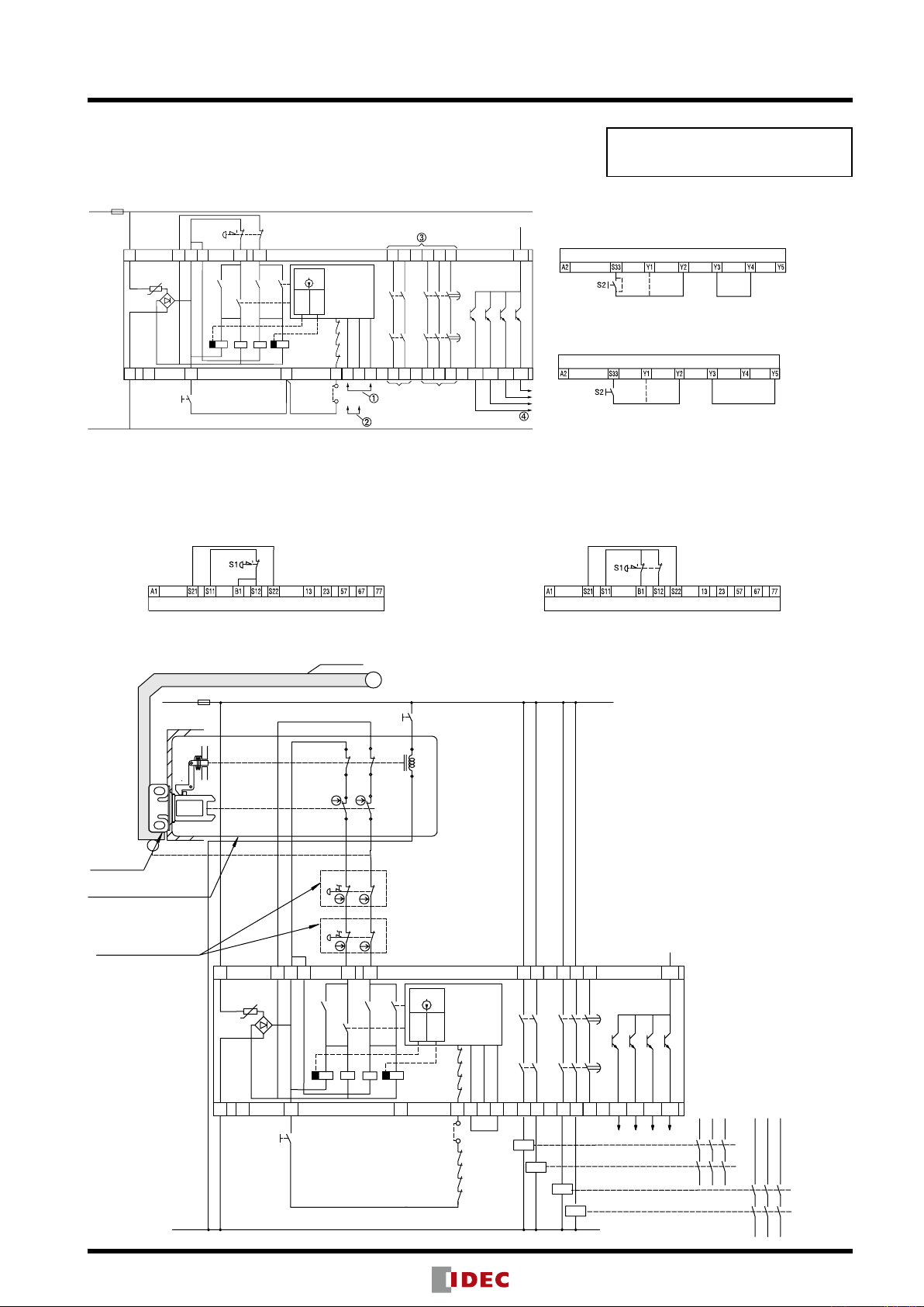
HR1S-ATE Wiring Diagram
Safety Category 4 (3) Circuit•
(using an emergency stop switch) (Note)
Safety•Category 3 Circuit (using multiple emergency stop switches)
Emergency stop switch - Input 2 channels•
When not detecting short-circuit
(B1-S12 short-circuit not detected)
Emergency stop switch - Input 1 channel•
When not detecting short-circuit (All failures such as short-
circuit of emergency stop switch wiring not detected)
When monitoring the start switch•
(Y3-Y5 short-circuited)
When not monitoring the start switch•
(Y3-Y4 short-circuited)
(automatic start when S33-Y2 is short-circuited)
S2
S1
S11S21
A1 13 57 67
A2
S33
Y1
Y2 Y3 Y4 Y5 14 24 6858
S22
B1
S12
23
F1
K2 K4
K1
K1
K3
L1 (+)
N(–)
K3
K4
K1
K2
Timer 1
Time (s)
Timer 2
T
ESC
K1
K2
K3
K4
HR1S-ATE
LOGIC
77
78 Y88 Y89 Y90 Y91
Y+
(A1/A2)
(S12)
(S22)
(Stop 1)
+24V
(max. 4A)
Stop
Category 0
Stop
Category 1
K2
HR1S-ATE
HR1S-ATE
HR1S-ATE
HR1S-ATE
When monitoring the start switch, starts when switched off (default setting/recommended)
When monitoring the start switch, starts when switched on
Outputs must be fused (see the instruction manual for maximum fuse size)
To PLC, etc.
Note: When using off-delay output, safety category becomes 3.
S1 = Emergency stop switch with 2 NC contacts (recommended)
S2 = Start switch
ESC = External start conditions
Y1 (S33)– Y2 = Feedback loop
S4
S11
S21
A1 13 57 67
A2
S33
Y1 Y2 Y3 Y4 Y5 14 24 6858
S22
B1
S12
23
K2 K4K1
K1
K3
N(–)
K3
K4
K1
K2
Timer 1
Time (s)
Timer 2
T
ESC
K1
K2
K3
K4
HR1S-ATE
LOGIC
77
78 Y88 Y89 Y90 Y91
Y+
(A1/A2)
(S12)
(S22)
(Stop1)
+24V
K2
L1 (+) F1
S3 21
22
11
12
S2 21
22
11
12
A2(+)
22
21
11
42
A1(–)
S1
2
1
1
2
S5
S6
52
41 51
12
Door Cover
K5
K6
K7
K8
K5
K6
K7
K8
External Output Circuit
S1:HS5E-D4001 Interlock Switch with Solenoid
S2, 3:XW1E-BV402 Emergency Stop Switch
S4:Start Switch (HW series momentary)
S5:Unlocking Enabling Switch
S6:Limit Switch, etc.
ESC:External Start Condition
K5 to 8:Contactor (forced guided type)
F1:Fuse 4A (gG)
Operations of Interlock Switch with Solenoid
(Stop)
Machine stops →Unlocking enabling switch ON →
Safety output OFF →Door cover released
(Start)
Door cover closed →Safety relay module start switch ON
→ Safety output ON →Machine starts
Operations of Emergency stop switch
(Stop)
Press emergency stop switch →Safety output OFF →
Machine stops
(Reboot)
Emergency stop switch reset →
Safety relay module start switch ON →Safety output ON
→Machine starts
Read instructions before configuring circuits.
HS5E-D4001
Interlock Switch with Solenoid
XW1E-BV402
Emergency stop switch
HS9Z-A51
Actuator
Safety category is achieved by an entire control
system. Take the connected safety equipment
and wiring into consideration.
(100705)

Power ON
With Start Switch
Output
Emergency Stop Switch (NC1)
➀
➀
When monitoring the start switch,
with Y3-Y5 jumpered
(default setting/recommended)
Operation
ON
Tv = 0 to 30 seconds
adjustable
OFF
➁
When monitoring the start switch,
with Y3-Y4 jumpered
➁
Emergency Stop Switch (NC2)
Output 13-14 (NO)
Output 23-24 (NO)
Output 57-58 (NO)
Output 67-68 (NO)
Output 77-78 (NO)
Start Switch
Start Switch
Start Switch
External Start Conditions
Transistor Output Y89 (S12)
Transistor Output Y89 (S12)
Transistor Output Y90 (S22)
Transistor Output Y90 (S22)
Transistor Output Y88 (A1/A2)
Transistor Output Y91 (Stop1)
Start
Emergency Stop
Not Operated
Emergency Stop
Operated
Without Start Switch
Emergency Stop Switch
(NC2 or NC1)
Emergency Stop Switch
(NC1 or NC2)
tmax.= 75ms∗
➂➂
Without start switch,
with Y3-Y4 and S33-Y1 jumpered
∗When using without start switch,
the input synchronization time
should be 75 ms max.
HR1S-ATE Operation Chart
HR1S-ATE Safety Relay Modules
Residual Risk (EN ISO/ISO12100-1)
The wiring diagrams on page 3 have been tested under actual
operating conditions. The HR1S-ATE safety relay module can be
used in a safety circuit by connecting to safety equipment compli-
ant to applicable standards. Consider residual risk in the following
circumstances:
a) When it is necessary to modify the recommended circuit and if
added/modified components are not properly integrated into the
control circuit.
b) When applicable standards of machine operation are not observed,
or when the machine is not adjusted or maintained properly
(adhere to a strict maintenance schedule).
c) When the contacts of relays and contactors for connected with
safety outputs are not forced guided (compliant with EN 50205).
Instructions
Only persons with technical expertise may install, startup, modify,•
or retrofit the HR1S-ATE safety relay module.
Turn the power off before installation, removal, wiring, mainte-•
nance, or inspection of the safety relay module. If an error occurs,
line voltage may be present at the control circuit in devices without
DC isolation.
Observe all electrical safety regulations issued by appropriate•
technical authorities or trade association. The safety function can
be lost if the device is not used for its intended purpose.
Do not open the housing or perform invalid operation, otherwise•
the warranty will become voided.
Negligence to observe the following instructions may cause ac-•
cidents that may result in death or serious injuries.
Connect the wires according to the wiring diagrams shown on⋅
page 3.
Connect the wires according to applicable standards.⋅
The contacts of relays and contactors to connected with safety⋅
outputs must be forced guided (compliant with EN 50205).
For external fusing, use an appropriate fuse size and connect ac-⋅
cording to the wiring diagram on page 3.
When maintaining or adjusting machines, observe the mainte-⋅
nance schedule.
If the recommended circuit is modified or if components are⋅
added/modified, make sure that they are properly integrated into
the control circuit.
Relays must have mechanically-linked contacts.⋅
Follow required standards applicable to the operation of the ma-⋅
chine. When maintaining or adjusting machines, observe a proper
maintenance schedule.
Do not use the module if it has been subjected to improper or•
incorrect use. In this case, the warranty will be voided.
Do not use the HR1S-ATE under stressful conditions such as ir-•
regular voltage, current, temperature, or humidity.
Before starting up your equipment for the first time, be sure to•
check all safety functions according to regulations and observe
the specified test cycles for safety equipment.
Perform the following precautionary steps prior to installation, as-•
sembly, or disassembly of the system.
1. Disconnect the supply voltage to the equipment / system prior to
starting work.
2. To prevent accidental activation of the module or system, per-
form lock-out or tag-out.
3. Make sure that no voltage is applied.
4. Ground N (–) as shown in the wiring diagram on page 3.
5. Protect against adjacent operating components using guards or
barriers.
6. The devices must be installed in a cabinet with a protection class
of at least IP54.
Contact Protection•
Type of protection according to EN/IEC 60529
Housing / Teminals: IP40 / IP20
Finger-safe protection according to EN 50274
Connect external fuse according to the wiring diagram on page 3.•
Output Contact Electrical Life
(Safety Circuit, Time-delay Circuit, Auxiliary Circuit)
Operating Current × 0.1A
Operations
AC15:
230V
AC1:
230V
DC1: 24V
DC13: 24V
(<0,1Hz)
7-31, Nishi-Miyahara 1-Chome, Yodogawa-ku, Osaka 532-8550, Japan
Tel: +81-6-6398-2571, Fax: +81-6-6392-9731
E-mail: [email protected]
Specifications and other descriptions in this catalog are subject to change without notice.
Cat. No. EP1318-0-2 JULY 2010 PDF
IDEC ELECTRONICS LIMITED
IDEC ELEKTROTECHNIK GmbH
IDEC (SHANGHAI) CORPORATION
IDEC (BEIJING) CORPORATION
Tel: +86-10-6581-6131
IDEC (SHENZHEN) CORPORATION
Tel: +86-755-8356-2977
IDEC IZUMI (H.K.) CO., LTD.
IDEC TAIWAN CORPORATION
Tel: +886-2-2698-3929 E-mail: service@tw.idec.com
IDEC IZUMI ASIA PTE. LTD.
www.idec.com
IDEC CORPORATION (USA)
Tel: +1-408-747-0550 / (800) 262-IDEC (4332)
E-mail: [email protected]
IDEC CANADA LIMITED
Tel: +1-905-890-8561, Toll Free: (888) 317-4332
E-mail: [email protected]
IDEC AUSTRALIA PTY. LTD.
Tel: +61-3-9763-3244, Toll Free: 1800-68-4332
E-mail: [email protected]
Other manuals for HR1S-ATE
2
This manual suits for next models
2
Other IDEC Relay manuals

IDEC
IDEC EB3N User manual

IDEC
IDEC HR1S-AC User manual

IDEC
IDEC LD6A Series User manual

IDEC
IDEC HR1S-ATE User manual

IDEC
IDEC HR1S-AF 5130B/PB User manual

IDEC
IDEC HR1S-DMB Series User manual

IDEC
IDEC EB3N User manual

IDEC
IDEC HR1S-AK User manual

IDEC
IDEC SmartAXIS FT9Z-1A01 User manual

IDEC
IDEC SmartRelay FL1A-H12RCE User manual


