IDQ id100-MMF100 User manual

ENS LYON
FROM VIS]ON TO îÊCHI.IOLOGV
REDEFINING PRECISION
id100-MMF100 Single Photon Detection Module: Operating Guide
We thank you for choosing our product" For questions please contact: [email protected].
This document explains how to use the id100-MMF100 single photon detection module and briefly introduces its mode of
ooeration.
The id100-MMF100 is a modified version of ourstandard device id100-MMF50. The id100-MMF100 contains a multi-mode
fiberwithacoreof l00pmandacladdingofla0flrn. Thetypicalcouplingefficiencyis50%.
GETTING STARÏED
Accessories supplied:
- single photon detection module (t)with
-four mounting brackets (z)
- 1m coaxial cable with BNC and SMB connectors (3)
- power supply (+) with universal range of input plugs (5)
- this operating guide
- angled T'10 Torx key (o)
Warnings:
Use onlythe power supply delivered with the id100-MMF100.
Please note thatthe power supply is for indoor use only.
The power supply should be disconnected from the mains when not in use.
Do not plug in the power supply in case of damaged cabinet or power plug"
Never open the power supply.
Preoaration for use and safetv:
Before starting to use the id100-MMF100, the input plug f) (corresponding to the mains) has to be placed on the power
supply. The polarity inverter @ must be connected as shown below
Connect the SMB coaxial cable termination to the id100-MMF100 single photon detection module@.
Connect the BNC termination to the measurement device: oscilloscope, counter, correlator, timeto-digital converter, time-
to-amplitude converter, etc. To limit ringing and signaldistortions, the id100-MMF100 output should be terminated with a
50O load.
Connect the power supply jack to the DC6V input at the rear panel of the id100-MMF100 module(9.
Connect the input plug to the mains.
When properly connected, the id'100-MMF100 is usable immediately. No time delay for cooling or stabilization is required.
BNc conneclor (mâe)
fi rsr
ro
t
m
m
t
rî\
r.z) I
--tYrrru-
3+llllllllll ---__r
---1__xL[]Il_[___i
Your id100-MMF100 single photon detection module may slighlty differ from this illustration.

By default, the id100-MMF100 is equipped with four mounting brackets. The brackets accept screws with diameters up to 4mm
However, a bracketcan be removed by:
- unscrewing f, using the TORX key while maintaining the id 100-MM F100 closed,
- removing the bracket keeping the plastic joint C in place,
- screwing f, back.
Please remove one bracket at a time.
angled T10 TORX key
i
mounting bracket
When the module is not being used, the protective cap should be fitted over the detector port.
OPERATION
The id100-MMF100 consists of an avalanche photodiode (APD) and an active quenching circuit integrated on the same silicon
chip. The chip is mounted on a thermo-electric cooler and packaged in a standard TO5 header with a transparent window cap.
A multimode fiber is pigtailed on the TO-header. The fiber is terminated by a FC/PC connector. Athermistor is used to measure
temperature. TheAPD is operated in Geiger mode, i.e. biased above breakdown voltage. Ahigh voltage supply used to biasthe
diode is provided by a DC/DC converter. The quenching circuit is supplied with +5V. The module output pulse reflects the
arrival of a photon with high timing resolution. The pulse is shaped using a hold-off time circuit and sent to a 50O output driver.
All internal settings are preset for optimal operation at room temperature. No user adjustement is necessary.
F
c
ft
U]
FC/PC connector
mounting brackets
mounting brackets
Block diagram of the idlùA-MMFI00.

FROM VISION TO ÏECHNOLOGY
The figure opposite shows a typical pulse observed at the output of the id100-
MMF100 terminated with a 50fi load. A2V amplitude and 10ns width is available.
The recommended trigger level of the measurement device is 1V.
For "pure" counting applications, the trigger slope can be negative or positive.
For timing applications, the trigger slope must be positive in order to take full
advantage of the id100-MMF100 timing resolution. 1ons
,ê
MAINTENANCE
Maintain a temperature range within specifications when transporting or storing the unit. Transportation damage can occur
from improper handling. The following steps are recommended to minimize the possibility of damage:
- pack the unit in the original packing material when shipping.
- store unit at room temperature in a clean and dry area.
- avoid high humidity or large temperature fluctuations.
- keep the unit out of direct sunlight.
- avoid unnecessary shock and vibration.
The following safety precautions must be observed during the operation and servicing of the unit. Failure to comply with these
precautions or with specific indications elsewhere in this manual violates safety standards of intended use of the unit. lD
Quantique assumes no liabilityforthe user's failure to comply with these requirements.
- This unit is intended for indoor use only.
- Unit covers cannot be removed during operation.
- Any adjustments, maintenance, and repair of opened unit under voltage should be avoided and carried out only by
skilled personnel aware of the hazards involved. Do not attempt internal service or adjustment unless another person qualified
in first aid is present. Do not replace any components while power cable is connected.
- Operation of any electrical instrument around flammable gases orfumes constitutes a major safety hazard.
- Installation of replacement parts or modification of the unit should be carried out by authorized personnel only.
There are no user-serviceable components in the id100-MMF100. The id100-MMF100 has been designed to require minimum
maintenance and to provide reliable operation for many years to come.
To help ensure long, trouble-free operation,
- Keep the id100-MMF100 free of dust
- Do not spill liquids on or into the unit. lf the unit does get wet, turn off the power immediately and let the unit dry
completely.
To ensure optimum performance, the optical port should be kept as clean as possible. lt is recommended to connect before the
first use of the detector an optical fibre patchcord to the id100-MMF100 optical input port. This patchcord should then be used
for all connections of the module to a device under test" ln case of inappropriate insertion losses, the end connector of this
patchcord can be easily cleaned by the user.
Nevertheless, if the optical port needs to be cleaned,
1 .Remove the protective cap
2.lnsert a lint-free stick dipped in isopropyl alcohol and gently wipe the receptacle
3.Dry using a dry lint-free stick.
The patchcord fibre ends connected to the id100-MMF100 optical input port must be kept clean at alltimes to ensure minimum
loss and to reduce reflection.
LGently wipe the fibre end with a lint-free swab dipped in isopropyl alcohol (98% pure or better).
2.Dry using clean compressed air.

WARRANTY & LIABILITY
lD Quantique warrants this equipment against defect in material and workmanship for a period of twelve months from the
date of original shipment. lD Quantique also warrants that this equipment will meet applicable specifications under normal
USC.
During the warranty period, lD Quantique will, at its discretion, repair, replace, or issue creditfor any defective product.
The warranty can become void if:
the equipment has been tampered with, repaired, or worked upon by unauthorized individuals or non-lD Quantique
personnel,
or ifthe case has been opened,
or if the equipment serial number has been altered, erased, or removed,
or if the equipment has been misused, neglected, or damaged by accident.
THISWARRANTY IS IN LIEU OFALLOTHERWARRANTIES EXPRESSED,IMPLIED ORSTATUTORY INCLUDING, BUT
NOT LIMITED TO. THE IMPLIED WARRANTIES OF MERCHANTABILITY AND FITNESS FOR A PARTICULAR
PURPOSE. lN NO EVENT SHALL lD Quantique BE LIABLE FOR SPECIAL, INCIDENTAL, OR CONSEQUENTIAL
DAMAGES.
lD Quantique shall not be liable for damages resulting from the use of the purchased product, nor shall be responsible for any
failure in the performance of other items to which the purchased product is connected orthe operation of any system of which
the purchased product may be a part.
lD Quantique reserves the right to make changes in the design or construction of any of its products at any time without
incurring any obligation to make changes whatsoever on units purchased.
GENERAL SPECIFICATIONS AT ROOM TEMPERATURE
Parameters Minimum Typical Maximum Units
Spectral range
Timing resolution IFWHM]
Photon detection probability
at 400nm
at 500nm
at 600nm
at 700nm
at 800nm
at 900nm
Afterpulsing probability
0utput pulse width
Output pulse amplitude
Dead time
Maximum count rate (pulsed light)
Supply voltage
Supply current
Storage temperature
Cooling time
900
60
nm
ps
40
15 18
30 35
20 25
15 18
E7
34
%
Yo
%
Yo
ns
v
ns
MHz
V
mA
s
10
z
45
20
o
100
The id100-MMF100 is a modified version of our standard
device id100-MMF50. The id100-MMF100 contains a multi-
mode fiber with a core of 100pm and a cladding of 140 pm,
Thetypical coupling efficiency is 50%.
o
1.5
é
15
z,a
50
o.f,
150
70
3
Dark count rate: lD Quantique modules are available in two grades: Standard and Ultra-Low Noise,
depending on dark count rate specifications.
TE cooled Standard Ulka-Low Noise
idl00-MMF100 yes < 80Hz <20H2
The information and specification sêtforth in this document are subjectto change at any time by lD Quantique wilhout prior notice.
Copyrjghto2005-201 2 lD Quantique SA - All rights reserved - id1 00-MMF100 Operating Guide v3.3 - January 201 2
Popular Control Unit manuals by other brands

BYOC
BYOC Crown Jewel Hard Clipper instructions

Viessmann
Viessmann VITOTRONIC 300 Technical data manual
Lütze
Lütze DIOLINE PLC operating instructions
Victaulic
Victaulic FireLock NXT 769N Series Installation, Maintenance, and Testing Manual

Lütze
Lütze LION microPLC operating instructions
DeZurik
DeZurik VPB V-PORT instruction manual

resideo
resideo Braukmann SG160S installation instructions
REXROTH
REXROTH IndraControl L25 operating instructions

WEG
WEG CFW500 Series Installation, configuration and operations guide
Gotop
Gotop GT-1613-MTGN manual
Vestamatic
Vestamatic Vesta Building Controller Installation and operating instructions
Intel
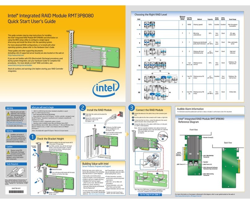
Intel RMT3PB080 Quick start user guide


