Vortec Vest-L Use and care manual

Please read all instructions BEFORE attempting to use this product
IMPORTANT
VORTEC COOLING VEST
AND COOLING TUBE
OPERATION & SAFETY
INSTRUCTIONS
Pelmar Engineering Ltd.
Tel. (888) 754-6329, (416) 288-1736
E-mail: [email protected]
Web site: www.pelmareng.com

WARNING: COMPRESSED AIR COULD CAUSE DEATH, BLINDNESS
OR INJURY
1. Do not operate a Cooling Vest or Cooling Tube at air pressures above 150 psig (10.3 Bar).
2. Do not operate a Cooling Vest or Cooling Tube at compressed air temperatures above 90°F (32°C).
3. Avoid direct contact with compressed air.
4. Do not direct compressed air from a nozzle or orifice at any person.
5. When using compressed air, wear safety glasses with side shields.
Introduction
Vortec Cooling Tubes are designed to be used with Vortec Cooling Vests to provide worker comfort in
extreme temperature environments. The vortex tube technology utilized in the Cooling Tube uses filtered
compressed air to focus chilled air on the user’s torso through the Cooling Vest. With no moving parts, and
under reasonable care, the Cooling Tubes and Cooling Vests will provide years of trouble-free operation.
Compressed Air Supply
The compressed air supply must be filtered (5 micron maximum) to remove water and dirt. If oil is present
in the compressed air supply, remove the oil using a 0.01 micron (maximum) coalescing filter. Filter
recommendations are given in Table 1.
Filter elements must be changed on a regular basis. Frequency of change is determined by the condition
of the compressed air supply. Filters should be installed (fixed to a wall or rigid piping) so that they remain
in an upright position with the bowl drain pointing downward. All recommended filters have an automatic
drain feature, so all condensation will automatically be expelled from the bottom of the filter when the bowl
reaches capacity. The filter should be located as close as possible to the Cooling Tube, so use the shortest
hose possible to prevent excessive pressure drop.
The appropriate size of compressed air hose should be selected to ensure optimal performance of
the Cooling Tube. Please refer to Table 2 to determine the proper compressed air hose size for your
application. Contact Vortec at 1-800-441-7475 for further assistance. If the Cooling Tube is used to provide
cool respirable air to a hood or helmet, then the compressed air supply must meet stringent conditions for
oxygen content and other factors. (Refer to the respirator manufacturer’s instructions.)
All of Vortec’s Cooling Tubes utilize a standard ¼” Industrial Interchange quick connect nipple to allow for
easy attachment to and detachment from compressed air hoses.
Operation
Cooling Tube
The Cooling Tube can be used to provide a chilled air supply to the user. The temperature and flow rate of
the cold air stream can be adjusted over a wide range by turning the black muffler on the end of the Cooling
Tube: turning the muffler counterclockwise reduces the temperature and flow of the cold air. Turning the
GENERAL SAFETY CONSIDERATIONS

muffler clockwise will increase the temperature and flow of the cold air. The black muffler may become
warm. An optional heat shield is available to protect the user’s body from the hot exhaust air, if desired.
(See Table 1).
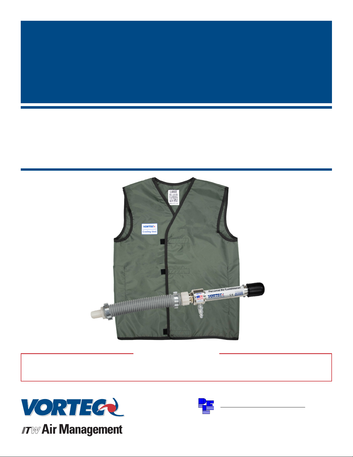
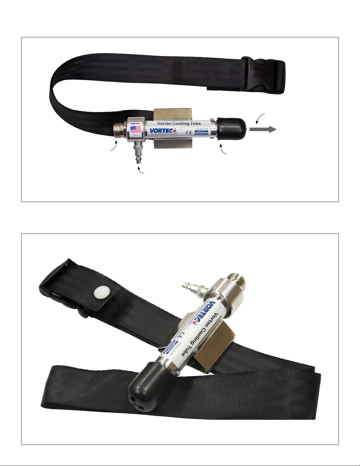
The Cooling Tube can supply chilled air to the Vortec Cooling Vest or to a hood or helmet. When purchased
with the vest, the cooling tube is inserted into a sleeve on the vest; when purchased separately, the Cooling
Tube is supplied with a belt, with the Cooling Tube in a horizontal orientation on the user’s waist. If it
is desired to reposition the Cooling Tube so that it is vertical on the waist (for connection to a hood or
helmet), first remove the white plastic button at the end of the belt by pulling the two halves apart. Remove
the belt assembly from the metal belt bracket and then reattach it to the bracket through the alternate
slots. Loop the end of the belt through the male side of the buckle and reattach the white button in the belt
hole by pushing the two halves together. See Figures 1 and 2.
Cooling Vests
Upon receipt, inspect the vest and contact your Vortec representative immediately if you suspect
damage of any kind to the vest. Once the vest is placed into service, it may not be returned under any
circumstances. The Cooling Vest comes with the Cooling Tube already inserted into the sleeve on the vest.
Put the Vest on, and secure the front of the vest with the four Velcro fasteners. Be sure to leave enough
room to comfortably move in the vest. Connect the Cooling Tube to the air supply for cooling to begin.
The Cooling Vest may be used under welding leathers, coveralls or other protective garments, but the warm
exhaust air from the Cooling Tube must be vented outside of the garment.
Maintenance
The Cooling Tube may be disassembled for cleaning by removing the cold outlet fitting. Remove the O-ring
and the red, blue or brown nylon generator. Inspect the parts and clean or replace as needed (see Table 1
for replacement items). When reinstalling the components, it is important to torque the cold outlet fitting to
100 inch-pounds (11 newton meters) to ensure proper sealing. Check the filter elements in the compressed
air filter(s) and change if necessary.
Troubleshooting
Insufficient airflow may be caused by the following:
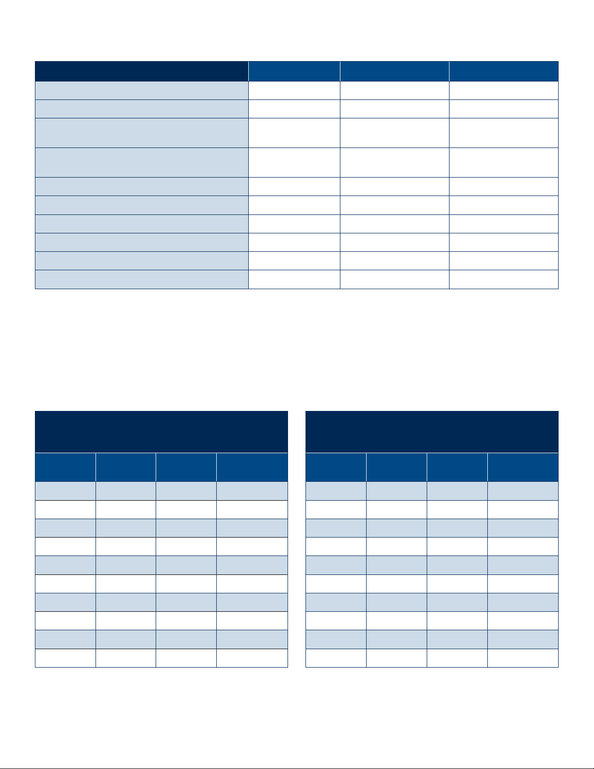
1. Undersized compressed air line size (See Table 2).
2. Compressed air hose too long (excessive pressure drop through hose).
3. Compressed air pressure too low.
4. Insufficient compressed air volume.
5. Partial or complete blockage of internal compressed air path, due to dirt or moisture freezing in the cold
air stream.
6. Loose cold outlet fitting (if disassembled for cleaning).
If trouble persists, please contact Vortec at 1-888-754-6329
Limited Warranty
Vortec compressed air products manufactured by ITW Air Management will be replaced or repaired if
found to be defective due to manufacturing within ten years of the date of invoice. Cooling Vests are not
covered under by this warranty if the vest has been removed from the packaging and placed into service.
Refer to our website www.vortec.com for full warranty details and limitations. ITW Air Management makes
no specific warranty merchantability or warrant of fitness to a particular purpose.

Figure 1: Vortec Cooling Tube with belt installed for horizontal orientation
Figure 2: Vortec Cooling Tube with belt installed for vertical orientation
Cold air outlet
(3/4” garden hose thread)
1/4” Industrial interchange
quick connect nipple
Temperature adjustment knob
Hot air exhaust

LIT0380
Table 1: Cooling Tube / Cooling Vest Model Number Matrix
VEST MODEL NUMBER MATRIX Cooling Vest (L) Cooling Vest (XL) Cooling Vest (2XL)
Cooling Tube with Belt Model Number 22825 22835 22835
Replacement Vest Model Number Vest-L Vest-XL Vest-2XL
Cooling Capacity 1500 BTUH
(378 kCal/hr)
2500 BTUH
(630 kCal/hr)
2500 BTUH
(630 kCal/hr)
Air Consumption 25 scfm
(708 slpm)
35 scfm
(990 slpm)
35 scfm
(990 slpm)
Recommended Air Filters:
5 Micron Air Filter Part Number 701S-24A 701S-36A 701S-36A
Oil Removal Part Number 701S-48 701S-48 701S-48
Replacement Parts and Accessories:
Heat Shield Part Number 228-80 228-80 228-80
Replacement Generator Kit Part Number* 208GK-25H 208GK-35H 208GK-35H
All specifications at 100 psig and 70°F (6.9 bar and 21°C) compressed air.
* A generator kit consists of five generators of the same specification.
Table 2: Determining Compressed Air Hose Size
1. Determine the product’s compressed air consumption from the information given in Table 1.
2. Determine the length of compressed air hose required for the application.
3. Locate the hose length in the left column and read to the right to find the compressed air consumption.
4. Locate the recommended hose size at the top of the column.
MAXIMUM AIRFLOW (SCFM) THROUGH
SMOOTH BORE HOSE
at a 5 psig pressure drop (100 psig and 70°F)
Hose Length
(feet)
3/8"
id hose
1/2"
id hose
3/4"
id hose
10 29 65 120
20 21 46 85
30 17 37 70
40 15 32 60
50 13 29 54
60 12 26 49
70 11 25 46
80 10 23 43
90 10 22 40
100 9 21 38
MAXIMUM AIRFLOW (SLFM) THROUGH
SMOOTH BORE HOSE
at a 0.3 bar pressure drop (6.9 bar and 21°C)
Hose Length
(meters)
10 mm
id hose
13 mm
id hose
20 mm
id hose
3 821 1840 3396
6 594 1302 2406
9 481 1047 1981
12 425 906 1698
15 368 821 1528
18 340 736 1387
21 311 708 1302
24 283 651 1217
27 269 623 1132
31 255 594 1075
Example:
A model 22825 Cooling Tube uses 25 scfm (708 slpm) of air. If a 50 foot (15 m) long hose is needed to supply air to the 22825, then the
inside diameter of the hose should be 1/2” (13mm).
This manual suits for next models
4
Table of contents
Other Vortec Accessories manuals
Popular Accessories manuals by other brands

Becker
Becker CentronicPLUS SC811 PLUS Assembly and operating instructions

QC Industries
QC Industries PF26 Conveyors Installation, operation & maintenance instructions

SIXTOL
SIXTOL SX4010 Instructions for use

LG
LG LRM2060ST - Countertop Microwave Oven installation instructions

Albrecht Audio
Albrecht Audio PB 52 manual

netvox
netvox R718AD user manual