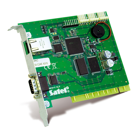
Satel VMG-16 User manual
Other Satel Control Unit manuals
Satel
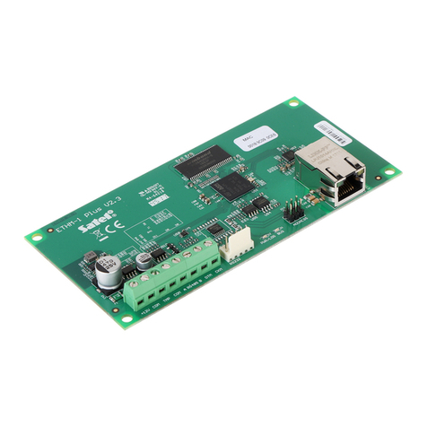
Satel ETHM-1 Plus User manual
Satel
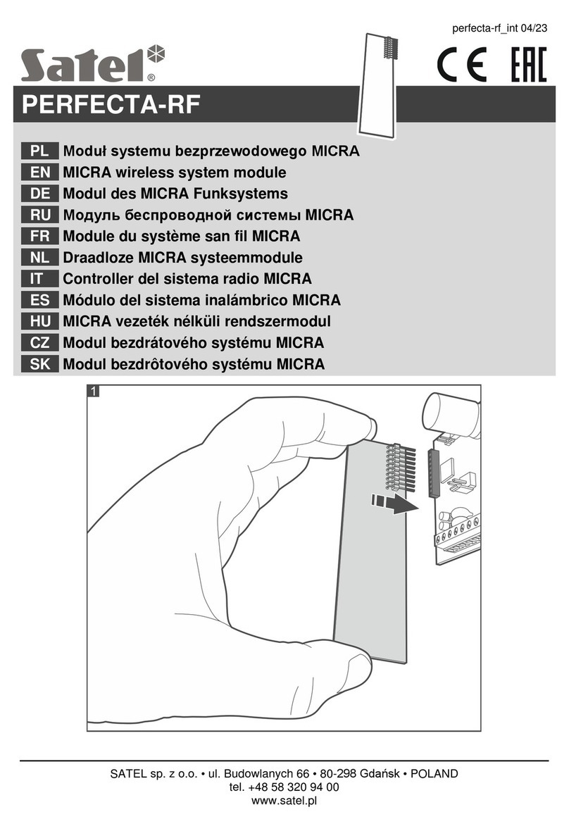
Satel SATEL-TR49 SnapOn Quick setup guide
Satel
Satel MICRA User manual

Satel
Satel CA-64 ADR-MOD User manual

Satel
Satel GSM LT-2 User manual

Satel
Satel GSM-4 User manual

Satel
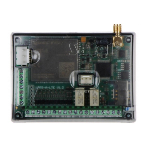
Satel ETHM-1 Plus User manual
Satel
Satel GPRS-A User manual

Satel
Satel PK-01 User manual

Satel
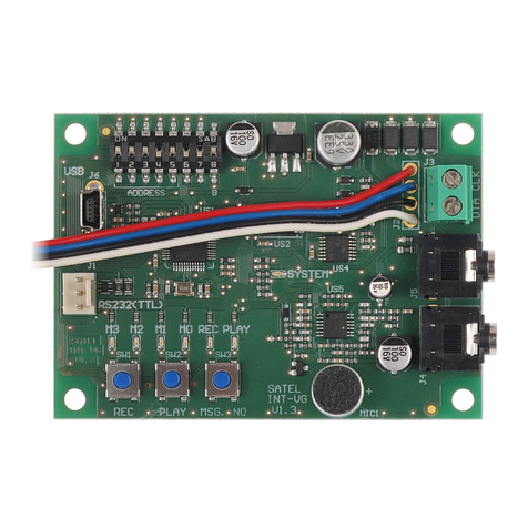
Satel INT-VG User manual
Satel
Satel INT-VG User manual
Satel
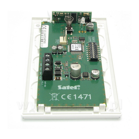
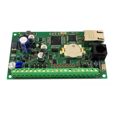
Satel INT-RX User manual
Satel
Satel ETHM-2 User manual
Satel
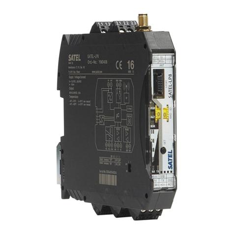
Satel SATEL-LP8 Quick start guide
Satel
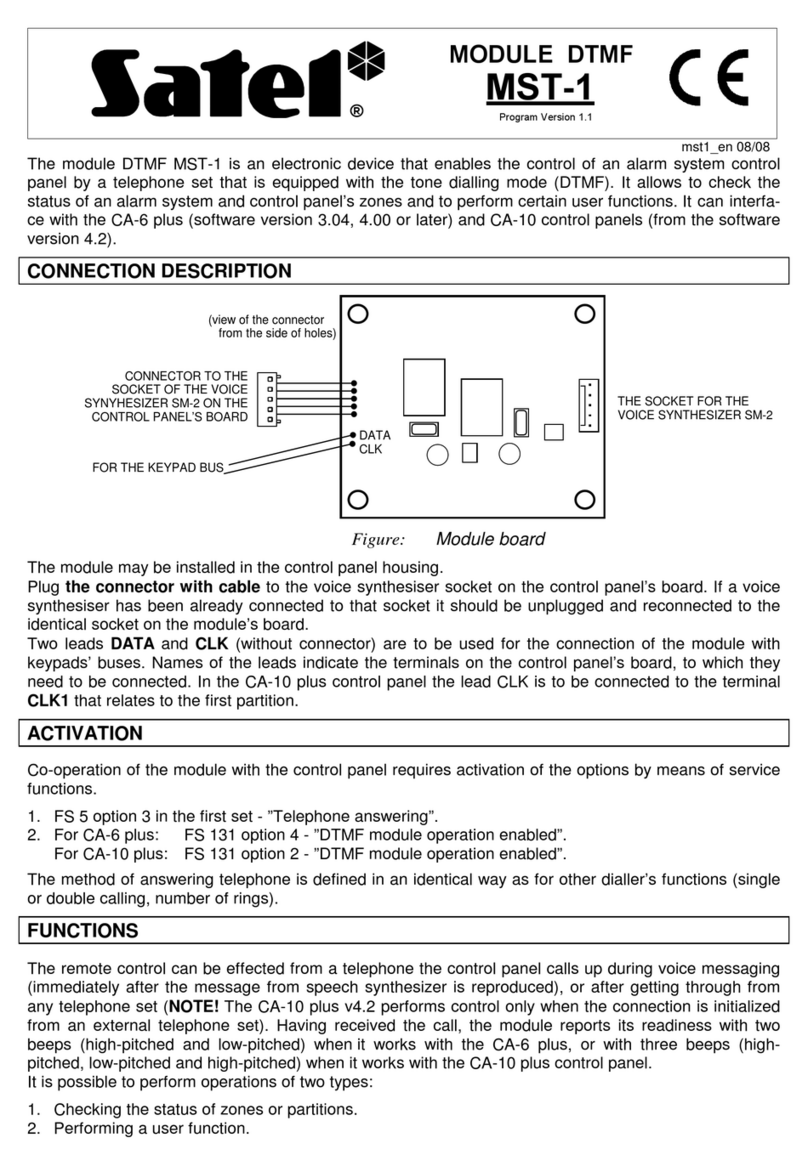
Satel MST-1 User manual
Satel
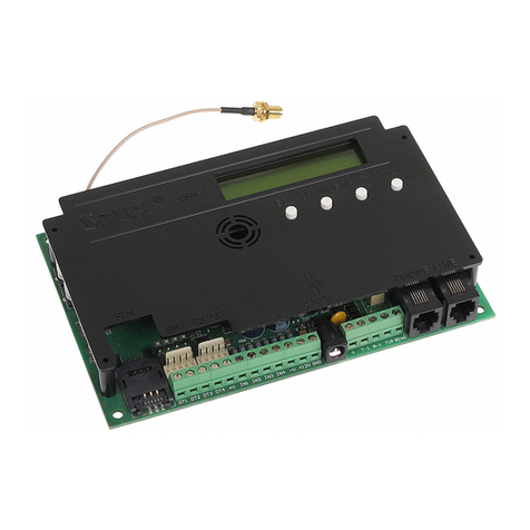
Satel GSM-4S User manual

Satel
Satel ETHM-1 Plus User manual

Satel
Satel GSM-X User manual

Satel
Satel ETHM-1 Plus User manual
Satel
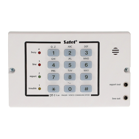
Satel DT-1 User manual
Popular Control Unit manuals by other brands

Festo
Festo Compact Performance CP-FB6-E Brief description

Elo TouchSystems
Elo TouchSystems DMS-SA19P-EXTME Quick installation guide

JS Automation
JS Automation MPC3034A user manual

JAUDT
JAUDT SW GII 6406 Series Translation of the original operating instructions

Spektrum
Spektrum Air Module System manual

BOC Edwards
BOC Edwards Q Series instruction manual

KHADAS
KHADAS BT Magic quick start

Etherma
Etherma eNEXHO-IL Assembly and operating instructions

PMFoundations
PMFoundations Attenuverter Assembly guide

GEA
GEA VARIVENT Operating instruction

Walther Systemtechnik
Walther Systemtechnik VMS-05 Assembly instructions

Altronix
Altronix LINQ8PD Installation and programming manual
