iDRY TURBO User manual

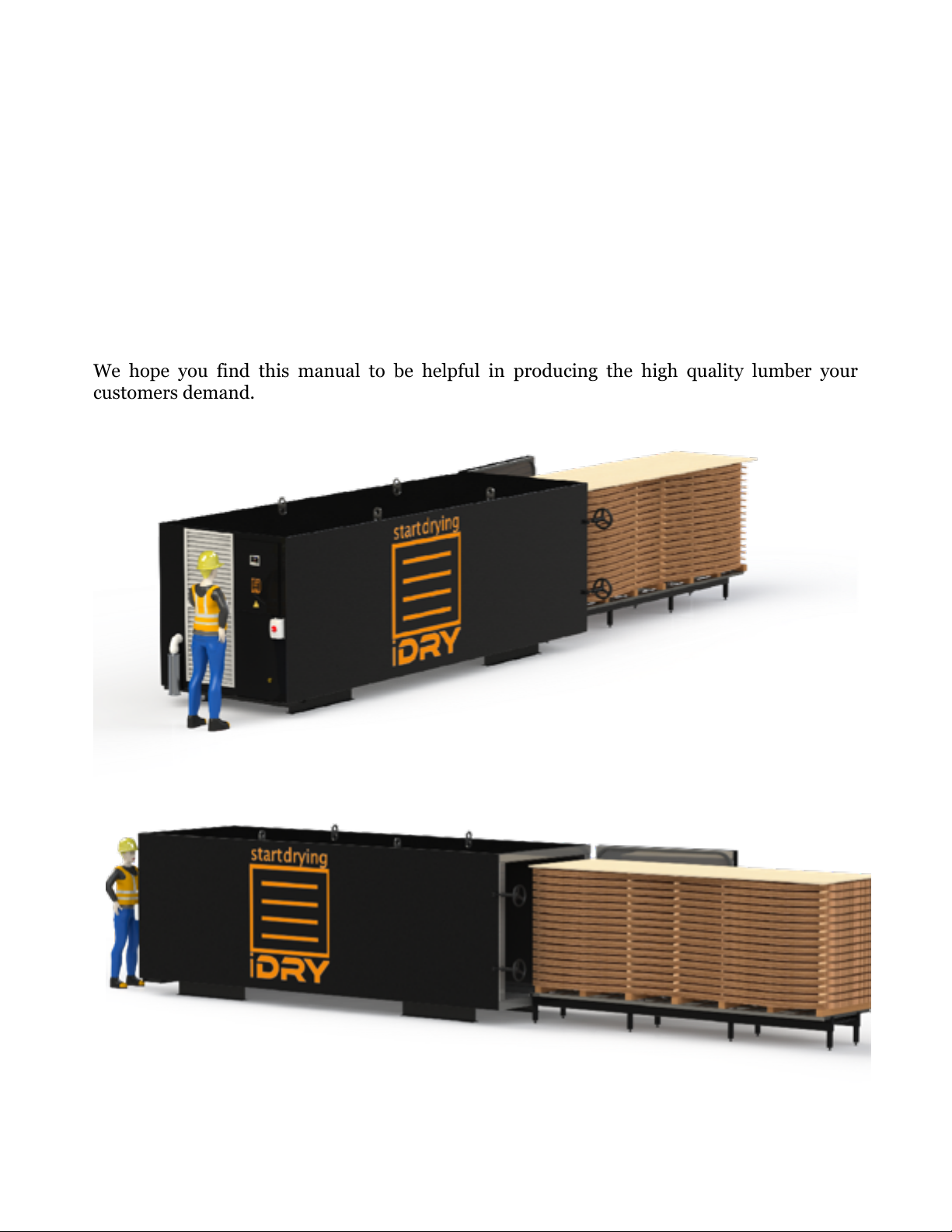
Introduction 4................................................................................................................
Safety 5...........................................................................................................................
Specifications - Turbo 5.................................................................................................
Specifications - Turbo MINI 6.......................................................................................
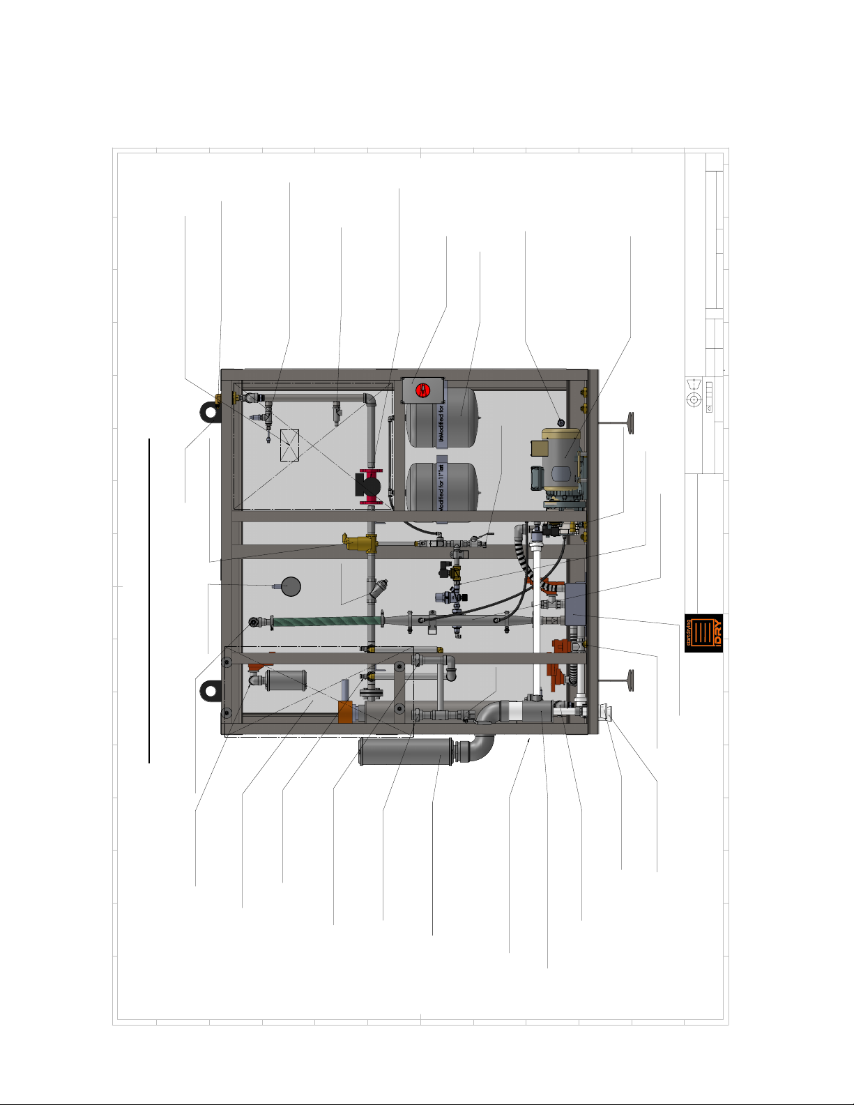
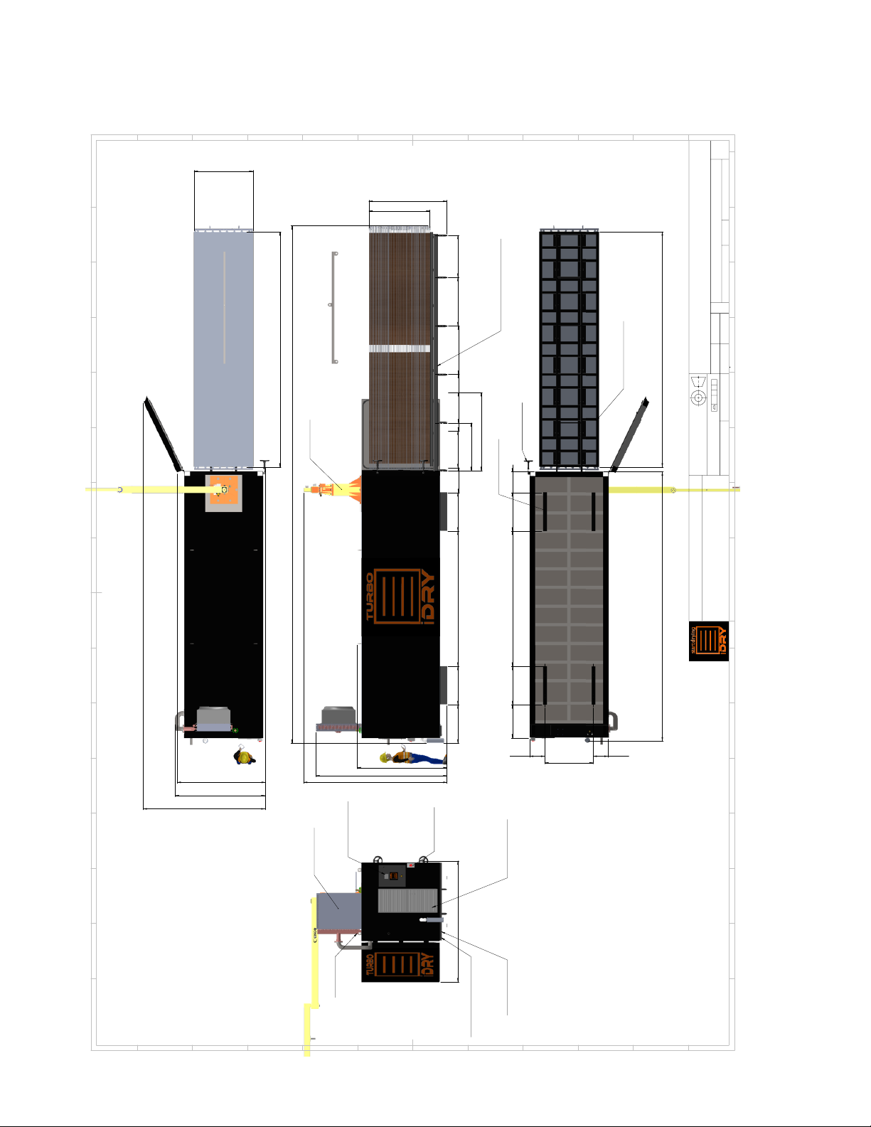
Technical Drawings - Turbo 7........................................................................................
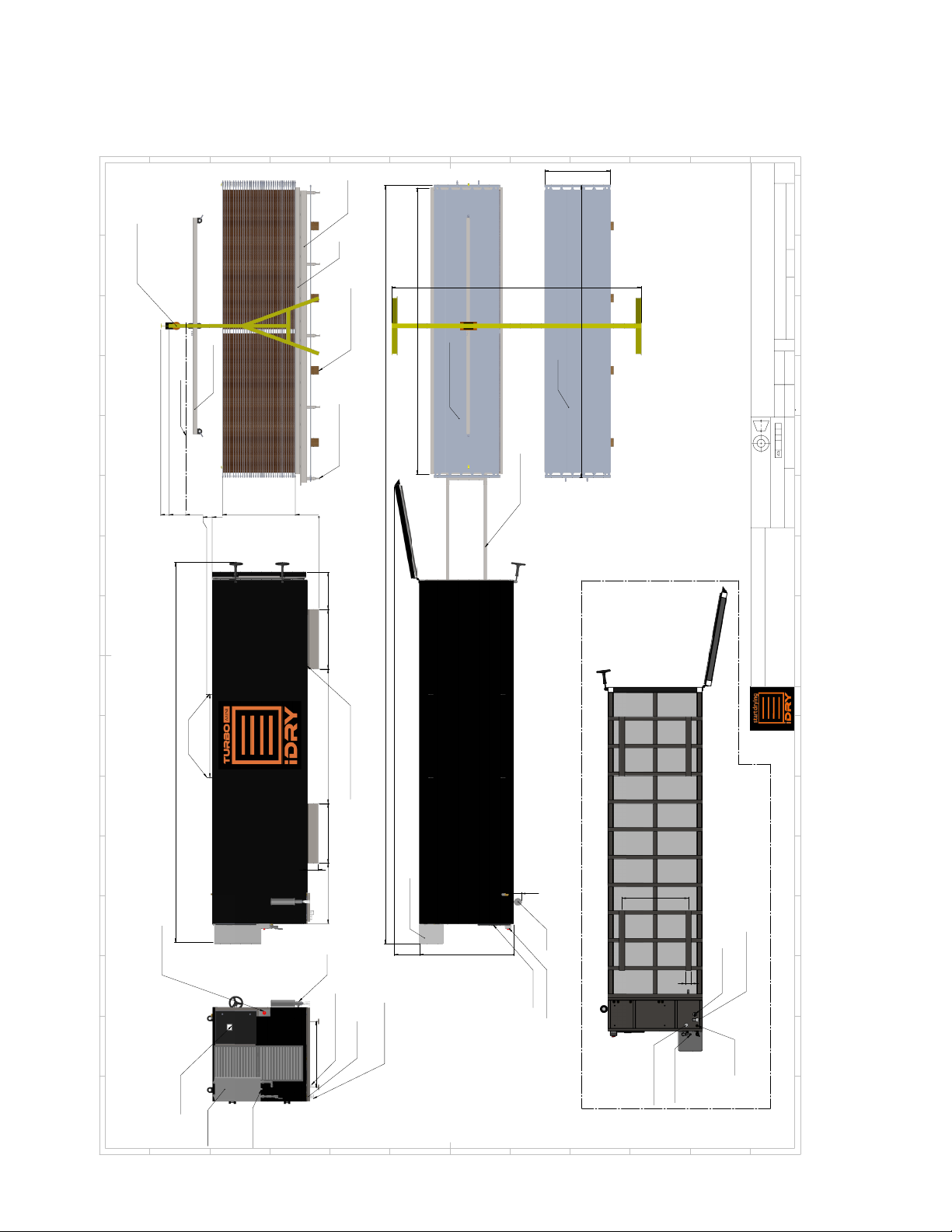
Technical Drawings - Turbo MINI 8.............................................................................
Technical Drawings - Turbo 9.......................................................................................
Technical Drawings - Turbo MINI 10...........................................................................
Installation & Startup: 11...............................................................................................
Placement 11........................................................................................................................
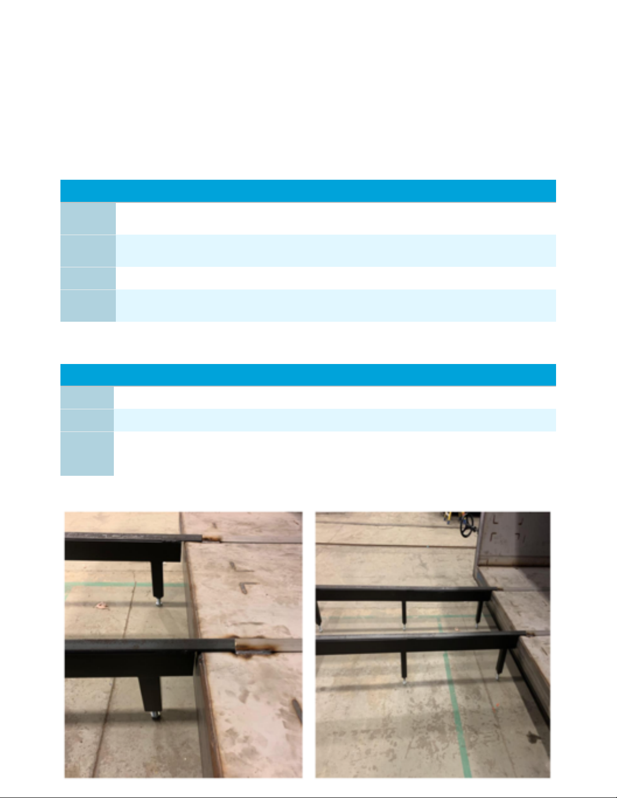
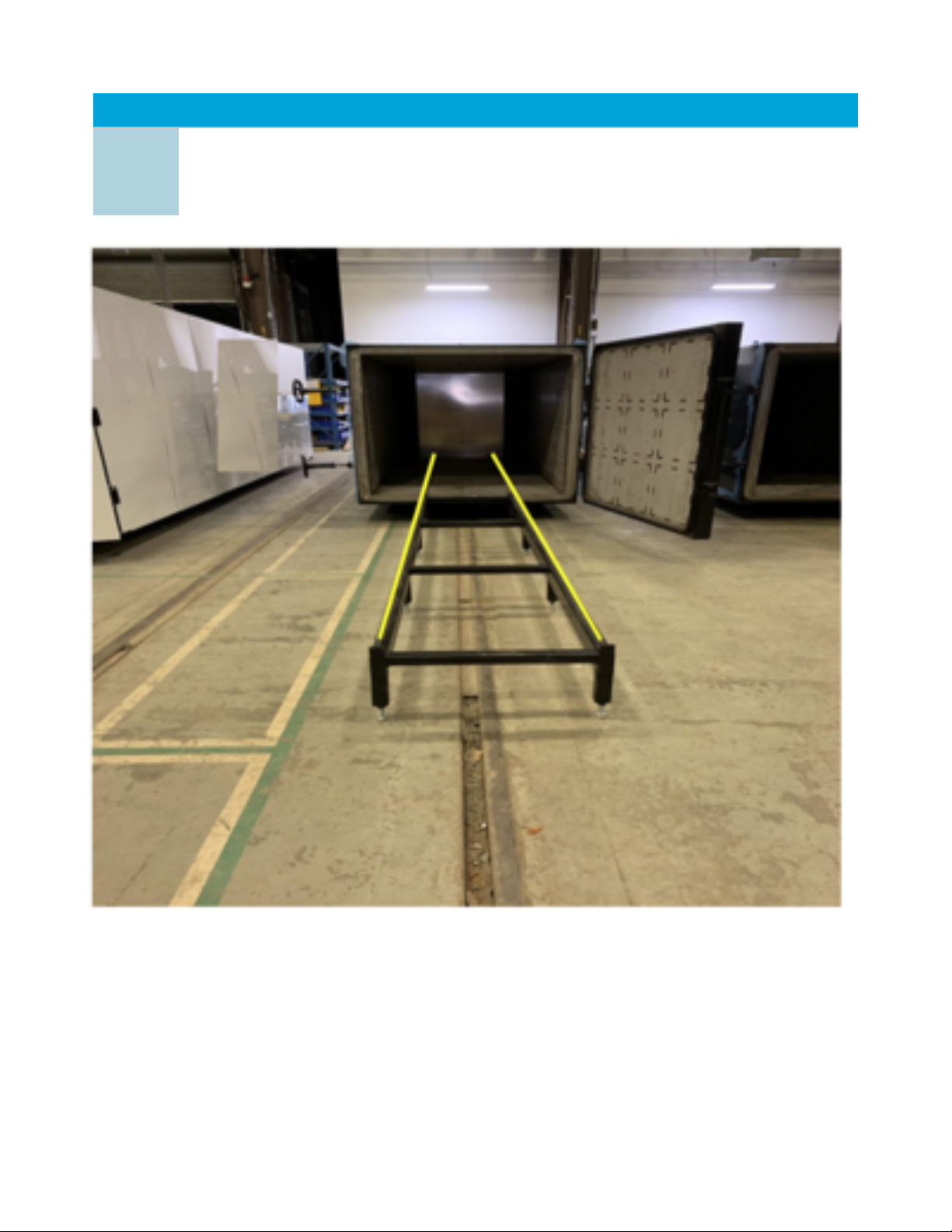
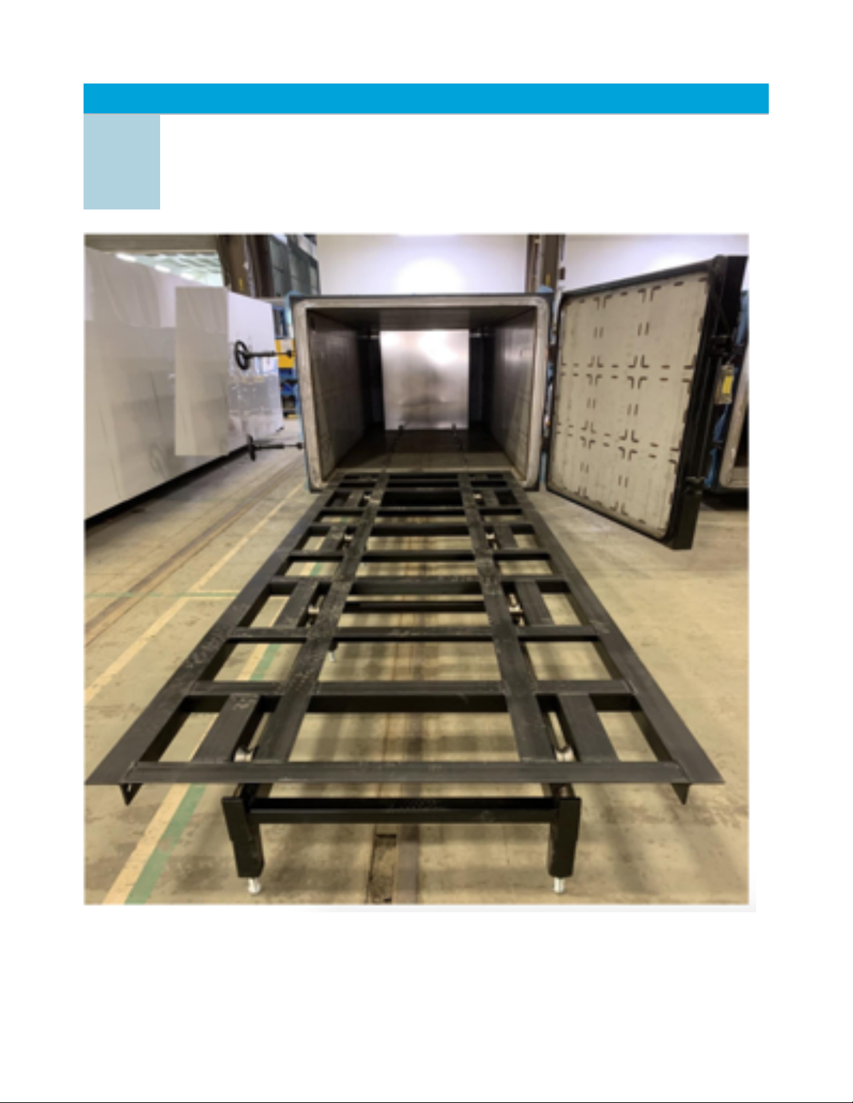
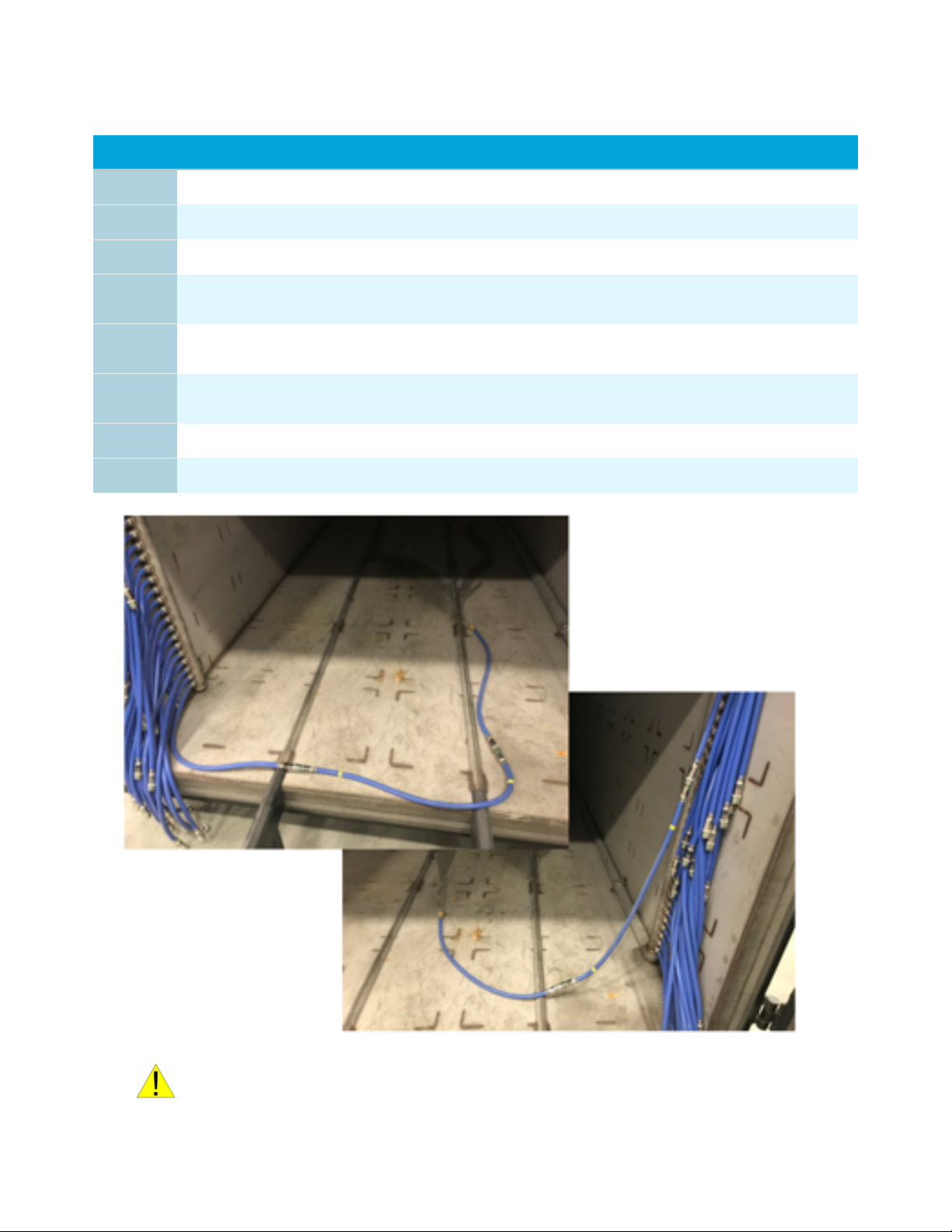
Track & Trolley Installation 11............................................................................................
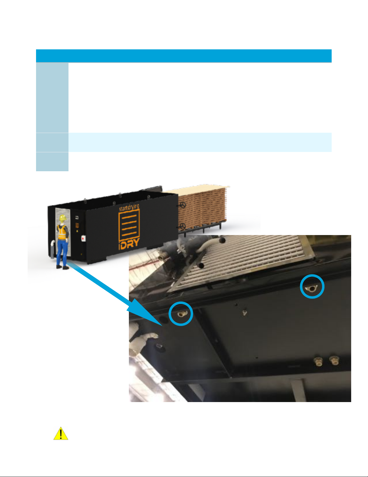
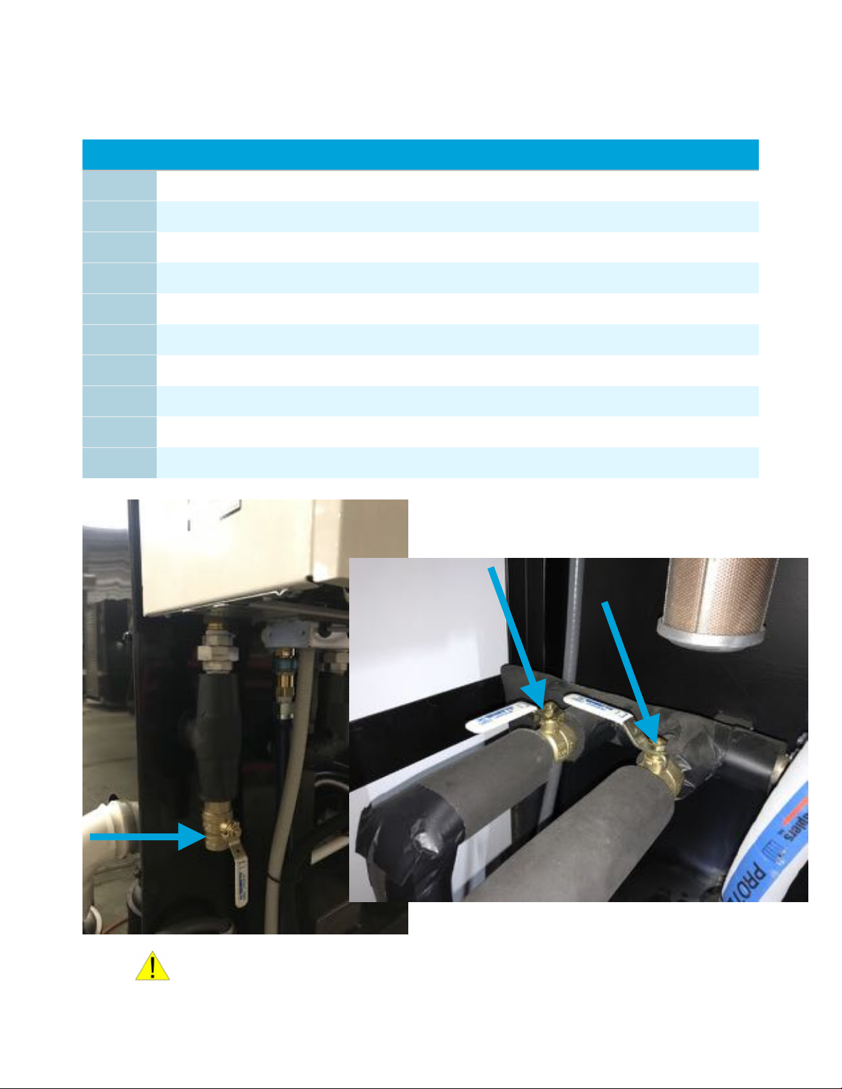
Plumbing 14.........................................................................................................................
Condenser - Turbo Only 15..................................................................................................
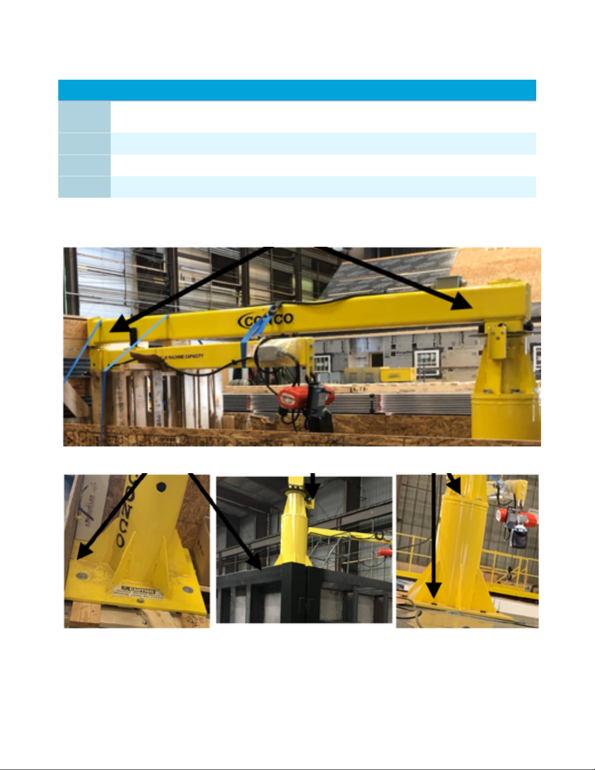
Jib Crane - Turbo Only 16...................................................................................................
Power 17...............................................................................................................................
Powering Up 18....................................................................................................................
Heating System Water Filling Procedure 19.......................................................................
Boiler Setup and water fill procedure - Gas Boiler Only 20...............................................
Heating Plates Water Filling Procedure 21.........................................................................
Water System Test 22..........................................................................................................
Using the Press Bladder 23.................................................................................................
Closing the Door 24.............................................................................................................
Starting the Kiln 25..............................................................................................................
Kiln Monitoring 25..............................................................................................................
Unloading the Kiln 26.........................................................................................................
Unloading the Kiln - Check Moisture Content 26..............................................................
SYSTEM SETUP 27........................................................................................................
TOOLS 27.............................................................................................................................
SCREEN #1 SETUP PARAMETERS 28..............................................................................
SCREEN #2 SETUP PARAMETERS 29..............................................................................
SCREEN #3 SETUP PARAMETERS 30..............................................................................
CORRECT USE 31..........................................................................................................
Lumber preparation 31........................................................................................................
Proper Stacking 31...............................................................................................................
iDRY Turbo User Manual
© 2021 iDRY, LLC
2

Reducing Degrade 31...........................................................................................................
Winter vs Summer 31..........................................................................................................
Initial Moisture Content 31.................................................................................................
Mixing Species 32................................................................................................................
Mixing Thickness 32............................................................................................................
Frozen Lumber 32...............................................................................................................
Drying Interruptions 32......................................................................................................
Troubleshooting 33........................................................................................................
Troubleshooting and Alarms 33..........................................................................................
Warning labels 36..........................................................................................................
Terms and Conditions 37...............................................................................................
iDRY Turbo User Manual
© 2021 iDRY, LLC
3

Introduction
Congratulations on your purchase of an iDRY Systems iDRY lumber dryer. This equipment is
a product of IDRY, LLC’s quality engineering and manufacturing. With a high quality rugged
stainless steel pressure vessel and state of the art electronics this iDRY dryer will, with
proper maintenance provide long term satisfactory service. To obtain the best use of your
iDRY dryer, please read this manual carefully. It will help you become familiar with the
operation of the equipment and contains helpful information regarding installation,
operation, maintenance and troubleshooting.
We hope you find this manual to be helpful in producing the high quality lumber your
customers demand.
iDRY Turbo User Manual
© 2021 iDRY, LLC
4

Safety
This equipment should be operated by trained personnel and maintained by certified
professionals. The equipment is intended for non-treated lumber only and should not be
used for any other purpose. Any modifications of the equipment or use of unauthorized parts
is forbidden unless approved by the original manufacturer. Any electrical or plumbing work
performed on this installation should be performed by certified professionals working to
local codes.
Safety warnings are noted in each section; example below:
The following machine specifications are for iDRY Turbo Lumber Dryers:
Specifications - Turbo
WARNING: THE VOLTAGES INSIDE THE CONTROL BOX ARE HIGH ENOUGH TO
CAUSE DEATH IF YOU COME IN CONTACT WITH THEM.
iDRY Turbo User Manual
© 2021 iDRY, LLC
5
Main Power
480 VAC, 3 Phase, 60HZ, 60 Amps!
Water Supply
Managed Water @ 70 Deg F / 21 C or less with avg flow of 0.75 Gallons
per Minute / 2.8 Liters per minute, MIN 50 PSI
Water Chemistry
Managed water is water that is safe for use with Aluminum and routinely
checked and tested.
Drains
Air Gap (included) required - 2inch / 51mm PVC Connection (2 drains)!
Installation Environment
Above freezing dry space. For best operating performance ambient
temperature should be kept at 70 F / 15.5 C
Remote Connection
Ethernet Cable 200 Feet / 60 Meters max!
Lumber Load Capacity
21ft long x 64 inches wide x 67 inches tall
Equipment Weight
Kiln and components: 16,500lbs!
Heating Plates: 9,840lbs

Specifications - Turbo MINI
iDRY Turbo User Manual
© 2021 iDRY, LLC
6
Main Power
208-240 VAC, 1 Phase, 60HZ, 40 Amps!
Water Supply
Managed Water @ 70 Deg F / 21 C or less with avg flow of 0.75 Gallons
per Minute / 2.8 Liters per minute, MIN 50 PSI
Water Chemistry
See boiler specs. Managed water is water that is safe for use with
Aluminum and routinely checked and tested.
Drains
Air Gap (included) required - 2inch / 51mm PVC Connection (2 drains)!
Installation Environment
Above freezing dry space. For best operating performance ambient
temperature should be kept at 70 F / 15.5 C
Remote Connection
Ethernet Cable 200 Feet / 60 Meters max!
Lumber Load Capacity
17ft long x 48 inches wide x 55 inches tall
Equipment Weight
Kiln and components: 9,500lbs!
Heating Plates: 4,910lbs
1.5
60 amps

Technical Drawings - Turbo
iDRY Turbo User Manual
© 2021 iDRY, LLC
7

Technical Drawings - Turbo MINI
iDRY Turbo User Manual
© 2021 iDRY, LLC
8

Technical Drawings - Turbo
iDRY Turbo User Manual
© 2021 iDRY, LLC
9

Technical Drawings - Turbo MINI
iDRY Turbo User Manual
© 2021 iDRY, LLC
10

Installation & Startup:
Complete the following prior to iDRY Systems assisted startup procedure:
Placement
Track & Trolley Installation
1
Locate Kiln Chamber in Dry, Climate controlled space at recommended temperature of 70 DegF!
/ 21.1 C
2
Loosen Handwheels just enough to rotate them out of the way (if you continue to loosen the
threads the hand wheels will come off.
3
Shim chamber to ensure water flows to drain (chamber is pre-shimmed 1/2inch / 1.27cm)
4
Remove the ratchet Straps, then remove Track, Trolley and Bridge sections from chamber. Set
aside the cardboard box.
4
The two pieces on top are called the track bridge extensions.
5
Match up the track bridges to the chamber and the track frame using the two alignment tabs.
6
Adjust the track feet so that both the track and bridge are level leading up to the kiln chamber.
*You will need either an adjustable wrench or an 1-1/8inch / 29mm wrench. All feet should be
on the ground *The track can be used with, or without the track bridge extensions.
iDRY Turbo User Manual
© 2021 iDRY, LLC
11

7
Using a string or straight edge, aligned the track angle peak from the chamber to the opposite
far end of the track. It is imperative that the tracks on the track frame and extensions are in
alignment with the track in the chamber. Failure to do so will result in the trolley coming offthe
tracks.
iDRY Turbo User Manual
© 2021 iDRY, LLC
12

8
Place the trolley onto the track and perform an unloaded test to confirm the trolley rolls easily all
the way in and out of the kiln chamber!
*For door operation you will need to move the track bridge extensions. For best results mark the
floor where the track and bridge sections are lined up, or permanently affix the track frame to the
floor
iDRY Turbo User Manual
© 2021 iDRY, LLC
13

Plumbing
10
There are two water supply connections at the control panel end of the kiln. !
1) the connection at the right side is cooling water for the vacuum pump. Here you will connect
water to connection port. The fitting is a 1/2” NPT female brass fitting.!
2) The connect at the left side is makeup water for the main heating system loop. Here you will
connect the managed water supply to the connection port. The fitting is a 1/2” NPT female
brass fitting. Managed water is water that is safe for use with Aluminum and routinely
checked and tested.
11
Connect vessel drain with air gap (2” PVC / 51mm) to your facilities drain!
12
Connect vacuum pump drain with air gap (2” PVC / 51mm) to your facilities drain!
iDRY Turbo User Manual
© 2021 iDRY, LLC
14
Electrical and plumbing installations should be performed by certified
professionals based on local building codes only.
VIEW FROM UNDERNEATH

Condenser - Turbo Only
1
Remove Condenser assembly from crate and hoist into position as shown below
2
Lower condenser into place and align holes and install mounting hardware.
3
Connect the clear plastic vacuum hose from the vacuum pump to the condenser via the
stainless steel union.
4
Once the condenser is secure you can feed the power cable provided to make an electrical
connection at the junction box.
iDRY Turbo User Manual
© 2021 iDRY, LLC
15

Jib Crane - Turbo Only
1
Remove crane from crate by lifting where indicated below. *ensure power cable is free from
lifting straps.
2
Lift crane into place and hinge up black paint mark on crane with mounting plate on kiln
3
Bolts should be torqued to 250 ft/lbs.
4
Refer to crane manual for further information and safety instructions
iDRY Turbo User Manual
© 2021 iDRY, LLC
16

Power
9
Connect electrical power at rotary disconnect located at control panel end of chamber
iDRY Turbo User Manual
© 2021 iDRY, LLC
17
Electrical and plumbing installations should be performed by certified
professionals based on local building codes only.
TURBO - 480VAC 3PH, 60Amps
TURBO MINI - 208-240VAC 1PH, 40Amps

Powering Up
iDRY Turbo User Manual
© 2021 iDRY, LLC
18
19
At Control Panel turn rotary disconnect switch to power up machine
20
Allow Touch Screen to power up. Press the ACCEPT button to reach the MAIN screen.

Heating System Water Filling Procedure
iDRY Turbo User Manual
© 2021 iDRY, LLC
19
Main System Fill
1
Turn on water supply for the main heating system loop.
2
Connect the left lowest hose to provided hose attachments (see images)
3
Point the end of the hose towards the back of the chamber
4
From the main control screen press the “Vacuum Release” button. This will also start the drain
tank drain valves to operated on the timed interval.
5
Navigate to the “Fill” button. Press the “Help” button, then “Tools” button. Press the “Fill Water”
button. This will turn on the water fill valve.
6
Watch the hose as air then water comes out of the hose connections. Keep running until only
water is flowing. Allow water to flow for several minutes.
7
Disconnect the hose connection. Do not turn offthe “fill button: until the hose is disconnected
8
Repeat procedure for the right side but use the uppermost hose.
WARNING: fill the plates and main heating system with managed water only.
Consult your local water treatment specialist to ensure you are using proper water
quality. Failure to do so can result in damage to heating system and heating plates.

Boiler Setup and water fill procedure - Gas Boiler Only
iDRY Turbo User Manual
© 2021 iDRY, LLC
20
WARNING: Improper boiler set-up can cause personal injury and property damage.
Boiler System Fill
1
A trained boiler technician should be used to connect gas line.
2
A Trained boiler technician should be used to connect the vent.
3
Open the drain valve and the right isolation valve. Make sure the left isolation valve is closed.
4
Turn on the water fill valve from the display screen on the TOOLS page.
5
Water will enter the boiler and dump out of the drain valve.
6
Allow to run water for a few seconds then close the drain and open the left isolation valve.
7
Make sure the boiler is turned ON and ready it will be told to fire during the water system test.
8
Monitor the boiler during the water system test.
9
Refer to boiler installation and service instructions for details and trouble shooting.
10
Refer to boiler installation and service instructions for maintenance information.
This manual suits for next models
1
Table of contents