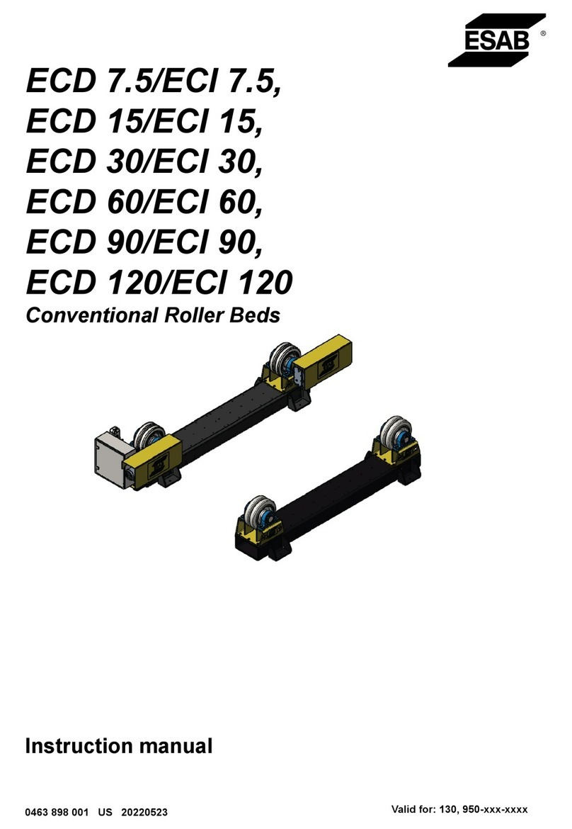
ESAB ESD 7.5 User manual

ESD7.5/ESI7.5, ESD15/ESI15,
ESD30/ESI30, ESD60/ESI60,
ESD90/ESI90,
ESD120/ESI120
Self-aligning Roller Beds
Instruction manual
0463 751 001 GB 20230428 Valid for: 015-xxx-xxxx, LX130-xxxx-xxxx


TABLE OF CONTENTS
0463 751 001 -3- © ESAB AB 2023
1 SAFETY ...................................................................................................................................... 5
1.1 Meaning of symbols.................................................................................................... 5
1.2 Non-compliant operation ............................................................................................ 5
1.3 Safety precautions ...................................................................................................... 5
2 INTRODUCTION......................................................................................................................... 8
2.1 Equipment.................................................................................................................... 8
2.2 Purpose and function of roller beds.......................................................................... 8
2.3 Terminology used in this manual............................................................................... 8
3 TECHNICAL DATA ..................................................................................................................... 9
3.1 ESD/ESI7.5 .................................................................................................................. 9
3.1.1 Drive unit, ESD7.5............................................................................................. 9
3.1.2 Idler unit, ESI7.5................................................................................................ 10
3.2 ESD/ESI 15 ................................................................................................................... 11
3.2.1 Drive unit, ESD 15.............................................................................................. 11
3.2.2 Idler unit, ESI 15................................................................................................. 12
3.3 ESD/ESI 30 ................................................................................................................... 13
3.3.1 Drive unit, ESD 30.............................................................................................. 13
3.3.2 Idler unit, ESI 30................................................................................................. 14
3.4 ESD/ESI 60 ................................................................................................................... 15
3.4.1 Drive unit, ESD 60.............................................................................................. 15
3.4.2 Idler unit, ESI 60................................................................................................. 16
3.5 ESD/ESI 90 ................................................................................................................... 17
3.5.1 Drive unit, ESD 90.............................................................................................. 17
3.5.2 Idler unit, ESI 90................................................................................................. 18
3.6 ESD/ESI 120 ................................................................................................................. 19
3.6.1 Drive unit, ESD 120............................................................................................ 19
3.6.2 Idler unit, ESI 120............................................................................................... 20
4 INSTALLATION........................................................................................................................... 21
4.1 Location........................................................................................................................ 21
4.2 Lifting instructions ...................................................................................................... 21
4.3 Adjusting the wheel stands ........................................................................................ 22
4.4 Adjusting the included angle ..................................................................................... 23
4.5 Installation procedure ................................................................................................. 24
4.6 PEK setup .................................................................................................................... 24
4.7 Roller bed configurations ........................................................................................... 26
5 OPERATION ............................................................................................................................... 27
5.1 Roller bed details ........................................................................................................ 27
5.2 Control panel ............................................................................................................... 27
5.3 Wireless remote - control pendant ............................................................................ 28
5.4 Switch the mains power on ........................................................................................ 29
5.5 Operating the roller beds............................................................................................ 30
5.6 Operation safety .......................................................................................................... 30
5.7 Welding......................................................................................................................... 31
5.8 Stopping the roller beds ............................................................................................. 31
6 MAINTENANCE.......................................................................................................................... 32
TABLE OF CONTENTS
0463 751 001 -4- © ESAB AB 2023
6.1 General ......................................................................................................................... 32
6.2 Storage ......................................................................................................................... 32
6.3 Repair and maintenance............................................................................................. 32
6.4 Cleaning ....................................................................................................................... 33
6.5 Breakdowns ................................................................................................................. 33
6.6 Gearmotors .................................................................................................................. 33
6.6.1 Gearmotors inspection and maintenance........................................................... 33
6.6.2 Gearbox lubrication ............................................................................................ 33
6.7 Inverters ....................................................................................................................... 34
6.8 Bearings ....................................................................................................................... 34
6.9 PU wheels .................................................................................................................... 34
7 TROUBLESHOOTING ................................................................................................................ 36
8 ORDERING SPARE PARTS ....................................................................................................... 37
WIRING DIAGRAM................................................................................................................................ 38
ORDERING NUMBERS......................................................................................................................... 43
ACCESSORIES ..................................................................................................................................... 44
SPARE PARTS ...................................................................................................................................... 45
SPARE PARTS - ESD 7.5 Mechanical parts list - Drive section........................................................ 46
SPARE PARTS - ESI 7.5 Mechanical parts list - Idler section........................................................... 48
SPARE PARTS - ESD15 Mechanical parts list - Drive section......................................................... 49
SPARE PARTS - ESI15 Mechanical parts list - Idler section............................................................ 51
SPARE PARTS - ESD30 Mechanical parts list - Drive section......................................................... 52
SPARE PARTS - ESI30 Mechanical parts list - Idler section............................................................ 54
SPARE PARTS - ESD 60 Mechanical parts list - Drive section......................................................... 55
SPARE PARTS - ESI60 Mechanical parts list - Idler section............................................................ 57
SPARE PARTS - ESD90 Mechanical parts list - Drive section......................................................... 58
SPARE PARTS - ESI90 Mechanical parts list - Idler section............................................................ 60
SPARE PARTS - ESD120 Mechanical parts list - Drive section....................................................... 61
SPARE PARTS - ESI120 Mechanical parts list - Idler section.......................................................... 63
SPARE PARTS - Control cabinet......................................................................................................... 64
SPARE PARTS - Electrical parts - Control cabinet............................................................................ 66
SPARE PARTS - Wireless control system.......................................................................................... 67

1 SAFETY
0463 751 001 -5- © ESAB AB 2023
1 SAFETY
1.1 Meaning of symbols
As used throughout this manual: Means Attention! Be Alert!
DANGER!
Means immediate hazards which, if not avoided, will result in immediate, serious
personal injury or loss of life.
WARNING!
Means potential hazards which could result in personal injury or loss of life.
CAUTION!
Means hazards which could result in minor personal injury.
WARNING!
Before use, read and understand the instruction manual and
follow all labels, employer´s safety practices and Safety Data
Sheets (SDSs).
1.2 Non-compliant operation
CAUTION!
These roller beds are not suitable for the following:
• Any vessel which is heavier than the maximum weight limit of the roller beds.
• Any vessel that is larger/smaller than the maximum/minimum diameter that can be supported.
• If the roller beds have polyurethane or rubber tires Do not use on preheated vessels above 60
°C.
1.3 Safety precautions
Users of ESAB equipment have the ultimate responsibility for ensuring that anyone who works on or
near the equipment observes all the relevant safety precautions. Safety precautions must meet the
requirements that apply to this type of equipment. The following recommendations should be observed
in addition to the standard regulations that apply to the workplace.
All work must be carried out by trained personnel well-acquainted with the operation of the equipment.
Incorrect operation of the equipment may lead to hazardous situations which can result in injury to the
operator and damage to the equipment.

1 SAFETY
0463 751 001 -6- © ESAB AB 2023
1. Anyone who uses the equipment must be familiar with:
• its operation
• location of emergency stops
• its function
• relevant safety precautions
• welding and cutting or other applicable operation of the equipment
2. The operator must ensure that:
• no unauthorised person is stationed within the working area of the equipment when it is started up
• no-one is unprotected when the arc is struck or work is started with the equipment
3. The workplace must:
• be suitable for the purpose
• be free from drafts
4. Personal safety equipment:
• Always wear recommended personal safety equipment, such as safety glasses, flame-proof clothing,
safety gloves
• Do not wear loose-fitting items, such as scarves, bracelets, rings, etc., which could become trapped or
cause burns
5. General precautions:
• Make sure the return cable is connected securely
• Work on high voltage equipment may only be carried out by a qualified electrician
• Appropriate fire extinguishing equipment must be clearly marked and close at hand
• Lubrication and maintenance must not be carried out on the equipment during operation
WARNING!
Arc welding and cutting can be injurious to yourself and others. Take precautions when
welding and cutting.
ELECTRIC SHOCK - Can kill
• Do not touch live electrical parts or electrodes with bare skin, wet gloves or wet
clothing
• Insulate yourself from work and ground.
• Ensure your working position is safe
ELECTRIC AND MAGNETIC FIELDS - Can be dangerous to health
• Welders having pacemakers should consult their physician before welding. EMF may
interfere with some pacemakers.
• Exposure to EMF may have other health effects which are unknown.
• Welders should use the following procedures to minimize exposure to EMF:
○ Route the electrode and work cables together on the same side of your body. Secure
them with tape when possible. Do not place your body between the torch and work
cables. Never coil the torch or work cable around your body. Keep welding power
source and cables as far away from your body as possible.
○ Connect the work cable to the workpiece as close as possible to the area being
welded.
FUMES AND GASES - Can be dangerous to health
• Keep your head out of the fumes
• Use ventilation, extraction at the arc, or both, to take fumes and gases away from your
breathing zone and the general area
ARC RAYS - Can injure eyes and burn skin
• Protect your eyes and body. Use the correct welding screen and filter lens and wear
protective clothing
• Protect bystanders with suitable screens or curtains

1 SAFETY
0463 751 001 -7- © ESAB AB 2023
NOISE - Excessive noise can damage hearing
Protect your ears. Use earmuffs or other hearing protection.
MOVING PARTS - Can cause injuries
• Keep all doors, panels and covers closed and securely in place. Have only qualified
people remove covers for maintenance and troubleshooting as necessary. Reinstall
panels or covers and close doors when service is finished and before starting the roller
beds.
• Stop the roller beds before installing or connecting unit.
• Keep hands, hair, loose clothing and tools away from moving parts.
FIRE HAZARD
• Sparks (spatter) can cause fire. Make sure therefore that there are no inflammable
materials nearby
HOT SURFACE - Parts can burn
• Do not touch parts bare handed.
• Allow cooling period before working on equipment.
• To handle hot parts, use proper tools and/or insulated welding gloves to prevent burns.
MALFUNCTION - Call for expert assistance in the event of malfunction.
PROTECT YOURSELF AND OTHERS!
CAUTION!
Class A equipment is not intended for use in residential locations
where the electrical power is provided by the public low-voltage
supply system. There may be potential difficulties in ensuring
electromagnetic compatibility of class A equipment in those
locations, due to conducted as well as radiated disturbances.
NOTE!
Dispose of electronic equipment at the recycling facility!
In observance of European Directive 2012/19/EC on Waste
Electrical and Electronic Equipment and its implementation in
accordance with national law, electrical and/or electronic
equipment that has reached the end of its life must be disposed of
at a recycling facility.
As the person responsible for the equipment, it is your
responsibility to obtain information on approved collection
stations.
For further information contact the nearest ESAB dealer.
ESAB has an assortment of welding accessories and personal protection equipment for
purchase. For ordering information contact your local ESAB dealer or visit us on our website.

2 INTRODUCTION
0463 751 001 -8- © ESAB AB 2023
2 INTRODUCTION
This Instruction manual describes the use and maintenance of the self-aligning roller beds, referred to
as roller beds in this document. Actions that must be carried out by the manufacturer are not included
in this manual.
This manual is part of the roller beds. Keep a copy of the manual with the roller beds and the original
in a safe place. If the roller beds are sold, supply the manual with it.
The pictures and diagrams used in this manual are for illustrative purposes only to help explain
instructions in the text. The equipment supplied may differ slightly.
2.1 Equipment
The roller bed drive is supplied with:
• Drive units
• Mounted control cabinet
• Wireless remote - control pendant
• Base frame
• Instruction manual
The roller bed idler is supplied with:
• Idler units
• Base frame
2.2 Purpose and function of roller beds
The roller beds are designed to aid the welding of cylindrical vessels.
By using the independent drive and idler units, vessels of varying lengths can be placed on the roller
beds supported on the roller bed wheels. The wheels can be adjusted on the base frame to
accommodate different vessel diameters.
2.3 Terminology used in this manual
Drive unit Roller bed section with powered wheels.
Idler unit Roller bed section with freewheeling wheels.
Roller bed set A set consists of one drive unit and one or more idler units.
Base frame The frame the drive or idler wheels are mounted on. These are pre-drilled
so that the wheel stands can be positioned for different vessel diameters.
Wheel stand The stand which houses the roller bed wheels. This is bolted down to the
baseframe.
Control panel Electrical control box mounted on the drive unit.
Wireless remote -
control pendant
A wireless operator hand control pendant.
Receiver The receiver that communicates with the wireless remote-control pendant.
Vessel Any component or device that is handled on the roller bed set.

3 TECHNICAL DATA
0463 751 001 -9- © ESAB AB 2023
3 TECHNICAL DATA
3.1 ESD/ESI7.5
3.1.1 Drive unit, ESD7.5
ESD 7.5
Max loading capacity 3750 kg (8269lb)
Turning capacity 11250kg (24806 lb)
Turning drive motor 2×0.25kW
Turning speed 150–1500mm/min (5.91–59.05in./min)
Workpiece diameter minimum Ø950mm (37.40in.) at 60° included angle
Workpiece diameter maximum Ø4000mm (157.48 in.) at 45° included angle
Mains supply 380–440V, 3phase, 50Hz
Mains fuse 16A
Roller type Polyurethane (90 °C / 92°A Shore)
Roller width / diameter 50 / 247 mm (1.97 / 9.72 in.)
Dimensions (L × W × H) 2775 × 776 × 808 mm (116.4 × 31.89 × 31.8 in.)
C-C 650, 910, 1170, 1430, 1690 mm
(25.59, 35.83, 46.06, 56.30, 66.54 in.)
Weight 550 kg (1213 lb)
Wireless remote - control
pendant
Wireless
Control voltage 24V
Operation temperature -15 to +40 °C (53.5 to 104 °F)
PEK settings, ESD 7.5
Gear 1 N1:N2 100:1

3 TECHNICAL DATA
0463 751 001 - 10 - © ESAB AB 2023
Gear 2 N1:N2 10:1
Gear 3 N1:N2 1:1
Wheel diameter 400mm (15.75 in.)
High manual speed 200cm/min (78.75 in./min)
Frequency ratio N1 50 Hz
Frequency ratio N2 50Hz
Max motor rpm 1592
3.1.2 Idler unit, ESI7.5
ESI 7.5
Max loading capacity 3750 kg (8269lb)
Roller type Polyurethane (90 °C / 92°A Shore)
Roller width / diameter 50 / 247 mm (1.97 / 9.72 in.)
Dimensions (L × W × H) 2200 × 500 × 721 mm (86.61 × 19.69 × 28.39 in.)
C-C 650, 910, 1170, 1430, 1690 mm
(25.59, 35.83, 46.06, 56.30, 66.54 in.)
Weight 400 kg (882 lb)

3 TECHNICAL DATA
0463 751 001 - 11 - © ESAB AB 2023
3.2 ESD/ESI 15
3.2.1 Drive unit, ESD 15
ESD15
Max loading capacity 7500 kg (16535lb)
Turning capacity 22500kg (49604 lb)
Turning drive motor 2×0.18kW
Turning speed 200-2000mm/min (5.51-78.74in./min)
Workpiece diameter minimum Ø1090mm (42.91in.) at 60° included angle
Workpiece diameter maximum Ø5400mm (212.60 in.) at 45° included angle
Mains supply 380-440V, 3phase, 50Hz
Mains fuse 16A
Roller type Polyurethane (90 °C / 92°A Shore)
Roller width / diameter 90 mm (3.54in.) / 300mm (11.81 in.)
Dimensions (L × W × H) 3365 × 801 × 883 mm (132.5 × 31.5 ×34.76in.)
C-C 760, 1140, 1520, 1900, 2280 mm
(29.92, 44.88, 59.84, 74.8, 89.76 in.)
Weight 700 kg (1544 lb)
Wireless remote - control
pendant
Wireless
Control voltage 24V
Operation temperature -15 to +40 °C
PEK settings, ESD15
Gear 1 N1:N2 100:1
Gear 2 N1:N2 10:1
Gear 3 N1:N2 1:1
Wheel diameter 400mm

3 TECHNICAL DATA
0463 751 001 - 12 - © ESAB AB 2023
High manual speed 200cm/min
Frequency ratio N1 50 Hz
Frequency ratio N2 50Hz
Max motor rpm 1592
3.2.2 Idler unit, ESI 15
ESI15
Max loading capacity 7500 kg (16535lb)
Roller type Polyurethane (90 °C / 92°A Shore)
Roller width / diameter 90 mm (3.54in.) / 300 mm (11.81 in.)
Dimensions (L × W × H) 2830 × 600 × 803 mm (111.42 × 23.62 × 31.61in.)
C-C 760, 1140, 1520, 1900, 2280 mm
(29.92, 44.88, 59.84, 74.8, 89.76in.)
Weight 600 kg (1323 lb)

3 TECHNICAL DATA
0463 751 001 - 13 - © ESAB AB 2023
3.3 ESD/ESI 30
3.3.1 Drive unit, ESD 30
ESD 30
Max loading capacity 15000 kg (33069lb)
Turning capacity 45000kg (99208 lb)
Turning drive motor 2×0.37kW
Turning speed 200-2000mm/min (5.51-78.74in./min)
Workpiece diameter minimum Ø1420mm (55.91 in.) at 60° included angle
Workpiece diameter maximum Ø4900mm (192.92 in.) at 45° included angle
Mains supply 380-440V, 3phase, 50Hz
Mains fuse 16A
Roller type Polyurethane (90 °C / 92°A Shore)
Roller width / diameter 90 mm (3.54in.) / 400mm (15.74in.)
Dimensions (L × W × H) 3358 × 817 × 915 mm (132.2 × 32.2 × 36.0 in.)
C-C 995, 1375, 1755, 2135 mm
(39.17, 54.12, 69.09, 84.06 in.)
Weight 1100 kg (2426 lb)
Wireless remote - control
pendant
Wireless
Control voltage 24V
Operation temperature -15 to +40 °C
PEK settings, ESD 30
Gear 1 N1:N2 100:1
Gear 2 N1:N2 10:1
Gear 3 N1:N2 1:1
Wheel diameter 400mm

3 TECHNICAL DATA
0463 751 001 - 14 - © ESAB AB 2023
High manual speed 200cm/min
Frequency ratio N1 50 Hz
Frequency ratio N2 50Hz
Max motor rpm 1592
3.3.2 Idler unit, ESI 30
ESI30
Max loading capacity 15000 kg (33069 lb)
Roller type Polyurethane (90 °C / 92°A Shore)
Roller width / diameter 90 mm (3.54in.) / 400mm (15.74in.)
Dimensions (L × W × H) 2848 × 700 × 859 mm (112.1 × 27.6 × 33.8in.)
C-C 995, 1375, 1755, 2135 mm
(39.17, 54.12, 69.09, 84.06 in.)
Weight 850 kg (1874 lb)

3 TECHNICAL DATA
0463 751 001 - 15 - © ESAB AB 2023
3.4 ESD/ESI 60
3.4.1 Drive unit, ESD 60
ESD60
Max loading capacity 30000 kg (66139lb)
Turning capacity 90000kg (198416 lb)
Turning drive motor 2×0.75kW
Turning speed 200-2000mm/min (5.51-78.74in./min)
Workpiece diameter minimum Ø1420mm (55.91in.) at 60° included angle
Workpiece diameter maximum Ø6300mm (248.03 in.) at 45° included angle
Mains supply 380-440V, 3 phase, 50Hz
Mains fuse 16A
Roller type Polyurethane (90 °C / 92°A Shore)
Roller width / diameter 2×90 mm (2×3.54 in.) / 400 mm (15.74 in.)
Dimensions (L × W × H) 4175 × 949 × 1158 mm (164.4 × 37.4 × 45.59in.)
C-C 995, 1415, 1835, 2255, 2675mm
(39.17, 55.71, 72,24, 88.78, 105.31in.)
Weight 2000 kg (4410 lb)
Wireless remote - control
pendant
Wireless
Control voltage 24V
Operation temperature -15 to +40 °C
PEK settings, ESD60
Gear 1 N1:N2 100:1
Gear 2 N1:N2 10:1
Gear 3 N1:N2 1:1
Wheel diameter 580mm

3 TECHNICAL DATA
0463 751 001 - 16 - © ESAB AB 2023
High manual speed 200cm/min
Frequency ratio N1 50 Hz
Frequency ratio N2 50Hz
Max motor rpm 1098
3.4.2 Idler unit, ESI 60
ESI60
Max loading capacity 30000 kg (66139lb)
Roller type Polyurethane (90 °C / 92°A Shore)
Roller width / diameter 2×90 mm (2×3.54 in.) / 400 mm (15.74 in.)
Dimensions (L × W × H) 3650 × 800 × 1039 mm (143.7 × 31.5 × 40.91in.)
C-C 995, 1415, 1835, 2255, 2675mm
(39.17, 55.71, 72,24, 88.78, 105.31in.)
Weight 1700 kg (3749 lb)

3 TECHNICAL DATA
0463 751 001 - 17 - © ESAB AB 2023
3.5 ESD/ESI 90
3.5.1 Drive unit, ESD 90
ESD90
Max loading capacity 45000 kg (66139lb)
Turning capacity 135000kg (297624 lb)
Turning drive motor 2×1.0kW
Turning speed 200-2000mm/min (5.51-78.74in./min)
Workpiece diameter minimum Ø2120 mm (83.46in.) at 60° included angle
Workpiece diameter maximum Ø6200mm (244.09 in.) at 45° included angle
Mains supply 380-440V, 3 phase, 50Hz
Mains fuse 16A
Roller type Polyurethane (90 °C / 92°A Shore)
Roller width / diameter 180 mm (7.09in.) / 580 mm (22.83in.)
Dimensions (L × W × H) 4167 × 1034 × 1142 mm (164.1 × 40.71 × 44.96 in.)
C-C 1470, 1890, 2310, 2730 mm
(57.87, 74.41, 90.94, 107.48 in.)
Weight 2550 kg (5623 lb)
Wireless remote - control
pendant
Wireless
Control voltage 24V
Operation temperature -15 to +40 °C
PEK settings, ESD90
Gear 1 N1:N2 100:1
Gear 2 N1:N2 10:1
Gear 3 N1:N2 1:1
Wheel diameter 580mm

3 TECHNICAL DATA
0463 751 001 - 18 - © ESAB AB 2023
High manual speed 200cm/min
Frequency ratio N1 50 Hz
Frequency ratio N2 50Hz
Max motor rpm 1098
3.5.2 Idler unit, ESI 90
ESI90
Max loading capacity 45000 kg (99208lb)
Roller type Polyurethane (90 °C / 92°A Shore)
Roller width / diameter 180 mm (7.09 in.) / 580 mm (22.83in.)
Dimensions (L × W × H) 3723 × 800 × 1126 mm (146.6 × 31.5 × 44.33in.)
C-C 1470, 1890, 2310, 2730 mm
(57.87, 74.41, 90.94, 107.48 in.)
Weight 2100 kg (4631 lb)

3 TECHNICAL DATA
0463 751 001 - 19 - © ESAB AB 2023
3.6 ESD/ESI 120
3.6.1 Drive unit, ESD 120
ESD120
Max loading capacity 60000 kg (132277 lb)
Turning capacity 180000kg (396832 lb)
Turning drive motor 2×1.5kW
Turning speed 200-2000mm/min (7.87-78.74in./min)
Workpiece diameter minimum Ø2120mm (83.46in.) at 60° included angle
Workpiece diameter maximum Ø6200 mm (244.09 in.) at 45° included angle
Mains supply 380-440V, 3 phase, 50Hz
Mains fuse 16A
Roller type Polyurethane (90 °C / 92°A Shore)
Roller width / diameter 180 mm (7.08in.) / 580 mm (22.83in.)
Dimensions (L × W × H) 4310 × 1108 × 1190 mm (169.7 × 43.62 × 46.85in.)
C-C 1470, 1890, 2310, 2730 mm
(57.87, 74.41, 90.94, 107.48 in.)
Weight 3000 kg (6615 lb)
Wireless remote - control
pendant
Wireless
Control voltage 24V
Operation temperature -15 to +40 °C
PEK settings, ESD120
Gear 1 N1:N2 100:1
Gear 2 N1:N2 10:1
Gear 3 N1:N2 1:1
Wheel diameter 580mm

3 TECHNICAL DATA
0463 751 001 - 20 - © ESAB AB 2023
High manual speed 200cm/min
Frequency ratio N1 50 Hz
Frequency ratio N2 50Hz
Max motor rpm 1098
3.6.2 Idler unit, ESI 120
ESI120
Max loading capacity 60000 kg (132277 lb)
Roller type Polyurethane (90 °C / 92°A Shore)
Roller width / diameter 180 mm (7.08in.) / 580 mm (22.83in.)
Dimensions (L × W × H) 3746 × 800 × 1142 mm (147.48 × 31.50 × 44.96in.)
C-C 1470, 1890, 2310, 2730 mm
(57.87, 74.41, 90.94, 107.48 in.)
Weight 2350 kg (5182 lb)
This manual suits for next models
11
Table of contents
Other ESAB Industrial Equipment manuals

ESAB
ESAB Aristo WeldCloud Mig U5000i User manual

ESAB
ESAB MechTrac 1730 User manual

ESAB
ESAB MechTrac 2500 User manual

ESAB
ESAB Tweco OCIM RB25T User manual

ESAB
ESAB OPC Flux recovery unit User manual

ESAB
ESAB KHM 2x400 PS User manual

ESAB
ESAB Cro User manual

ESAB
ESAB A6 TPC 75 User manual

ESAB
ESAB A6 Mastertrac A6TF User manual

ESAB
ESAB Warrior Feed 304 User manual