manuals.online logo
Brands
  1. Home
  2. •
  3. Brands
  4. •
  5. Festo
  6. •
  7. Industrial Equipment
  8. •
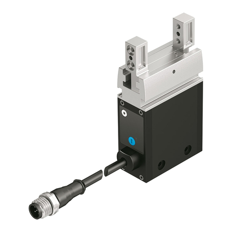
  9. Festo DHEF A-RA1 Series User manual

Festo DHEF A-RA1 Series User manual

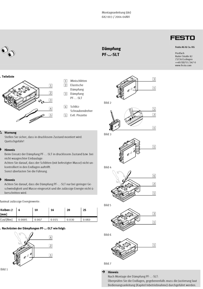
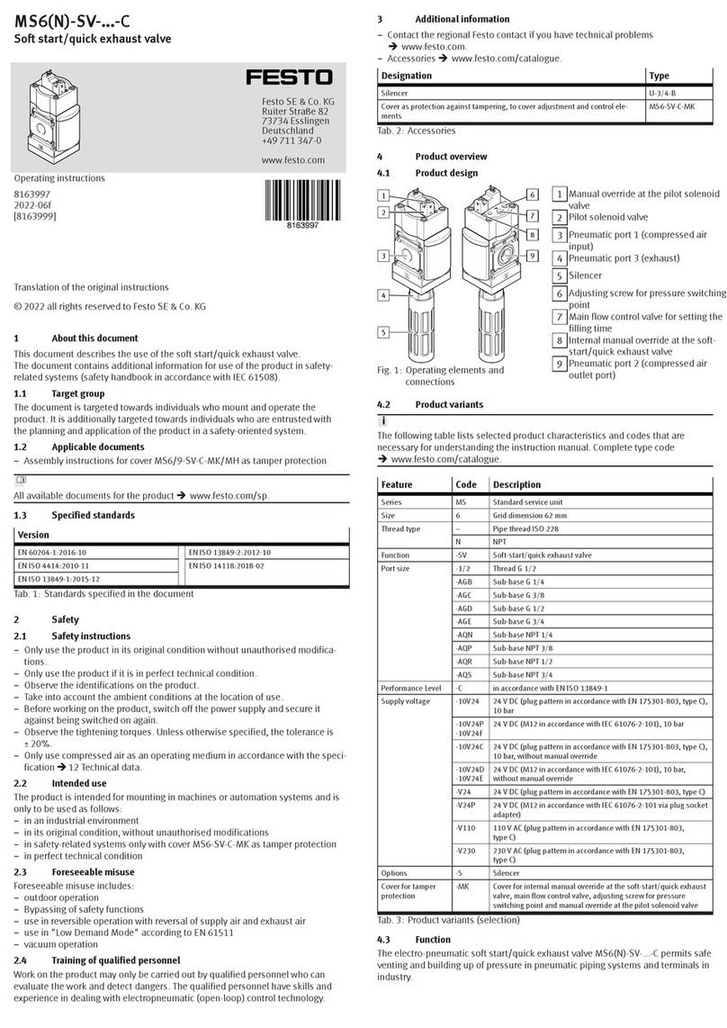
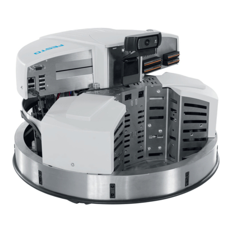
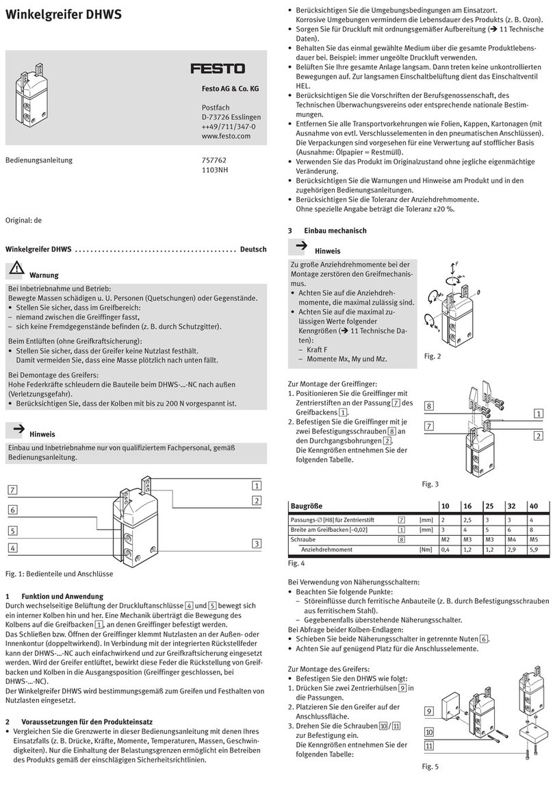
Translation of the original instructions
© 2020 all rights reserved to Festo SE & Co. KG
1 About this document
1.1 Applicable Documents
All available documents for the product èwww.festo.com/sp.
2 Safety
2.1 Safety Instructions
– Take into consideration the ambient conditions at the location of use.
– Only use the product in original status without unauthorised modifications.
– Observe labelling on the product.
– Store the product in a cool, dry, UV-protected and corrosion-protected envir-
onment. Ensure that storage times are kept to a minimum.
– Prior to mounting, installation and maintenance work: Switch off compressed
air supply and secure it from being switched back on.
– Observe tightening torques. Unless otherwise specified, the tolerance is
±20%.
2.2 Intended Use
The intended use of the gripper kit for robots is for integration into the UR soft-
ware and hardware connection for handling tasks of payloads.
Use the product only as follows:
– In perfect technical condition
– Within the limits of the product defined by the technical data
– In the industrial sector, in research laboratories, in assembly areas, in series
and special machines
– Permanently mounted
2.3 Training of Qualified Personnel
Installation, commissioning, maintenance and disassembly should only be con-
ducted by qualified personnel.
The specialized personnel must be familiar with the installation and operation of
electrical and pneumatic control systems.
3 Service
Contact your regional Festo contact person if you have technical questions
èwww.festo.com.
4 Design
1Robot flange
2Proximity sensor (2x)
3Socket head screw (4x)
4Adaptive shape gripper
5Velcro strap (2 m)
6Solenoid valve
7Silencer UC-M5
8Silencer UC-QS-4H
9USB memory stick
10 Proportional-pressure regulator
11 Connecting cable NEBU-
M8G4-R-5-LE4
12 Connecting cable NEBU-
M8G3-R-5-LE3 (2x)
13 Tubing PUN-6 (4m)
14 Tubing PUN-4 (2m)
15 Push-in fitting QSM-M5-6-I (5x)
16 Push-in fitting QSM-M5-4-I
Fig. 1 Parts overview
4.1 Functional Principle
"Grip" /"Release"- only adaptive shape gripper active
The "Grip" /"Release" functions are intended for operation of the adaptive shape
gripper - without movement of the robot arm.
– "Grip": the lower cylinder chamber is pressurised. The piston rod retracts.
– "Release": the upper cylinder chamber is pressurised while the lower one is
exhausted. The piston rod advances. Then both chambers are exhausted
(neutral position).
"SmartGrip" - Adaptive shape gripper and robot arm active
The process "SmartGrip" consists of four phases:
1. The robot arm moves in the Z-direction by the "Workpiece distance" value.
2. The workpiece is detected and the proximity sensor switches.
3. After detection of the workpiece, the robot arm moves the adaptive shape
gripper further in the Z-direction towards the workpiece. The piston rod
moves into the adaptive shape gripper and the cap slides around the work-
piece. The distance travelled by the piston rod is determined by the "Work-
piece grip height" parameter.
4. If it returned over the defined path "Workpiece grip height", the lower piston
chamber is pressurised and the piston rod is fully retracted. The adaptive
shape gripper does not move further down during the active retracting pro-
cess.
"SmartRelease" - Adaptive suction gripper and robot arm active
When the workpiece is released, the gripper moves upwards in the Z-direction
over the full stroke (66mm). At the same time, a pressure pulse is applied to the
upper piston chamber to advance the piston rod and release the object.
Precise placement
For precise placement, the gripped object should be positioned approx. 1 mm
above the support surface. If the object is completely enclosed by the cap, the
lower edge of the cap should be positioned accordingly.
5 Mechanical assembly
1. Screw push-in fittings aE (2x) into ports A and B on the adaptive shape grip-
per.
2. Screw push-in fitting aF into port C on the adaptive shape gripper.
3. Position adaptive shape gripper 4 on the robot flange 1 and tighten with
socket head screws 3 (4x). Tightening torque: 8 Nm
4. Screw push-in fittings aE (3x) into ports 1, 2 and 4 on the solenoid valve 6.
Tightening torque: 1.3 Nm
5. Screw silencer 7 (2x) into ports 3 and 5 on the solenoid valve 6.
6. Plug silencer 8 into port 3 on the proportional-pressure regulator aJ.
8123229
DHEF-...-A-RA1
Adaptive shape gripper
8123229
2020-01
[8123231]
Instructions| Assembly, Installation, Parameterisation
Festo SE & Co. KG
Ruiter Straße 82
73734 Esslingen
Germany
+49 711 347-0
www.festo.com
7. Mount solenoid valve 6 and proportional-pressure regulator aJ at a suitable
position on the robot foot.
6 Installation
6.1 Safety
Fig. 2 I/O settings
1. Switch the outputs "analog out[0]" and "analog out[1]" to [Voltage] and set
to 0 V.
2. Save setting: "Save"è"Save installation as..."
3. Overwrite the existing data with the selection "default.installation".
The "Analog Output" values must not be changed manually during operation -
they must be set to 0 V.
6.2 Pneumatic Installation
On-site requirements:
– Compressed air supply with a maximum pressure of 0.8 MPa (116 psi, 8 bar)
– 4 and 6 mm tubing lines
Tubing from Connection Tubing to Connection Tubing
Adaptive shape
gripper 4
O Solenoid valve 62 PUN-6
Adaptive shape
gripper 4
B Solenoid valve 64 PUN-6
Adaptive shape
gripper 4
C Proportional-pres-
sure regulator aJ
2 PUN-4
Solenoid valve 61 Compressed air
supply
Max. 0.8 MPa
(116 psi, 8 bar)
PUN-6
Proportional-pres-
sure regulator aJ
1 Compressed air
supply
Max. 0.65 MPa
(94 psi, 6.5 bar)
PUN-4
Tab. 1 Pneumatic Installation
6.3 Electrical Installation
WARNING!
Risk of injury due to electric shock
• For the electric power supply, use only PELV or SELV circuits that ensure a
reliable electric disconnection from the mains network.
1. Switch off power to the controller and safeguard it from being switched on
again unintentionally.
2. Slide proximity sensor 2 (2x) into the slots of the adaptive shape gripper 4
and fasten it. Position one proximity sensor on the flange side and one on the
cap side.
Laying cables and tubing
Fig. 3 Laying cables and tubing
The cables and tubing are attached to the outside of the robot arm using the sup-
plied Velcro straps.
Note the specified bending radii of the cables and tubing.
The freedom of movement of the robot must not be restricted by the cables and
tubing.
1. Cut the Velcro straps to length.
2. Lay cables and tubing along the robot arm.
3. Secure the cables and tubing with Velcro strips.
Connection for connecting cables to solenoid valve
1. Guide both connecting cables neatly into the control cabinet.
2. Connect the connecting cables according to the following table:
Insu-
lated
wire1)
Solenoid valve, connection 14
NEBU-M8G3-R-5-LE3
Solenoid valve, connection 12
NEBU-M8G3-R-5-LE3
BN Not assigned Not assigned
BU Digital Outputs 0V Digital Outputs 0V
BK Digital Outputs DO0 Digital Outputs DO1
1) wire colour when using connecting cables in accordance with accessories èwww.festo.com/cata-
logue
Tab. 2 Pin allocation for connecting cables to solenoid valve
Connection for connecting cable, proportional-pressure regulator
1. Guide both connecting cables neatly into the control cabinet.
2. Connect the connecting cables according to the following table:
Insu-
lated
wire1)
Proportional-pressure regulator
NEBU-M8G4-R-5-LE4
BN Digital Inputs 24V
WH Analog Outputs AO0
BU Digital Outputs 0V
BK Not assigned
1) wire colour when using connecting cables in accordance with accessories èwww.festo.com/cata-
logue
Tab. 3 Pin allocation of connecting cables for proportional-pressure regulator
Proximity sensor connection
1. Guide cables correctly into the control cabinet.
2. Connect cables in accordance with the following table:
Insu-
lated
wire1)
Proximity sensor,
flange side
Proximity sensor,
cap side
BN Digital Inputs 24V Digital Inputs 24V
BU Digital Outputs 0V Digital Outputs 0V
BK Digital Inputs DI0 Digital Inputs DI1
1) wire colour when using connecting cables in accordance with accessories èwww.festo.com/cata-
logue
Tab. 4 Pin allocation for cables to proximity sensors
6.4 Software installation
The software must be installed manually from the included USB memory stick.
The USB memory stick has the following data:
– URCap
– User documentation
System requirements for hardware and software:
• Robot UR3/UR5/UR10: from software version PolyScope CB 3.8.0
• Robot UR3e/UR5e/UR10e/UR16e: from software version PolyScope SW 5.0.0
Always use the current software version èwww.festo.com/sp
Older software versions may have a different appearance from this user docu-
mentation.
1. When the system is started, insert the USB memory stick into the control unit.
2. Press the "Menu" button at the top right of the header.
3. Select "Settings" menu item.
4. Select the "URCaps" button in the menu item "System".
5. Press the "+" button at the bottom left.
6. Select and open "FestoGripperDHEFURCap-XXXurcap".
X.X.X corresponds to the version number of the software e.g. 1.0.4
7. Press the "Restart" button at the bottom right.
ÄThe URCap is installed and can be used.
Fig. 4 Sample settings
6.5 Configuration of the software
Configuration of adaptive shape gripper
1Select gripper
2Activate/deactivate proximity
sensor
3Default values
4Activate/deactivate URCap
5Activate/deactivate URCap logging
Fig. 5 Configuration of adaptive shape gripper
1. Select grippers 1.
2. Observe default values 3. Adjustments are necessary if the cables of the
components were installed differently.
3. Adjust proximity sensors. The LED of a proximity sensor must be on at the cor-
responding end position.
Workpiece configuration
Fig. 6 Workpiece configuration
1. Selection of stored workpieces 1.
2. Create new workpieces in the list 2 or delete workpieces from the list 3.
3. Input workpiece weight 4.
4. Maximum distance between gripper and workpiece contact 5.
5. Passive path of the gripper 6.
6. Default values for speed and acceleration of the robot arm 7.
7. Pressurisation time for advancing the piston rod 8.
8. Deceleration of the pressurisation pulse after the start of the upward move-
ment 9.
9. The preset values can be tested by the "SmartGrip" and "SmartRelease"
functions. The user is guided through the function via dialogue.
Documentation
Information on installing the software and technical data of the adaptive shape
gripper.
Fig. 7 Documentation
Toolbar for manual control of the adaptive shape gripper
The functions of the adaptive shape gripper can be tested manually after pneu-
matic and electrical installation. A program sequence is not necessary.
Fig. 8 Toolbar for manual control of the adaptive shape gripper
Integrating "SmartGrip"/"Grip" and "SmartRelease"/"Release" program com-
mands
Fig. 9 Integrating program commands
1. Position 1 "SmartGrip"/"Grip" and "SmartRelease"/"Release" anywhere in
the program.
2. Workpiece selection 2.
3. The functions of the adaptive shape gripper can be manually 3 tested.
4. Gripping result successful/faulty 4
ÄOption for inserting additional program commands.
7 Clean product
• Clean the outside of the product with a soft cloth as required. Cleaning agents
include all non-abrasive media.
8 Fault clearance
Malfunction Possible cause Remedy
Frequent collision of
the robot
Exchange the "DO
grip" and "DO release"
allocation
Check setting and cabling
Object is not held after
the cap is retracted
Exchange the "DO
grip" and "DO release"
allocation
Check setting and cabling
Program sequence is
interrupted
Start and end condi-
tions of the commands
are not fulfilled
Check position of proximity sensor and readjust
Tab. 5 Fault clearance
9 Disposal
Dispose of the product and packaging at the end of its useful life through environ-
mentally friendly recycling in accordance with applicable regulations.
10 Technical data
Characteristic
Robot UR3/UR5/UR10: from software version Poly-
Scope CB 3.8.0
Robot software version
Robot UR3e/UR5e/UR10e/UR16e: from software ver-
sion PolyScope SW 5.0.0
Product weight (moving
mass)
[g] Adaptive shape gripper + proximity sensor (2x): 495
Tab. 6 Technical data, general

Other Festo Industrial Equipment manuals

Festo MS6-SP User manual

Festo

Festo MS6-SP User manual

Festo YSRWJ A Series User manual

Festo

Festo YSRWJ A Series User manual

Festo HGPLE User manual

Festo

Festo HGPLE User manual

Festo EXCH User manual

Festo

Festo EXCH User manual

Festo DFST Series User manual

Festo

Festo DFST Series User manual

Festo DHTG User manual

Festo

Festo DHTG User manual

Festo ELGC-BS User manual

Festo

Festo ELGC-BS User manual

Festo DNCKE S Series User manual

Festo

Festo DNCKE S Series User manual

Festo VABB-P3-1 User manual

Festo

Festo VABB-P3-1 User manual

Festo MPS 8046325 User manual

Festo

Festo MPS 8046325 User manual

Festo HGP A Series User manual

Festo

Festo HGP A Series User manual

Festo DADM-EP-G6 User manual

Festo

Festo DADM-EP-G6 User manual

Festo MPS 8046521 User manual

Festo

Festo MPS 8046521 User manual

Festo FSS-F-12 User manual

Festo

Festo FSS-F-12 User manual

Festo CPX-ST-1 User manual

Festo

Festo CPX-ST-1 User manual

Festo MPS 8038623 User manual

Festo

Festo MPS 8038623 User manual

Festo EPCS-BS User manual

Festo

Festo EPCS-BS User manual

Festo YXCL User manual

Festo

Festo YXCL User manual

Festo YXCF User manual

Festo

Festo YXCF User manual

Festo HGRT Series User manual

Festo

Festo HGRT Series User manual

Festo DG Series Parts list manual

Festo

Festo DG Series Parts list manual

Festo EMCS-ST User manual

Festo

Festo EMCS-ST User manual

Festo SLE-KF-A Series User manual

Festo

Festo SLE-KF-A Series User manual

Festo CRDNG Series Setup guide

Festo

Festo CRDNG Series Setup guide

Popular Industrial Equipment manuals by other brands

Hammerhead HG375 parts manual

Hammerhead

Hammerhead HG375 parts manual

BAC BCP2D Installation, Operating, Maintenance

BAC

BAC BCP2D Installation, Operating, Maintenance

Adtech UDB97 instruction manual

Adtech

Adtech UDB97 instruction manual

Robopac AETNAGROUP ROBOT S5 manual

Robopac

Robopac AETNAGROUP ROBOT S5 manual

Condair HP Series Installation and operation manual

Condair

Condair HP Series Installation and operation manual

Elesa DD51-E Instructions for use

Elesa

Elesa DD51-E Instructions for use

Zoeller MEDIUM X2 operating manual

Zoeller

Zoeller MEDIUM X2 operating manual

Bühler technologies GAS 222.30 Assembly, installation and operation instructions

Bühler technologies

Bühler technologies GAS 222.30 Assembly, installation and operation instructions

Blastrac 200VMB operating instructions

Blastrac

Blastrac 200VMB operating instructions

Fueltec BIO-VAC 270 product manual

Fueltec

Fueltec BIO-VAC 270 product manual

Bondtech DDG Ultimaker V2.0 Assembly and installation manual

Bondtech

Bondtech DDG Ultimaker V2.0 Assembly and installation manual

Tekelec EAGLE 5 Commands Error Recovery Manual

Tekelec

Tekelec EAGLE 5 Commands Error Recovery Manual

Morskate uni RTB M1 Assembly

Morskate

Morskate uni RTB M1 Assembly

BIRD TERMALINE 8860 Series Operation manual

BIRD

BIRD TERMALINE 8860 Series Operation manual

CBE PT642 user manual

CBE

CBE PT642 user manual

Teka LMD 501 SPA operating instructions

Teka

Teka LMD 501 SPA operating instructions

SCHUNK SLD Assembly and operating manual

SCHUNK

SCHUNK SLD Assembly and operating manual

Dantherm HRV 501 Service manual

Dantherm

Dantherm HRV 501 Service manual

manuals.online logo
manuals.online logoBrands
  • About & Mission
  • Contact us
  • Privacy Policy
  • Terms and Conditions

Copyright 2025 Manuals.Online. All Rights Reserved.