Idutex xTuner PT101 User manual

Automotive Circuit Tester
PT101
Users Manual
www. idutex. com

CATALOG
1. Safety Precautions and Warnings..................................................................1
2. Using the Test Tool.......................................................................................... 2
2.1 Appearance and Controls................................................................... 2
2.2 Specifications........................................................................................4
2.3 Product Included.................................................................................. 5
2.4 General Description............................................................................. 5
2.5 Power..................................................................................................... 6
2.6 Quick Self-Test..................................................................................... 6
2.7 Circuit Breaker......................................................................................7
2.8 Work mode............................................................................................ 8
3. Test Applications............................................................................................ 13
3.1 Voltage & Polarity Testing.................................................................13
3.2 Continuity Testing.............................................................................. 14
3.3 Signal Circuit Testing.........................................................................16
3.4 Activating Components in Your Hand............................................. 17
3.5 Testing Trailer Lights and Connections.......................................... 18
3.6 Activating Components in The Vehicle........................................... 19
3.7 Activating Components w/Ground...................................................20
3.8 Checking for Bad Ground Contacts................................................ 22
3.9 Following & Locating Short Circuits................................................ 22
3.10 Red/Blue Polarity LED.................................................................... 23
4. Test Tool Know-how...................................................................................... 24
5. Equipment Repair........................................................................................... 26
5.1 Product acceptance...........................................................................26
5.2 Product warranty................................................................................26
5.3 Product warranty process.................................................................26
5.4 Over-warranty product maintenance regulations......................... 27
6 Contact Us........................................................................................................ 27

Shenzhen IDUTEX Tech Co., Ltd
1
1. Safety Precautions and Warnings
To prevent personal injury or damage to vehicles and/or the test tool,
read this instruction manual first and observe the following safety
precautions at a minimum whenever working on a vehicle:
●Always perform automotive testing in a safe environment.
●Wear safety eye protection that meets ANSI standards.
●Keep clothing, hair, hands, tools, test equipment, etc. away from all
moving or hot engine parts.
●Operate the vehicle in a well ventilated work area: Exhaust gases are
poisonous.
●Put blocks in front of the drive wheels and never leave the vehicle
unattended while running tests.
●Use extreme caution when working around the ignition coil, distributor
cap, ignition wires and spark plugs. These components create hazardous
voltages when the engine is running.
●Put the transmission in PARK (for automatic transmission) or
NEUTRAL (for manual transmission) and make sure the parking brake is
engaged.
●Keep a fire extinguisher suitable for gasoline/chemical/ electrical fires
nearby.
●Don’t connect or disconnect any test equipment while the ignition is
on or the engine is running.
●Keep the tool dry, clean, free from oil/water or grease. Use a mild
detergent on a clean cloth to clean the outside of the test tool, when
necessary.
Shenzhen IDUTEX Tech Co., Ltd
2
ƔWhen the power switch in the tool is depressed battery current/voltage
is conducted directly to the tip which may cause sparks when contacting
ground or certain circuits. Therefore the tool should NOT be used around
flammables such as gasoline or its vapors. The spark of an energized tool
could ignite these vapors. Use the same caution as you would when using
an arc welde
2. Using the Test Tool
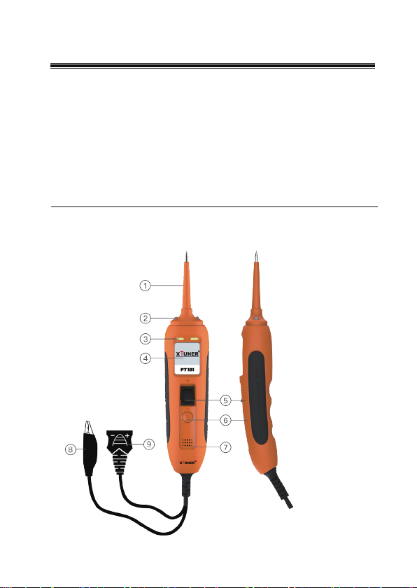
2.1 Appearance and Controls
Figure 1
r

Shenzhen IDUTEX Tech Co., Ltd
1
1. Safety Precautions and Warnings
To prevent personal injury or damage to vehicles and/or the test tool,
read this instruction manual first and observe the following safety
precautions at a minimum whenever working on a vehicle:
ƔAlways perform automotive testing in a safe environment.
ƔWear safety eye protection that meets ANSI standards.
ƔKeep clothing, hair, hands, tools, test equipment, etc. away from all
moving or hot engine parts.
ƔOperate the vehicle in a well ventilated work area: Exhaust gases are
poisonous.
ƔPut blocks in front of the drive wheels and never leave the vehicle
unattended while running tests.
ƔUse extreme caution when working around the ignition coil, distributor
cap, ignition wires and spark plugs. These components create hazardous
voltages when the engine is running.
ƔPut the transmission in PARK (for automatic transmission) or
NEUTRAL (for manual transmission) and make sure the parking brake is
engaged.
ƔKeep a fire extinguisher suitable for gasoline/chemical/ electrical fires
nearby.
ƔDon’t connect or disconnect any test equipment while the ignition is
on or the engine is running.
ƔKeep the tool dry, clean, free from oil/water or grease. Use a mild
detergent on a clean cloth to clean the outside of the test tool, when
necessary.

Shenzhen IDUTEX Tech Co., Ltd
4
2.2 Specifications
Display
TFT color display (160 x 128 PPI)
Dimensions
195 mm (7.68”) *50.5 mm (1.99”)*33mm
External Power 12.0 - 30.0V power provided via vehicle
battery. Recommended 12v power supply
Min Operating Voltage
8 VDC
Max Operating Voltage 12 VDC
Max Tip Voltage
40 Volts
Probe Tip Resistance
to Ground
1000 K Ohms
Computer Safe
0.1mA floating tip
Voltage Measurement
0 to 40 VDC / VAC
Voltage Resolution 0V -to 40V – 0.01V (10mV)
Glitch Capture
> 50 µS Min Pulse Width
Power Feed Test
< 3 mA
Resistance
Measurement
0 Ohms to 1M Ohms
Frequency
Measurement
40 Hz to 20KHz
Circuit Breaker 8 Amp Thermal – Auto Reset

Shenzhen IDUTEX Tech Co., Ltd
5
Breaker Trip Response
8 Amps = No Trip
8 Amps = 1 sec.
Short Circuit = 0.3 sec.
Operating Temperature -20°C (-4°F) to 50°C (122°F)
Storage Temperature
-40°C (-40°F) to 65°C (149°F)
2.3 Product Included
(1) User manual.
(2) Cigarette lighter adapter.
(3) Battery hookup clips.
(4) Probe tip.
(5) Extension cable.
(6) Rugged blow molded case.
2.4 General Description
Thank you for purchasing the Diagnostic Electronic Circuit
tester. The tool is the best electrical tester for reducing diagnostic time in all
6 to 30 volt vehicle electrical systems. After a simple hook-up of the tool to
the vehicle's battery, you can:
XTUNER PT101

Shenzhen IDUTEX Tech Co., Ltd
6
●determine at a glance if a circuit is positive, negative, or open without
having to reconnect clips from one battery pole to another.
●test for continuity with its built-in auxiliary ground lead.
●by depressing the power switch, conduct a positive or negative
battery current to the probe tip for testing the function of an electrical
component without the use of jumper wires.
●test for poor ground contacts instantly without performing voltage
drop tests. The tool is also short-circuit protected; its internal circuit
breaker will trip if it becomes overloaded.
●follow and locate short circuits without wasting fuses. The tool's long
cable allows you to test along the entire length of the vehicle without
constantly searching for suitable vehicle grounds.
2.5 Power
The tool is powered via the vehicle battery. Connect the RED battery
clamp to the POSITIVE terminal of the vehicle‟s battery, and the
BLACK clamp to the NEGATIVE terminal.
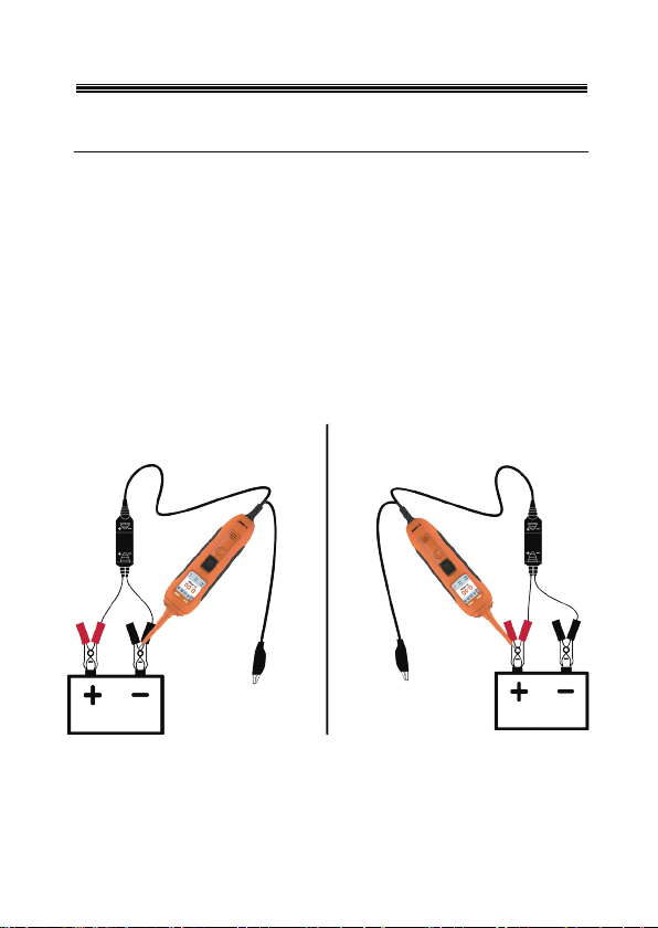
2.6 Quick Self-Test
Before you test a circuit or component, be sure your tool is in good order
by doing a quick self-test.
With the tool connected, perform a quick self-test. The power switch is a
momentary rocker switch located on the tool's body. Flanking the switch
are positive and negative markings.
Press the Power Switch forward to activate the tip with a positive
voltage. The Red LED should light and the LCD display will read the
battery voltage.

Shenzhen IDUTEX Tech Co., Ltd
7
Press the Power Switch rearward to activate the tip with a negative
voltage. The Blue LED should light and the LCD display will read the
“0.0V” (ground).
Your tool is working correctly and is now ready for use. (Figure 2)
Figure
IMPORTANT:
When powering-up components, you can
increase the life of power switch in the tool if you first press the
switch, then contact the tip to the component. The arcing will take
place at the tip instead of the contacts of the switch.
2.7 Circuit Breaker
The tool is short-circuit protected. Its internal circuit breaker will trip if
it becomes overloaded. The circuit breaker is a valuable test tool as well
as a safety measure to protect the tool from overload.
When circuit breaker tripped, All other functions of the tool are still active,
which means you can still probe a circuit and observe the voltage reading.
When the circuit breaker is tripped, the tool will NOT be able to conduct
2
Shenzhen IDUTEX Tech Co., Ltd
8
battery current to the tip even when the power switch is pressed.
Intentionally tripping the breaker and using the tool to probe can be
considered an added precaution against accidental pressing of the power
switch.
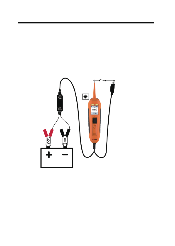
2.8 Work mode
There are four modes to diagnose the electrical systems, which can
be accessed by depressing the Mode Button and cycling through each
one.
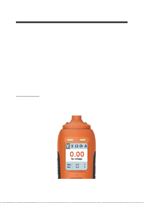
DC voltage
While the tool in this mode, contact the probe tip to a circuit, then the LCD
display will read the DC voltage with a resolution of 0.01 volt.(Figure 3)
Figure
3

Shenzhen IDUTEX Tech Co., Ltd
9
AC voltage
While the tool in this mode, contact the probe tip to a circuit, then the LCD
display will read the Max. voltage, the Min. voltage, frequency. ( Figure 4)
Figure
4
Shenzhen IDUTEX Tech Co., Ltd
10
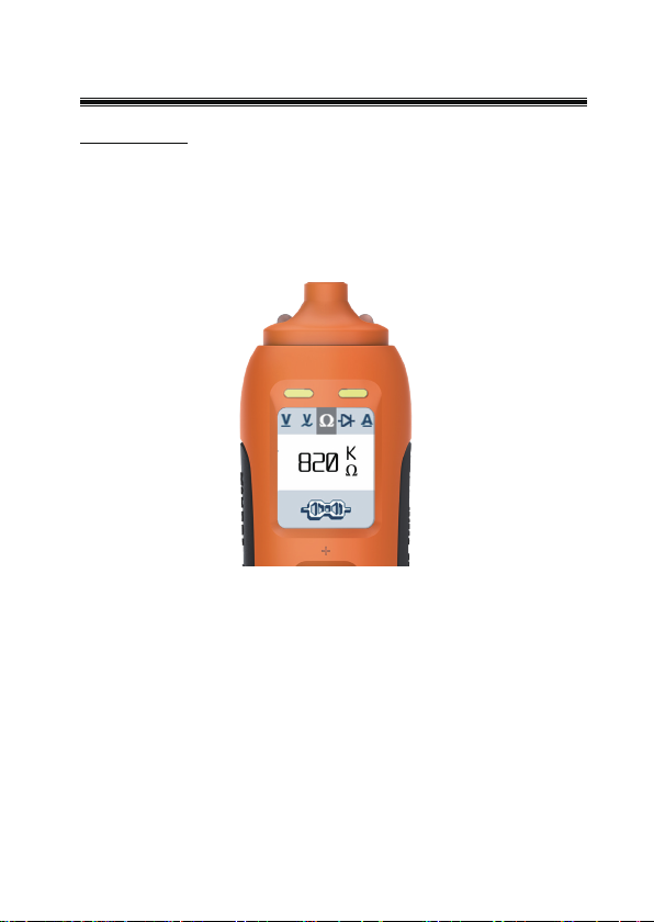
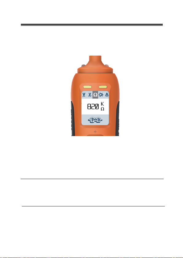
Resistance
While the tool in this mode, contact the probe tip to a circuit, then the
LCD display will read the resistance between the tip and auxiliary
ground lead. (Figure 5)
Figure 5

Shenzhen IDUTEX Tech Co., Ltd
11
Diode
While the tool in this mode, contact the probe tip to a circuit, then the
LCD display will read the diode voltage between the tip and auxiliary
ground lead. (Figure 6)
Figure 6
Shenzhen IDUTEX Tech Co., Ltd
12
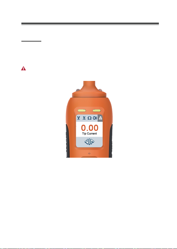
Current
While the tool in this mode, contact the probe tip to a circuit and press the
power switch up, then the LCD display will read the current with a
resolution of 0.1 A.( Figure 7)
Figure 7
Please do not test when power up more than 20V.
Shenzhen IDUTEX Tech Co., Ltd
13
3. Test Applications
3.1 Voltage & Polarity Testing
While the tool is in DC Voltage mode, contact the probe tip to a POSITIVE
circuit. The red LED will light and the LCD displays the voltage with a
resolution of 0.01V, a high pitched tone will sound.
If contact the probe tip to a NEGATIVE circuit, the blue LED will light and
the LCD displays the voltage with a resolution of 0.01V, a low pitched
tone will sound.
If contact the probe tip to an OPEN circuit, neither of the LED will
light.(Figure 8)
Figure 8
Shenzhen IDUTEX Tech Co., Ltd
14
3.2 Continuity Testing
While the tool is in Resistance mode, using the probe tip with chassis
ground or the auxiliary ground lead, continuity can be tested on wires
and components attached or disconnected from the vehicleெs electrical
system.
When the probe tip is contacting a good ground, the LCD will indicate “0
ȍ” and blue LED will be on, a low pitched tone will sound.喉Figure 9喊
Figure 9
Shenzhen IDUTEX Tech Co., Ltd
15
ƔIn other cases, the LCD only indicates the resistance value. (Figure 10)
Figure 10
ƔIf the resistance value is greater than 1Mȍ, the LCD will show “1.”.
NOTE: You can use the probe tip to pierce the plastic insulation on a
wire. This means that you can test the circuit without
disconnecting anything.
Shenzhen IDUTEX Tech Co., Ltd
16
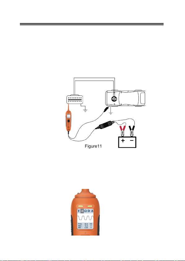
3.3 Signal Circuit Testing
Once you extract a DTC from the vehicle and realize that troubleshooting
begins with some kind of sensor circuit, there is a quick test you can
perform to verify the code. Testing your sensor is easy while using the tool.
For example, you suspect there is a problem with your M.A.P. sensor
circuit, then follow the procedure involved with testing this sensor:
ƔSet the tool in AC Voltage mode, using the probe tip with chassis
ground or the auxiliary ground lead.
ƔConnect vacuum pump to MAP sensor.
ƔContact the probe tip to the MAP sensor positive terminal and
observe the LCD readings which should be a sine wave in
normal condition.
ƔApply vacuum.
ƔRelease vacuum and observe the LCD readings.喉Figure 12喊
Figure11
If the LCD readings are abnormal, there is a problem with this sensor.
喉Figure 11喊
Figure 12

Shenzhen IDUTEX Tech Co., Ltd
17
3.4 Activating Components in Your Hand
While the tool is in DC Voltage mode, by using the probe tip in connection
with the auxiliary ground lead, components can be activated right in your
hand, thereby testing their functions.
Connect the auxiliary ground lead to the negative terminal or ground side
of the component being tested. Then contact the probe tip to the positive
terminal of the component, the blue LED should light, indicating continuity
through the component.
While keeping an eye on the blue LED, quickly press and release the
power switch forward. If the blue LED went out and the red LED came on,
you may proceed with further activation. Rock the power switch forward
and hold it down to provide power to your component. With the power
switch rocked forward, power will flow from the positive lead on the battery
into the probe tip, through the tip into the componentெs positive terminal,
into the component and out of the component, through the auxiliary
ground lead and back into the tool, and back to the vehicleெs batteryெs
ground. (Figure 13)
Figure 13
Contact the tip to the
p
ositive terminal of the
b
ulb
C
onnect the negative
auxiliary clip
Press the power switch
forward to active the
bulb

Shenzhen IDUTEX Tech Co., Ltd
18
If the circuit breaker tripped, the tool has been overloaded. This
could happen for the following reasons:
ƔThe contact you are probing is a direct ground or negative voltage.
ƔThe component you are testing is short-circuited.
ƔThe component is a very high current component (i.e., starter motor).
If the circuit breaker is tripped, reset it by waiting for it to cool down
(15 sec.) and then Reboot the device.
3.5 Testing Trailer Lights and Connections
While the tool in DC Voltage mode, clip the auxiliary ground lead to the
trailer ground, probe the contacts at the jack and then apply voltage to the
probe tip. This lets you check the function and orientation of the connector
and trailer lights. (Figure 14)
Figure 14
Table of contents


