DataTrak Operation
8313840N
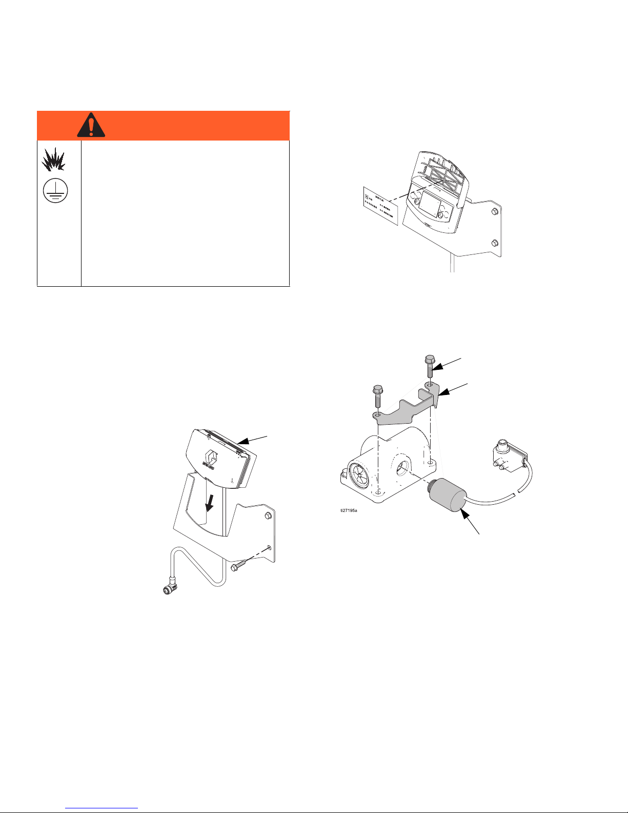
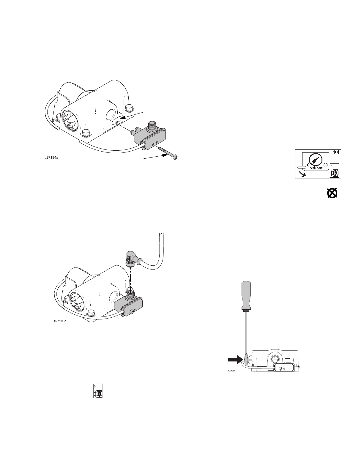
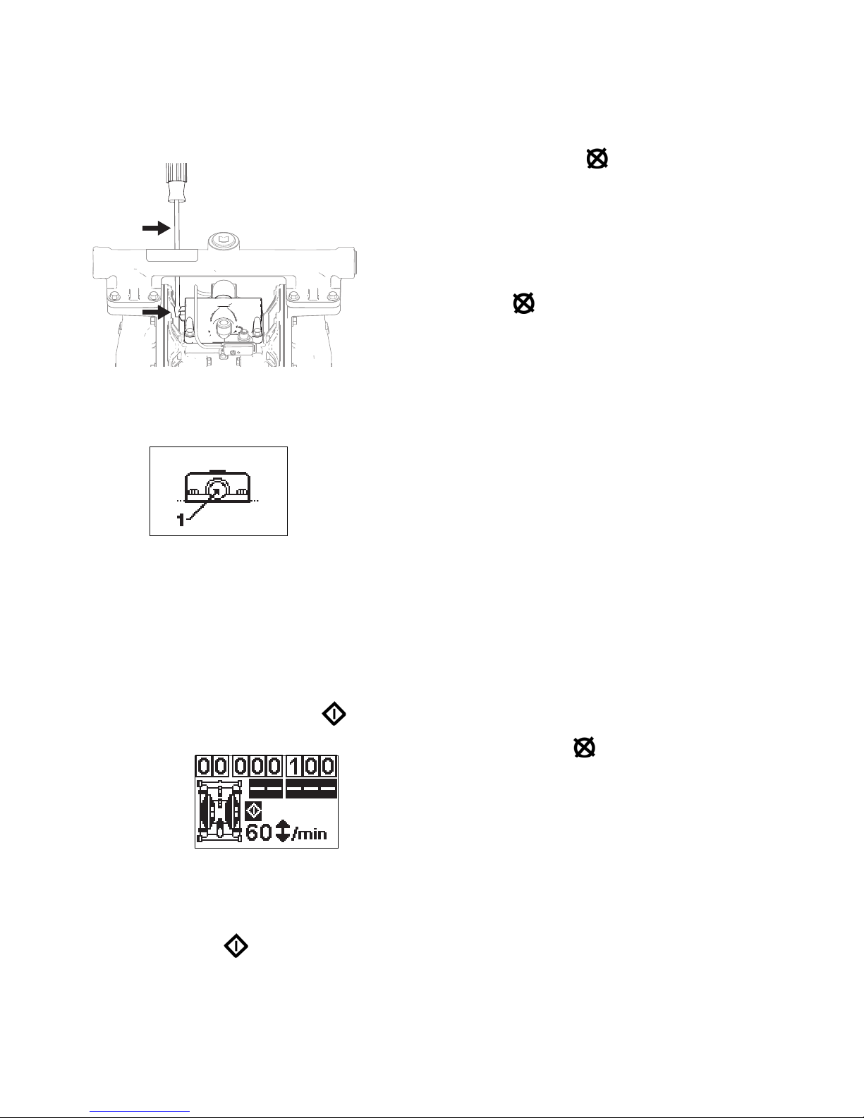
NOTE: If the DataTrak does not reset, use a screwdriver
to push the solenoid release button on the side of the air
valve.
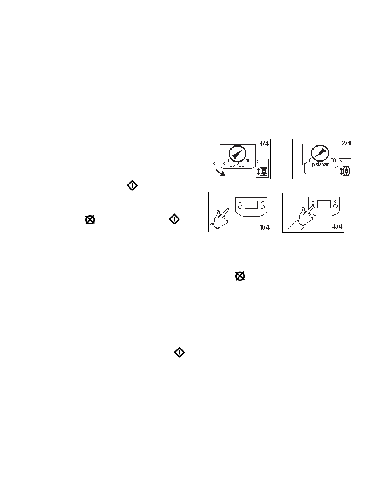
5. If the solenoid doesn’t actuate:
a. Close the master air valve to stop the pump.
The display will show the Service Component 1
screen.
b. See Table 1, Diagnostic Codes, on page 10.
NOTE: To disable runaway monitoring, go to setup
mode and set runaway value to 0 (zero). See Fig. 1.
Prime/Flush
1. See Fig. 1. To enter Prime/Flush mode, press any
key to wake up the display, then press . The
Prime/Flush symbol will appear in the display and
the LED will flash .
2. While in Prime/Flush mode, runaway protection is
disabled and the batch totalizer (BT) will not count.
3. To exit Prime/Flush mode, press any key to wake up
the display, then press . The Prime/Flush sym-
bol will disappear from the display and the LED will
stop flashing.
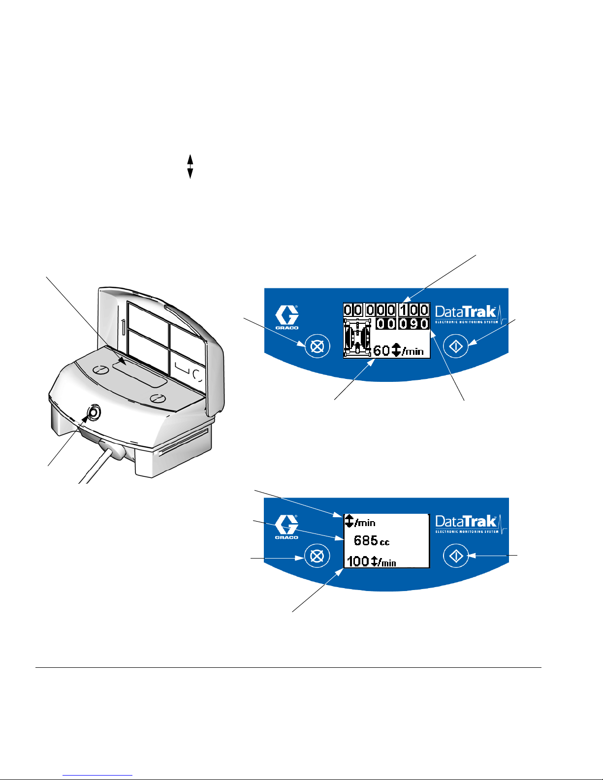
Counter/Totalizer
To reset the totalizer, press any key to wake up the dis-
play, then press and hold for 3 seconds.
• If AC is set to gallons or ounces, BT and GT dis-
play gallons.
• If AC is set to liters or cc, BT and GT display
liters.
• If AC is set to cycles, BT and GT display cycles.
NOTE: Press to toggle between flow rate units and
cycles. A letter under the BT display indicates that both
BT and GT are displaying gallons (g) or liters (l). No let-
ter means both BT and GT are displaying cycles.
Display
See Fig. 1. The display (AE) will turn off after 1 minute of
inactivity in Run mode or 3 minutes in Setup mode.
Press any key to wake up the display.
NOTE: DataTrak will continue to count cycles when dis-
play is off.
NOTE: The display (AE) may turn off if a high-level static
discharge is applied to the DataTrak. Press any key to
wake up the display.
Diagnostics
DataTrak can diagnose several problems with the pump.
When the monitor detects a problem, the LED (AD, Fig.
1) will flash and a diagnostic code will appear on the dis-
play. See Table 1, page 10.
To acknowledge the diagnosis and return to the normal
operating screen, press once to wake up the display,
and once more to clear the diagnostic code screen.