IEC G Y Series Instruction manual

•
Indoor Environment
and Air Quality
•
Design Flexibility
•
Performance
•
EnergyEfciency
•
Serviceability
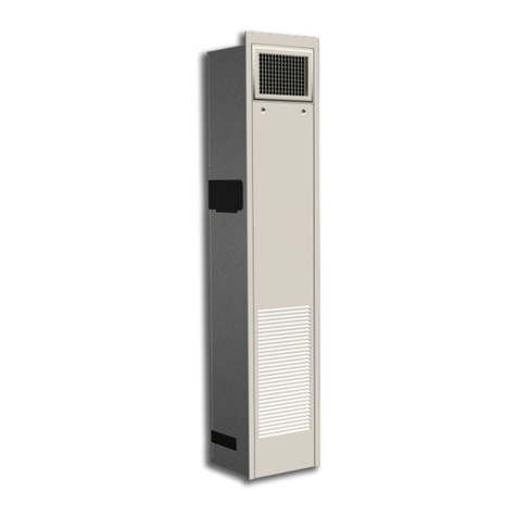
Cabinet Heater G*Y/D*Y Series
INSTALLATION, OPERATION, & MAINTENANCE MANUAL
Vertical & Horizontal
- Verticaloororwallmountedforconcealedorexposedapplications
- Horizontalceilingforexposedorpartiallyexposedapplications
- Hotwatercoils,steamcoils,orelectricheatonlyoptions
- Optionalcolors,valvepackages,controls,andunitcongurations
- NominalCFMrangeof200to1,200CFM
DBY
GXY

Cabinet Heater G*Y/D*Y Series
INSTALLATION, OPERATION, & MAINTENANCE MANUAL
2
Itistheresponsibilityoftheendusertoproperlycharacterizeand
disposeofallwastematerialsaccordingtoapplicableregulatory
and legal entities. Where reasonable, safe, and compliant with
localregulatoryandlegalrequirements,IECencouragesrecycling
materialswhendisposingofitsproducts.
InternationalEnvironmentalCorporation(IEC)workscontinually
toimproveitsproducts.Asaresult,thedesignandspecications
ofeachproductmaybechangedwithoutnoticeandmaynotbe
asdescribedherein.PleasecontactIECforinformationregarding
currentdesignandproductspecications.Statementsandother
informationcontainedhereinarenotexpresswarrantiesanddonot
formthebasisofanybargainbetweenthepartiesbutaremerely
IEC’sopinionorcommendation ofitsproducts. Manufacturer’s
standardlimitedwarrantyapplies.

Cabinet Heater G*Y/D*Y Series
INSTALLATION, OPERATION, & MAINTENANCE MANUAL
3
SECTION THREE — Controls Operation
18
Board Components and Specications
20 Board Function and Diagnostics
25 LED Functions and Outcomes
(sequence of operations)
26 Wiring Diagrams
SECTION FOUR — Normal Operation
and Maintenance
28 General
28 Motor/Blower Assembly
28 Bipolar Ionizer Brush Cleaning
29 Coil
29 Electric Heater Assembly
29 Electrical Wiring and Controls
30 Valves and Piping
30 Filters, Throwaway
30 Filters, Permanent
31 Replacement Parts
SECTION FIVE — Equipment Start-Up
32 Check List - IMPORTANT
33 Terms and Conditions
SECTION ONE — Installation
4 Preface
4 Unpacking and Inspection
5 Prepare Jobsite and Units
5Handling and Installation
6Unit Clearance and Service Access
8Vertical Series Unit Installation
9Cabinet Front Panel Installation
and Removal
9Decorative Wall Panels
Installation (GHY)
11 Optional Trim Kit Installation
11 Horizontal Series Unit Installation
12 Hydronic Heating Connections
13 Electrical Connections
15 Ductwork Connections
16 Final Preparations
SECTION TWO — Start-Up
17 General Start Up
17 Hydronic Heating System
17 Air System Balancing
18
Water Treatment
18
Water System Balancing
Table of Contents

Cabinet Heater G*Y/D*Y Series
INSTALLATION, OPERATION, & MAINTENANCE MANUAL
4
SECTION ONE — Installation
Preface
InternationalEnvironmentalCorporationcabinetheater
unitsrepresentaprudentinvestmentofferingtrouble-
freeoperationandlongservicewithproperinstallation,
operation,andregularmaintenance.Yourequipmentis
initiallyprotectedunderthemanufacturer’sstandard
warranty;however,thiswarrantyisprovidedunder
theconditionthatthestepsoutlinedinthismanualfor
initialinspection,properinstallation,regularperiodic
maintenance,andeverydayoperationoftheequipment
befollowedindetail.Thismanualshouldbefullyreviewed
inadvancebeforeinitialinstallation,start-up,andany
maintenance.Shouldanyquestionsarise,pleasecontact
yourlocalSalesRepresentativeorthefactoryBEFORE
proceeding.
Theequipmentcoveredbythismanualisavailable
withavarietyofoptionsandaccessories.Consultthe
approvedunitsubmittals,orderacknowledgment,and
othermanualsforspecicdetailsonunitoptionsand
accessories.
Noattemptshouldbemadetohandle,install,orservice
anyunitwithoutfollowingsafepracticesregarding
mechanicalequipment.
Theequipmentmustalwaysbeproperlysupported.
Temporarysupportsusedduringinstallationorservice
mustbeadequatetoholdtheequipmentsecurely.
Allpowermustbedisconnectedbeforeanyinstallation
orserviceisattempted.Morethanonepowersourcemay
besuppliedtoaunit.Powertoremotemountedcontrol
devicesmaynotbesuppliedthroughtheunit.
Neverwearbulkyorloose-ttingclothingwhenworking
onanymechanicalequipment.Glovesshouldalways
bewornforprotectionagainstheatandotherpossible
injuries.Safetyglassesorgogglesshouldalwaysbe
worn,especiallywhendrilling,cutting,orworkingwith
chemicalssuchasrefrigerantsorlubricants.
Neverpressurizeanyequipmentbeyondspeciedtest
pressuresasshownonunitratingplate.Alwayspressure
testwithaninertuidorgassuchasclearwaterordry
nitrogentoavoidpossibledamageorinjuryintheeventof
aleakorcomponentfailureduringtesting.
Alwaysprotectadjacentammablematerialwhen
weldingorsoldering.Useasuitableheatshieldmaterialto
containsparksordropsofsolder.Haveareextinguisher
readilyavailable.
Allmechanicalandelectricalconnectionsshouldbemade
byauthorizedpersonnelinaccordancewithNationaland
localcodeswhereapplicable.Themanufacturerassumes
noresponsibilityforpersonalinjuryorpropertydamage
resultingfromimproperorunsafepracticesduring
thehandling,installation,service,oroperationofany
equipment.
Unpacking and Inspection
Allunitsarecarefullyinspectedatthefactorythroughout
themanufacturingprocessunderastrictdetailedquality
assuranceprogram.Allmajorcomponentsandsub-
assembliesarecarefullytestedforproperoperation
andveriedforfullcompliancewithfactorystandards.
Operationaltestingofsomecustomer-furnished
componentssuchascontrolvalvesandelectroniccontrol
itemsmaybeapossibleexception.
Eachunitiscarefullypackagedforshipmenttoavoid
damageduringnormaltransitandhandling.Equipment
shouldalwaysbestoredinadryandcoveredlocationand
intheproperorientationasmarkedonthecarton.
AllshipmentsaremadeF.O.B.factoryanditisthe
responsibilityofthereceivingpartytoinspectthe
equipmentuponarrival.Anyobviousdamagetothe
cartonand/oritscontentsshouldberecordedonthebillof
ladingandaclaimshouldbeledwiththefreightcarrier.
Afterdeterminingtheconditionofthecartonexterior,
carefullyremoveeachunitfromthecartonandinspect
forhiddendamage.Atthistime,checktomakesure
thatfactoryprovideditemssuchasvalvepackages
andactuators,switches,thermostats,driplips,etc.,are
accountedfor.Anyhiddendamageshouldberecorded
andimmediatelyreportedtothecarrierandaclaimled.
Intheeventaclaimforshippingdamageisled,theunit,

Cabinet Heater G*Y/D*Y Series
INSTALLATION, OPERATION, & MAINTENANCE MANUAL
5
SECTION ONE — Installation, Cont’d.
shippingcarton,andallpackingmustberetainedfor
physicalinspectionbythefreightcarrier.Allequipment
shouldbestoredinthefactoryshippingcartonwith
internalpackinginplaceuntilinstallation.
Atthetimeofreceipt,theequipmenttypeand
arrangementshouldbeveriedagainsttheorder
documents.Shouldanydiscrepancybefound,thelocal
IECFactoryRepresentativeshouldbenotiedimmediately
sothatproperactionmaybetaken.
NOTE: Should any questions arise concerning warranty
repairs, the factory must be notied BEFORE any
corrective action is taken.
Prepare Jobsite and Units
Tosavetimeandtoreducethepossibilityofcostlyerrors,
setupacompletesampleinstallationinatypicalroomat
thejobsite.Checkallthecriticaldimensionssuchaseld
piping,wiring,andductconnectiontoensuretheyagree
withjobrequirements.Refertojobdrawingsandproduct
dimensiondrawingsasrequired(SeeFigure1forsample
drawing).Instructalltradesintheirpartoftheinstallation.
Shouldanydiscrepanciesbediscovered,contactyourlocal
representativebeforecontinuingwithunitinstallations.
Foreachunit,conrmincomingandcontrolpower
requirementsmatchavailablepowersource.Refertounit
nameplateandwiringdiagram.
1. Checkalltagsonunittodetermineifshipping
screwsaretoberemoved.Removescrewsas
directed.
2. Rotatethefanwheelbyhandtoensurethatthe
fanisunrestrictedandcanrotatefreely.Check
forshippingdamageandfanobstructions.Adjust
blowerwheelasrequired.
3. Perform“DryFit”ofvalveassemblythatmaybe
shippedunattachedtounitcoilassembly.Should
anyquestionsariseontuppleasecontactyour
localrepresentativeimmediately.
Handling and Installation
Whileallequipmentisdesignedandfabricatedwith
sturdymaterials,andmaypresentaruggedappearance,
greatcaremustbetakentoassurethatnoforceor
pressurebeappliedtothecoil,pipingordrainstub-
outsduringhandling.Also,dependingontheoptions
andaccessories,someunitscouldcontaindelicate
componentsthatmaybedamagedbyimproperhandling.
Whereverpossible,allunitsshouldbemaintainedinan
uprightposition,andhandledbythechassis,plenum
sections,orascloseaspossibletothemounting-point
locations.Inthecaseofafullcabinetunit,theunitmust
obviouslybehandledbytheexteriorcasing.Thisis
acceptableprovidingtheunitisagainmaintainedinan
uprightposition,andnoforceisappliedthatmaydamage
internalcomponentsorpaintedsurfaces.
TheequipmentcoveredinthismanualIS NOTsuitable
foroutdoorinstallations.Theequipmentshouldneverbe
storedorinstalledwhereitmaybesubjectedtoahostile
environmentsuchasrain,snow,orextremetemperatures.
Before,during,andafterinstallation,specialcaremustbe
takentopreventforeignmaterialsuchaspaint,plaster,
anddrywalldustfrombeingdepositedinthedrainpan
oronthemotororblowerwheels.Failuretodosomay
haveseriousadverseeffectsonunitoperation,andin
thecaseofthemotorandblowerassembly,mayresult
inimmediateorprematurefailure.Allmanufacturer’s
warrantiesarevoidifforeignmaterialisallowedtobe
depositedinthedrainpanoronthemotororblower
wheelsofanyunit.Someunitsand/orjobconditions
mayrequiresomeformoftemporarycoveringduring
construction.

Cabinet Heater G*Y/D*Y Series
INSTALLATION, OPERATION, & MAINTENANCE MANUAL
6
SECTION ONE — Installation, Cont’d.
Unit Clearance and Service Access
Forspecicunitdimensions,refertoTechnicalCatalogCA-010submittaldrawingsforyourmodel.Provideadequate
clearancefortheremovalofthepanel,accesstocontrolsorreplacementofinternalserviceablecomponentsincluding
airlters.Allowclearancesaccordingtolocalandnationalcodes.
Serviceaccessisavailablefromthefrontonverticalunits.Cabinetandrecessedunitshaveremovablefrontpanelsto
allowaccesstotheunit.
HydronicHeatunitshaveeitherrightorlefthandpiping.Referencepipinglocationsbyfacingthefrontoftheunit
(airowdischargesfromthefront).Thecontrolpanelisalwaysontheendoppositethepiping.
SeeFigures1and2forrecommendedserviceandoperatingclearances.
Size GHY GXY/GSY
02 23-1/2(597) 41(1041)
03 27-1/2(699) 45(1143)
04 33-1/2(851) 51(1295)
06 43-1/2(1105) 61(1549)
08 45-1/2(1156) 63(1600)
10 59-1/2(1511) 77(1956)
12 67-1/2(1715) 85(2159)
Table 1. Vertical Floor (GHY and GXY/GSY)Figure 1. Vertical Concealed (GHY)
8in.fromange
bothsides
36in.
SeeTable1 24in.
36in.
Figure 2. Vertical Cabinet (GXY, GSY)
SeeTable1

Cabinet Heater G*Y/D*Y Series
INSTALLATION, OPERATION, & MAINTENANCE MANUAL
7
SECTION ONE — Installation, Cont’d.
Size DBY DXY
02 37(940) 38(965)
03 37(940) 42(1067)
04 43(1092) 48(1219)
06 55(1397) 53(1346)
08 55(1397) 60(1524)
10 77(1956) 74(1880)
12 77(1956) 83(2083)
Table 2. Horizontal Ceiling Coil Removal
Minimum Service Clearance Width
12-18in.
see table 2 28in.
28in.
Figure 4. DXY Unit Clearance
Service Access
Controls
Side
Piping
Side
12-18in.
28in.
28in.
see table 2
Controls
Side
Piping
Side
Figure 3. DBY Unit Clearance
and Service Access

Cabinet Heater G*Y/D*Y Series
INSTALLATION, OPERATION, & MAINTENANCE MANUAL
8
SECTION ONE — Installation, Cont'd.
Vertical Series Unit Installation
GHY, GXY, GSY
Verticalunitmodelsaredesignedtobeoormountedor
otherwisesupportedfrombelowandboltedtothewall
oroorstructurethroughthemountingholesprovided
inthechassis.Theseunitsmaybewallmountedonly
whenoriginallyorderedfromthefactoryforwall-mount
applications.
Thetypeofmountingdeviceisamatterofchoice;
however,themountingpointshallalwaysbethatprovided
inthechassisorcabinet.Fastenersandotherrequired
hardwaremustbeeld-supplied.Refertotheunitproduct
drawingsforholemountinglocationsandsizes.
Floor Mount
1. Selecttheunitlocation.Allowforadequatespace
forfreeaircirculation,serviceclearances,piping
andelectricalconnections,andanynecessary
ductwork.
2. Makesuretheoorisabletosupporttheweight
oftheunit.Seesubmittaldrawingsfornominal
unitweight.
3. Ensurewallbehindunitissmoothandplumb;
ifnecessary,installfurringstripsonwallswith
irregularsurfacesormullions.Furringstrips
mustbepositionedbehindmountingholesin
unit.Fasteners,furringstrips,andotherseals(if
required)mustbeeld-supplied.
4. Removeallwallandoormoldingsfrombehind
theunit.
5. Adjustoptionalunitlevelinglegssounitislevel.
Unitmustbelevelforproperoperation.
Wall Mount
Figure 5. Wall Mount Hanger Hole Locations – GHY
Figure 6. Wall Mount Hanger Hole Locations – GXY, GSY
Table 3. C dimension for Wall Mount Hanger Hole Locations
Unit Model C
02 23(584)
03 27(686)
04 33(838)
06 43(1092)
08 45(1143)
10 59(1499)
12 67(1702)
1. Preparewallopeningsforrecessedunits.
Referencesubmittaldrawingsforunitsize
dimensions.
2 Markthepositionofthehangerholesonthewall
accordingtothedimensionsprovidedinFigures5
or6.Aligntheholelocationsevenly.
3. Preparetheeld-providedinstallationhardware
beforesettingtheunitinplace.

Cabinet Heater G*Y/D*Y Series
INSTALLATION, OPERATION, & MAINTENANCE MANUAL
9
SECTION ONE — Installation, Cont'd.
4. ForCabinetUnits(GXY,GSY),removethefront
panelbeforeinstallation.
5. Mounttheunitonthehangerhardware.Testto
verifytheunitisproperlysupported.
6. Completepipingandwiringconnections,in
additiontoanynecessaryductworktotheunitas
instructedinthefollowingsections.Ensurethat
theauxiliarydrainpanisinpositionforcoildrain,
whenapplicable.
7. Reinstallthefrontpanel(GXY,GSYcabinetunits)
beforestart-up.
Cabinet Front Panel Installation and Removal
ForGXY,GSYunits,replacethefrontpanelbyaligning
thebottomtabsontheunitwiththerespectiveslotson
thepanelbottom.Alignthetopedgeoftheunitwiththe
panel.
Decorative Wall Panels Installation (GHY)
For Fully Recessed Units
GHYmodelsarefullyrecessedandbuiltintothewallof
theconditionedareas.Theycovertherecessopeningon
allsidesandareeasilyremovedforaccesstotheunit.
Atop,bottom,andsideframingstudsarerequiredto
properlysecurethewallpaneltodrywall.Reference
Figures8and10forinstalldiagramrequirements.Secure
theWallpanelFRAMEtotheframingstudswitheld
suppliedmountinghardware.
Oncetheframeissecuredtothewall,installthepaneland
securetotheframewiththefactoryprovidedquarter-turn
camlocks.
Table 4. Style W & Z Framed Wall Panel Dimensions
Nominal
CFM
Panel
Width (A)
Inches
(mm)
Frame Width
(B)
Inches (mm)
Wall Opening
Inches (mm)
Width Height
200 40”(1016) 41-3/4”(1061) 40-3/8”(1026) 30-1/4”(768)
300 40”(1016) 41-3/4”(1061) 40-3/8”(1026) 30-1/4”(768)
400 50”(1270) 51-3/4”(1315) 50-3/8”(1280) 30-1/4”(768)
500 50”(1270) 51-3/4”(1315) 50-3/8”(1280) 30-1/4”(768)
600 60”(1524) 61-3/4”(1569) 60-3/8”(1534) 30-1/4”(768)
800 62”(1575) 63-3/4”(1619) 62-3/8”(1585) 30-1/4”(768)
1000 76”(1930) 77-3/4”(1975) 76-3/8”(1940) 30-1/4”(768)
1200 84”(2134) 85-3/4”(2178) 84-3/8”(2143) 30-1/4”(768)
Figure 7. Style W Framed Wall Panel
Style W

Cabinet Heater G*Y/D*Y Series
INSTALLATION, OPERATION, & MAINTENANCE MANUAL
10
SECTION ONE — Installation, Cont'd.
Figure 8. Style W Framed Wall Panel Install Diagram
Figure 9. Style Z Framed Wall Panel
Style Z
Figure 10. Style Z Framed Wall Panel Install Diagram

Cabinet Heater G*Y/D*Y Series
INSTALLATION, OPERATION, & MAINTENANCE MANUAL
11
SECTION ONE — Installation, Cont'd.
Optional Trim Kit Installation
Anoptionaltrimkitcanbeappliedtopartiallyrecessthe
GXY,GSYunitsinthewall.Thetrimkitcanalsobeapplied
tocoverroughopeningtoeliminatetheneedfornish
worksuchascarpentry,drywall,painting,etc.
Referenceunitsubmittaldrawingsforunitsizes.Trimkits
have1"anges.
Thereare3mountingbrackets(twosides,onetop)
providedinthetrimkitforoormountunits.Thereare
4mountingbrackets(twosides,top,bottom)inthetrim
kitforwallmountunits.Therearenomountingholes
providedontheunitsothebracketscanbepositionedat
whateverdepthsisrequiredforrecess.Useselftapping
screwstosecurethebracketstotheunit.
Figure 11. Trim Kit Around Floor Mount Unit
Horizontal Series Unit Installation
DBY, DXY
Anchoringtheequipmentinplaceisaccomplishedby
usingthemountingpointsprovidedwith3/8”all-thread
rodandotherhardware(notsuppliedwithunit).The
unitmustbepositionedsothatthecoilorelectricheat
elementsareonaLEVELPLANE.
Othereld-furnishedmountingdevicessuchasrubber-
in-shearorspring-typevibrationisolatorsselectedbythe
contractororengineermaybesubstitutedforthefactory
grommetsandshouldbeusedwherefactorygrommets
arenotprovided.Refertothedevicemanufacturerfor
installationinstructions.
Itshouldbenotedthatunacceptablesystemoperating
characteristicsand/orperformancemayresultfrom
improperorinadequateunitstructuralsupport.Adequate
clearancemustbeprovidedforserviceandremovalofthe
equipmentandanyaccessorycomponents.
Table 5. Threaded Rod Recommendations
Model Rod Diameter Rod Qty
D*Y02,03,04,06,08,10,12 3/8” 4
*NOTE–Threadedrodsandhardwareareprovidedbyothers.
Figure 12. Channel Mount Suspension*
*NOTE–Figure12depictsDBY.Hangerrailsandhardwareareprovidedbyothers.
CabinetunitmodelsDBYandDXYmaybemountedusing
fourneoprenegrommetsprovidedinthefourhangerholes
inthecasetop.

Cabinet Heater G*Y/D*Y Series
INSTALLATION, OPERATION, & MAINTENANCE MANUAL
12
SECTION ONE — Installation, Cont'd.
Ifcoilandvalvepackageconnectionsaretobemade
witha“sweat”orsolderjoint,careshouldbetakento
assurethatnocomponentsinthevalvepackageare
subjectedtoahightemperaturewhichmaydamage
sealsorothermaterials.Manytwo-positionelectric
controlvalves,dependingonvalveoperation,are
providedwithamanualopeninglever.Thislever
shouldbeplacedinthe“open”positionduringall
solderingorbrazingoperations.
Ground-Jointsealpreparationforcopperunions
(recommendedbymanufacturer):
1. Makesurethegroundjointareaisfreeof
nicksandscratches.
2. Spraytheground-jointareawithsilicone
sprayforbeeswaxtoenhanceseating.
3. Recommendedtorquesforgroundjointseal:
½”(nominal)unions–35ft./lbs.(minimum)
¾”(nominal)unions–60ft./lbs.(minimum)
4. Makesurealignmentoflinedoesnotput
lateralstressontheground-jointseal.
5. Makesurethatexcesssolderdropletsdonot
reachtheground-jointarea.
Ifthevalvepackageconnectionatthecoilismadewith
aunion,thecoilsideoftheunionmustbeprevented
fromtwisting(“backedup”)duringtighteningto
preventdamagetothecoiltubing.Over-tightening
mustbeavoidedtopreventdistorting(“eggshaping”)
theunionsealsurfaceanddestroyingtheunion.
Thesupplyandreturnconnectionsaremarkedon
thecoilstub-outsandthevalvepackage,withan“S”
meaningsupplyorinletand“R”meaningreturnor
outletindicatingowdirectiontoandfromthecoil.
Redlettersmarkthehotwaterconnections.
1. ForDXYandDBYunits,factoryprovidestube
extensionstopenetratetherearofthefancoil
cabinet.Hotextensiontubesmustbeproperly
insulated.
Hydronic Heating Connections
Aftermountingtheunit,itisthenreadyforthevarious
serviceconnectionssuchaswaterandelectrical.Atthis
time,itshouldbeveriedthatthepropertypesofservices
areactuallyprovidedtotheunit.Onthoseunitsrequiring
hotwater,theproperlinesizeandwatertemperature
shouldbeavailabletotheunit.
CAUTION: Toxic residues and loose particles
resulting from manufacturing and eld piping
techniques such as joint compounds, soldering ux, and
metal shavings may be present in the unit and the
piping system. Special consideration must be given to
system cleanliness when connecting to solar, domestic
or potable water systems.
Submittalsandproductliteraturedetailingunitoperation,
controls,andconnectionsshouldbethoroughlyreviewed
BEFOREbeginningtheconnectionofthevariouscooling
and/orheatingmediumstotheunit.
1. Auxiliary Drain Pan
Anoptionalauxiliarydrainpanisavailableforcoil
draining.
Theauxiliarydrainpanisshippedloosefromthe
factoryandmustbeinstalleddirectlybelowthecoil
drain.
Theauxiliarydrainpanissituatedtotheinner-case
legbywayofeithersupportingtabsextendingfrom
thecaselegorbywayofslotsinthecaseleg.The
drainpipeoradraintrapisthenconnectedtothe
stub-outoffthebottomofthepan.Conrmthatthe
panissecureandpositionedforproperoperation.
2. Valve Package Install (when applicable)
NOTE: Always protect hot water valve bodies,
strainers, ball valves, and other ow control related
devices from heat caused by soldering or brazing
processes by wrapping these devices in cold or
damp rags.
Allaccessoryvalvepackagesshouldbeinstalledas
required,andallservicevalvesshouldbecheckedfor
properoperation.

Cabinet Heater G*Y/D*Y Series
INSTALLATION, OPERATION, & MAINTENANCE MANUAL
13
SECTION ONE — Installation, Cont'd.
Labeleachtubeextensionforpurpose,i.e:
"HS"forHeatingSupply,etc.Soldertube
extensionstothevalvepackage.
2. Removevalveactuatorstemporarilyduring
valveinstallation.Protectunitwiringfrom
damage.
3. Install valve package.
4. Torqueunionstightusingbackupwrenchto
preventdamagetocoiltubes.Alignexiting
tubestothecenterofthepipeopenings.
5. Ifdesired,applysplitbushingsorgrommets
(providedbyothers)tothepipesfor
mechanicalsupportandprotection.Donot
allowcoppertubetocontactsteelcabinet.
6. Nowisagoodtimetoleaktesttheunions
andttings,usingairpressureandsoap.The
coilairvent(s)maybeusedforthispurpose.
Figure 13. General valve package assembly. DXY unit shown.
Aftertheconnectionsarecompleted,thesystem
shouldthenbetestedforleaks.Sincesome
componentsarenotdesignedtoholdpressurewith
agas,hydronicsystemsshouldbetestedwithwater.
Pressuretestingshouldbecompletedpriortosheet
rockingorpainting.
CAUTION: All water coils must be protected
from freezing after initial lling with water. Even
if the system is drained, unit coils may still hold enough
water to cause damage when exposed to temperatures
below freezing.
Intheeventthatleakingordefectivecomponentsare
discovered,theSalesRepresentativemustbenotied
BEFOREanyrepairsareattempted.Allleaksshouldbe
repairedbeforeproceedingwiththeinstallation.
Aftersystemintegrityhasbeenestablished,insulatethe
pipinginaccordancewiththeprojectspecications.Thisis
theresponsibilityoftheinstallingorinsulationcontractor.
Electrical Connections
Theelectricalservicetotheunitshouldbecomparedto
theunitnameplatetoverifycompatibility.Therouting
andsizingofallpiping,andthetypeandsizingofall
wiringandotherelectricalcomponentssuchascircuit
breakers,disconnectswitches,etc.shouldbedetermined
bytheindividualjobrequirements.Verifytheelectrical
conductorsizeissuitableforthedistancetotheequipment
connectionandwillsupporttheequipmentelectricalload.
Allinstallationsshouldbemadeincompliancewithall
governingcodesandordinances.Compliancewithallcodes
istheresponsibilityoftheinstallingcontractor.
Theunitserialplateliststheunitelectricalcharacteristics
suchastherequiredsupplyvoltage,fanandheater
amperageandrequiredcircuitampacities.Theunitwiring
diagramshowsallunitandeldwiring.Sinceeachproject
isdifferentandeachunitonaprojectmaybedifferent,
theinstallermustbefamiliarwiththewiringdiagramand
serialplateontheunitBEFOREbeginninganywiring.
Allcomponentsfurnishedforeldinstallationbyeitherthe
factoryorthecontrolscontractorshouldbelocatedand
checkedforproperfunctionandcompatibility.Allinternal
componentsshouldbecheckedforshippingdamage,and
anylooseconnectionsshouldbetightenedtominimize
problemsduringstart-up.
Anydevicessuchasfanswitchesorthermostatsthat
havebeenfurnishedfromthefactoryforeldinstallation
mustbewiredinstrictaccordancewiththewiring
diagramthatappearsontheunit.Failuretodosocould
resultinpersonalinjuryordamagetocomponentsandwill
voidallmanufacturer’swarranties.

Cabinet Heater G*Y/D*Y Series
INSTALLATION, OPERATION, & MAINTENANCE MANUAL
14
SECTION ONE — Installation, Cont'd.
Thefanmotor(s)shouldneverbecontrolledbyanywiring
ordeviceotherthanthe3-speedswitchorthermostat/
switchcombinationwithoutfactoryauthorization.
Fanmotor(s)maybetemporarilywiredforuseduring
constructiononlywithpriorfactoryapprovalinstrict
accordancewiththeinstructionsissuedatthattime.
Alleldwiringshouldbedoneinaccordancewith
governingcodesandordinances.Anymodicationofthe
unitwiringwithoutfactoryauthorizationwillvoidallofthe
factorywarranties,andwillnullifyanyagencylistings.
Themanufacturerassumesnoresponsibilityforany
damagesand/orinjuriesresultingfromimpropereld
installationand/orwiring.
1. Afterplanningforandbringingincomingpower
totheunit,locatethecontrolboxandcoverplate
(incomingelectricalpowerwiringcompartment).
Figure 14. Control box with cover plate
Incoming Electrical Power
Wiring Compartment
2. Determineappropriateknockouttofeedincoming
powerwiringintobox.
3. Loosenscrewstorotatecoverplatetoaccess
wiring.
Figure 15. Loosened covered plate

Cabinet Heater G*Y/D*Y Series
INSTALLATION, OPERATION, & MAINTENANCE MANUAL
15
SECTION ONE — Installation, Cont'd.
4. Secureincomingpowerwiringwithproper
serviceentranceconnectorand/orappropriate
strainrelief.Usewirenutsconnectionsthatmeet
wiregaugerequirements.
5. Replacecoverplateandsecurescrews.
Figure 16. External unit-mount control box access
Figure 17. Unit-mounted control box access
*NOTE–ImagedepictscontrolboxmountedinDBYunit
Figure 18. Thermostat unit-mount
*NOTE–ImagebelowdepictscontrolboxwithVentureWi-FiThermostat
Ductwork Connections
Allductworkand/orsupplyandreturngrillesshould
beinstalledinaccordancewiththeprojectplansand
specications.Ifnotincludedontheunitorfurnishedfrom
thefactory,supplyandreturngrillesshouldbeprovidedas
recommendedintheproductcatalog.
Forunitswithnoreturn-airductwork,checklocalcode
requirementsforpossibleapplicationrestrictions.Allunits
mustbeinstalledinareasthatarenon-combustible.
Somemodelsaredesignedtobeconnectedtoductwork
withaMINIMUMamountofexternalstaticpressure.
Theseunitsmaybedamagedbyoperationwithout
theproperductworkconnected.Consulttheapproved
submittalsandtheproductcatalogforunitexternalstatic
pressurelimitations.
Unitsprovidedwithoutsideairforventilationshouldhave
someformoflow-temperatureprotectiontopreventcoil
freeze-up.
Flexibleductconnectionsshouldbeusedonallair
handlingequipmenttominimizevibrationtransmissions.
Allductworkandinsulationshouldbeinstalledtoallow
properaccesstoallcomponentsforserviceandrepair
suchaslters,motor/blowerassemblies,etc.

Cabinet Heater G*Y/D*Y Series
INSTALLATION, OPERATION, & MAINTENANCE MANUAL
16
SECTION ONE — Installation, Cont'd.
Themanufacturerassumesnoresponsibilityfor
undesirablesystemoperationduetoimproperdesign,
equipmentorcomponentselection,and/orinstallationof
baseunit,ductwork,grilles,andotherrelatedcomponents.
Final Preparations
1. Turnoffpowertotheunit(openunitelectrical
disconnect)andinstalllockouttagsonallpower
suppliestounit.
2. Installthermostatsandperformanyothernalwiring
asapplicable.Ensureallelectricalconnectionsare
tight.
3. Performanalvisualinspection.Allequipment,
plenums,ductwork,andpipingshouldbeinspected
toverifythatallsystemsarecompleteandproperly
installedandmounted,andthatnodebrisorforeign
articlessuchaspaperordrinkcansareleftintheunits
orotherareas.Cleandirt,dust,andotherconstruction
debrisfromunitinterior.Besuretocheckfanwheel
andhousingandclean,ifnecessary.
4. Rotatefanwheelbyhandtobesureitisfreeand
doesnotrubhousing.Checkthatwingnutssecuring
fanassemblytofandeckaretight.Adjustifnecessary.
5. Installlter.Ifeld-suppliedltersareused,besure
sizeisasspeciedinTable3.
6. Ensureallpanelsandltersareinstalledbefore
checkingfanoperation.Turnonpowertotheunit.
7. Checkthefanandmotoroperation.
8. Whenauxiliarydrainpanisincluded,verifydrainine
isproperlyandsecurelypositionedandthatthelineis
clear.Pourwaterintodraintocheckoperation.

Cabinet Heater G*Y/D*Y Series
INSTALLATION, OPERATION, & MAINTENANCE MANUAL
17
SECTION TWO
— Start-Up
General Start Up
Beforebeginninganystart-upoperation,thestart-up
personnelshouldfamiliarizethemselveswiththeunit,
optionsandaccessories,andcontrolsequenceto
understandthepropersystemoperation.Allpersonnel
shouldhaveagoodworkingknowledgeofgeneral
start-upproceduresandhavetheappropriatestart-up
andbalancingguidesavailableforconsultation.
Thebuildingmustbecompletelynishedincludingdoors,
windows,andinsulation.Allinternalwallsanddoors
shouldbeinplaceandinthenormalposition.Insome
casestheinteriordecorationsandfurnituremayinuence
overallsystemperformance.Theentirebuildingshould
beascompleteaspossiblebeforebeginninganysystem
balancing.
Theinitialstepinanystart-upoperationshouldbeanal
visualinspection.Allequipment,plenums,duct-work,and
pipingshouldbeinspectedtoverifythatallsystemsare
completeandproperlyinstalledandmounted,andthatno
debrisorforeignarticlessuchaspaperordrinkcansare
leftintheunitsorotherareas.
Eachunitshouldbecheckedfor:
1. freeblowerwheeloperation
2. loosewires
3. looseormissingaccesspanelsordoors
4. cleanlterofthepropersizeandtype
Exceptasrequiredduringstart-upandbalancingoperations,
nofancoilunitsshouldbeoperatedwithoutalltheproper
ductworkattached,supplyandreturngrillesinplace,andall
accessdoorsandpanelsinplaceandsecure.Failuretodo
socouldresultindamagetotheequipmentorbuildingand
furnishings,and/orvoidallmanufacturer’swarranties.
Hydronic Heating System
Priortothewatersystemstart-upandbalancing,thehot
watersystemsshouldbeushedtocleanoutdirtand
debriswhichmayhavecollectedinthepipingduring
construction.Duringthisprocedure,allunitservicevalves
mustbeintheclosedposition.Thispreventsforeign
matterfromenteringtheunitandcloggingthevalves
andmeteringdevices.Strainersshouldbeinstalledinthe
pipingmainstopreventthismaterialfromenteringthe
unitsduringnormaloperation.
Duringsystemlling,airventingfromtheunitis
accomplishedbytheuseofthestandard,manualairvent
tting,ortheoptional,automaticairventttinginstalled.
Toventtheairfromthecoil,depressthevalveuntiltheair
hasventedthecoil.Whenwaterbeginstoescapethrough
thevalve,releasethevalve.Automaticairventsmaybe
unscrewedoneturncounterclockwisetospeedinitial
venting,butshouldbescrewedinforautomaticventing
afterstart-upoperations.
CAUTION! The air vent provided on the unit is
not intended to replace the main system air vents
and may not release air trapped in other parts of the
system. Inspect the entire system for potential air traps
and vent those areas as required, independently. In
addition, some systems may require repeated venting over
a period of time to properly eliminate air from the system.
Air System Balancing
Allductworkmustbecompleteandconnected.Allgrilles,
lters,andaccessdoorsandpanelsmustbeproperly
installedtoestablishactualsystemoperatingconditions
BEFOREbeginningairbalancingoperations.
Eachindividualunitandtheattachedductworkisa
uniquesystemwithitsownoperatingcharacteristics.For
thisreason,airbalancingisnormallydonebybalance
specialistswhoarefamiliarwithallproceduresrequired
toproperlyestablishairdistributionandfan-system
operatingconditions.Theseproceduresshouldnotbe
attemptedbyunqualiedpersonnel.
Exposedunitswithoutductworkdonotrequireair
balancingotherthanselectingthedesiredfanspeed.
Afterpropersystemoperationisestablished,theactual
unitairdeliveryandtheactualfanmotoramperagedraw
foreachunitshouldberecordedinaconvenientplacefor
futurereference.

Cabinet Heater G*Y/D*Y Series
INSTALLATION, OPERATION, & MAINTENANCE MANUAL
18
Water Treatment
Properwatertreatmentisaspecializedindustry.IEC
recommendsconsultinganexpertinthiseldtoanalyze
thewaterforcompliancewiththewaterqualityparameters
listedbelow,andtospecifytheappropriatewatertreatment
regimen.Theexpertmayrecommendtypicaladditivessuch
asrustinhibitors,scalingpreventative,antimicrobialgrowth
agents,oralgaepreventatives.Antifreezesolutionsmay
alsobeusedtolowerthefreezingpoint.
IECwatercoiltubesandheadersareconstructedofpure
copper.Multiplebrassalloysmaybepresentinthevalve
package,dependingonunitconguration.Itistheuser’s
responsibilitytoensurethetubeandpipingmaterials
furnishedbyIEC,arecompatiblewiththetreatedwater.
Failure to provide proper water quality will void the fan
coil unit’s warranty.
Water Containing Required Concentration
Sulphate Lessthan200ppm
pH 7.0–8.5
Chlorides Lessthan200ppm
Nitrate Lessthan100ppm
Iron Lessthan4.5mg/l
Ammonia Lessthan2.0mg/l
Manganese Lessthan0.1mg/l
DissolvedSolids Lessthan1000mg/l
CaCO3Hardness 300-500ppm
CaCO3Alkalinity 300-500ppm
ParticulateQuantity Lessthan10ppm
ParticulateSize 800micronmax
SECTION TWO — Start-Up, Cont'd.
Water System Balancing
Acompleteknowledgeofthehydronicsystem,alongwith
itscomponentsandcontrols,isessentialtoproperwater
systembalancing.Thisprocedureshouldnotbeattempted
byunqualiedpersonnel.Thesystemmustbecomplete,
andallcomponentsmustbeinoperatingcondition
BEFOREbeginningwatersystembalancingoperations.
Eachhydronicsystemhasdifferentoperatingcharacteristics
dependingonthedevicesandcontrolsusedinthesystem.
Theactualbalancingtechniquemayvaryfromonesystem
toanother.
Afterthepropersystemoperationisestablished,the
appropriatesystemoperatingconditionssuchasvarious
watertemperaturesandowratesshouldberecordedin
aconvenientplaceforfuturereference.
Before,andduringwatersystembalancing,conditions
mayexistduetoincorrectsystempressureswhich
mayresultinnoticeablewaternoiseorundesiredvalve
operation.Aftertheentiresystemisbalanced,these
conditionswillnotexistonproperlydesignedsystems.
SECTION THREE – Controls Operation
Board Components and Specications
Beforepropercontroloperationcanbeveried,allother
systemsmustbeoperatingproperly.Thecorrectwaterand
airtemperaturesmustbepresentforthecontrolfunction
beingtested.Awiderangeofcontrols,electricaloptions
andaccessoriesmaybeusedwiththeequipmentcovered
inthismanual.Consulttheapprovedunitsubmittals,
orderacknowledgments,andotherliteraturefordetailed
informationregardingeachindividualunitanditscontrols.
Sincecontrolsandfeaturesmayvaryfromoneunitto
another,careshouldbetakentoidentifythecontrolsused
oneachunitandtheirpropercontrolsequence.Information
providedbycomponentmanufacturersregarding
installation,operation,andmaintenanceoftheirindividual
controlsisavailableuponrequest.

Cabinet Heater G*Y/D*Y Series
INSTALLATION, OPERATION, & MAINTENANCE MANUAL
19
SECTION THREE – Controls Operation
1CN1–24VCustomerInput(Thermostat)
2 CN2–Changeover/ReturnAirSensor
3CN3–RemoteShutdownInput
4CN4–CondensateOverowSwitch
5CN5–TwoStageCooling
6CN6–Actuator7Aquastat
7 CN7–Transformer
8 CN8–LineServiceVoltage
9 CN9–PSCMotorConnection
10 CN10–ECMConnection
11 ECMFanSpeedAdjustment
12 GroundConnection
13 LEDDiagnostics(forMultimeterDiagnostics)
85 Control Board (E025-71481108)
Changeover/Return Air Sensor (CN2)
Pluggable T-Stat Connector (CN1)Remote Shutdown Input (CN3)
Overow Switch (CN4)
Two-Stage
Cooling (CN5)
Actuator & Aquastat (CN6)
Transformer (CN7) Line Service Voltage (CN8)
PSC Motor Connection (CN9)
ECM Connection (CN10)
ECM Fan Speed
Adjustment
LED Indication(s)
1
2
4
3
5
6
7 8
9
10
11
13
12

Cabinet Heater G*Y/D*Y Series
INSTALLATION, OPERATION, & MAINTENANCE MANUAL
20
SECTION THREE – Controls Operation, Cont'd.
Board Function and Diagnostics
1. CN1 – 24V Customer Input (Thermostat)
Useproperwiregaugeandinsulationtypebasedonapplicationandlocalcoderequirements.
FordetailedIEC24Vthermostatcontrolwiringdiagrams,referencethermostatIOMs.
For Factory Installed IEC 24V Thermostat*
* DoesnotapplytoproportionalorLinevoltagethermostatcontrols.ThediagrambelowrepresentsafactoryinstalledIEC24Vthermostat.
Connection Function/Description
(+)10V Notused
(-)COM Groundcontrolpower
G3/HI FanHighSpeed
G2/MED FanMediumSpeed
G1/LOW FanLowSpeed
W1/HTG Heat
Y1/CLG Cool
W2/HT2 Heatstage2
Y2/CL2 Coolstage2
R/24V 24VControllerPower
COS Changeoversensor
RAS Roomairsensor
Figure 19. Thermostat wire harness connection
Figure 20. Mounted thermostat connection
*NOTE–ImagedepictsanIECunit-mountedVentureWi-FiThermostat.
This manual suits for next models
6
Table of contents
Other IEC Heater manuals
Popular Heater manuals by other brands

Stanley
Stanley ST-300A-120 User's manual & operating instructions
Opal
Opal ASB540 user manual
Hatco
Hatco POWERMITE PMG-100 Installation and operating manual

Claudgen
Claudgen HE7010 Additional Installation, Operation and Maintenance Instructions

Linea 2000
Linea 2000 Domo DO7315M Instruction booklet

Atlantic
Atlantic SFEG manual
