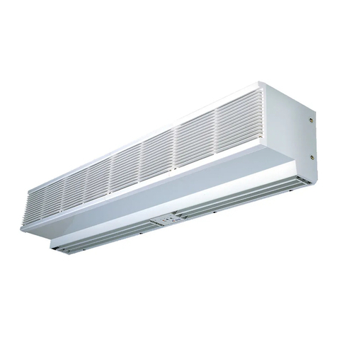
Gree FP ZD-K(E) Series User manual

USER MANUAL
[ FCU - FLOOR CEILING ]
FP-xxZD-K(E)
EN ORIGINAL INSTRUCTIONS, VER. 01 2019-11-18

IMPORTANT NOTE:
Read this manual carefully before installing or operating your new air conditioning unit.
Make sure to save this manual for future reference.

To Users
Thank you for selecting Gree’s product. Please read this instruction manual carefully before installing
and using the product, so as to master and correctly use the product. In order to guide you to correctly
install and use our product and achieve expected operating eect, we hereby instruct as below:
(1) This equipment should be installed, operated or maintained by the qualied servicemen who have had
specic training. During operation, all safety issues covered in the labels, User’s Manual and other
literature should be followed strictly. This equipment is not intended for use by persons (including
children) with reduced physical, sensory or mental capabilities, or lack of experience and knowledge,
unless they have been given supervision or instruction concerning use of the appliance by a person
responsible for their safety. Children should be supervised to ensure that they do not play with the
appliance.
(2) This product has gone through strict inspection and operational test before leaving the factory. In order
to avoid damage due to improper disassembly and inspection, which may impact the normal operation
of unit, please do not disassemble the unit by yourself. You can contact our designated dealer or local
service center for professional support if necessary.
(3) When the product is faulted and cannot be operated, please contact our designated dealer or local
service center as soon as possible by providing the following information.
yContents of nameplate of product (model, cooling/heating capacity, product No., ex-factory date).
yMalfunction status (specify the situations before and after the error occurs).
(4) All the illustrations and information in the instruction manual are only for reference. In order to make
the product better, we will continuously conduct improvement and innovation without further notice.

Contents
Safety Notices (Please be sure to abide ) .............................................................. 1
1 Product Introduction............................................................................................. 5
1.1 Working Principle.............................................................................................................. 5
1.2 Main Parts ........................................................................................................................ 5
1.3 Working Conditions .......................................................................................................... 5
2 Unit Installation...................................................................................................... 6
2.1 Installation Environment ................................................................................................... 6
2.2 Precautions for Installation ............................................................................................... 6
2.3 Outline Dimensions .......................................................................................................... 7
2.4 Installation and Maintenance Space ................................................................................ 8
2.5 Installation of Inlet and Outlet Pipes................................................................................. 8
2.6 Installation of the Drain Pipe ............................................................................................ 8
2.7 Installation of the Water Valve .......................................................................................... 9
2.8 Electric Wiring .................................................................................................................11
3 Commissioning and Maintenance ..................................................................... 12
3.1 Inspection after Installation............................................................................................. 12
3.2 Trial Run ......................................................................................................................... 12
3.3 Maintenance Requirement ............................................................................................. 12
4 Troubleshooting .................................................................................................. 13
4.1 Troubleshooting Measures ............................................................................................. 13
4.2 Error List......................................................................................................................... 13

Floor and Ceiling FCU
1
Safety Notices (Please be sure to abide )
WARNING: If not abide strictly, it may cause severe damage to the unit or the people.
NOTE: If not abide strictly, it may cause slight or medium damage to the unit or the people.
This sign indicates that the operation must be prohibited. Improper operation may cause severe
damage or death to people.
This sign indicates that the items must be observed. Improper operation may cause damage to
people or property.
WARNING
Please perform installation in
accordance with this manual
and read it carefully prior to
startup and service.
Installation should be done
by sales agents or qualified
servicemen. Do not do it
personally, as incorrect
installation would lead to water
leakage, electrocution, fire
hazards etc.
Before installation, check
for power supply and see if
it complies with that on the
nameplate. Besides, check for
safety of the power supply.
This unit should be grounded
and there should be grounding
lines for the power socket so
as to prevent electrocution. Do
not connect the grounding lines
to the gas lines, water lines,
lightning rod or telephone
lines.
Specialized
Fittings
Specialized components
and parts should be used
for installation; otherwise it
would lead to water leakage,
electrocution, re hazards etc.
Specialized
Size of the power lines should
be large enough. Power lines
and other electric connection
lines should be replaced by
specialized cables.
When wiring of power lines is
nished, remember to install a
electric box to prevent safety
accidents.
When installation is finished,
check for connection of drain
lines, water lines and electric
lines, as incorrect connection
would lead to water leakage,
electrocution, re hazards etc.
Do not start or stop the unit by
drawing out or plugging in the
power plug.
Do not let the children play
with this unit.
Do not operate this unit with
wet hands.
Do not clean this unit until the
unit is turn off and the power
supply is cut off, otherwise it
would lead to electrocution or
personal injury.

Floor and Ceiling FCU
2
Do not spray or rinse this unit
with water, as it would lead to
malfunction or electrocution.
Do not let this unit exposed
to moist, wet or corrosive
environment.
Volatile liquid like thinner or
petroleum would damage
appearance of this unit. (Only
soft dry cloth and cloth with
neutral detergent can be used
to clean the outer casing of
this unit.)
Do not make the set point too
low under the cooling mode.
Entering and leaving water
lines, condensate lines and
valves should be thermal
insulated so as to prevent from
dewing in summer.
Do not repair this unit by
yourself, as incorrect repair
would lead to electrocution or
fire hazards. Please contact
GREE after-sales center and
repair should be done by the
qualied servicemen.
Never splice the power cord or
use an extended cord.
It can cause overheating or
re.
Don’t insert your hands or stick
into the air intake or outlet
vents.
Don't block the air intake
of the FCU.It can decrease
the FCU capacity or cause a
malfunction.
Keep combustilble spray away
from the units more than 1.5m.
It can cause a re or explosion.

Floor and Ceiling FCU
3
NOTE
During operation, do not insert
fingers or other objects into
the moving parts, which would
lead to unnecessary injuries.
Please cut o the power supply
when this unit is not used for
long time in consideration of
safety.
When there is something
unusual (like unusual smell,
burning smell, smoke etc.),
please turn o the unit and cut
off the main power supply at
once, and then contact GREE
after-sales servicemen. If
unusual conditions go on, this
unit would burn out, or even it
would lead to electrocution or
re hazards.
Wiring of power lines and
electric connection lines should
be secure enough. Terminals
also should be tightly fastened.
The connection line should
not suer external forces. For
the unit equipped with the
wired controller, the controller
would be powered on firstly;
otherwise it would be out of
normal use.
The filter should be cleaned
periodically in case that heat
exchanging effect would be
aected.
Please do freeze protection in
winter to prevent copper tubes
from cracking.
Don’ t leave windows and
doors open for a long time
while operating the FCU. It can
decrease the FCU capacity.
Don’t blow the wind to animals
and plants directly. It can
cause a bad inuence to them.
Don’t use the FCU for other
purposes, such as drying
clothes, preserving foods, etc.
Don’t place a space heater
near the FCU.

Floor and Ceiling FCU
4
This appliance is intended to be used by expert or trained users in shops, in light industry and on farms,
or for commercial or household use by lay persons.
Installing the unit in the following places may cause malfunction. If it is unavoidable,please consult the
local dealer:
(1) The place with strong heat sources,vapors, ammable or explosive gas,or volatile objects spread in the
air.
(2) The place with high-frequency devices (such as welding machine,medical equipment).
(3) The place near coast area.
(4) The place with oil or fumes in the air.
(5) The place with sulfureted gas.
(6) Other places with special circumstances.
(7) Do not use the unit in the immediate surroundings of a laundry, a bath, a shower or a swimming pool.
DISPOSAL: This marking indicates that this product should not be disposed with other
household wastes throughout the EU. To prevent possible harm to the environment or human
health from uncontrolled waste disposal, recycle it responsibly to promote the sustainable
reuse of material resources. To return your used device, please use the return and collection
systems or contact the retailer where the product was purchased. They can take this product
for environmental safe recycling.
This appliance can be used by children aged from 8 years
and above and persons with reduced physical, sensory or
mental capabilities or lack of experience and knowledge if
they have been given supervision or instruction concerning
use of the appliance in a safe way and understand the
hazards involved.Children shall not play with the appliance.
Cleaning and user maintenance shall not be made by
children without supervision.

Floor and Ceiling FCU
5
1 Product Introduction
1.1 Working Principle
The cold (hot) water entering the heat exchanger will do heat exchanging with air passing through the
surface of the heat exchanger to condition the air temperature and humidity. There is no (cold) hot source
for this product itself. The running mode depends on the environment temperature and the running mode
of the main unit.
Protection against hot air
Under the cooling mode, when the water temperature is too high, the fan will be stopped to avoid the
unit from blowing out hot air.
Protection against cold air
Under the heating mode, when the water temperature is too low, the fan will be stopped to avoid the unit
from blowing out cold air.
Memory function
Upon power failure, some statuses can be memorized, including: mode setting, fan speed setting, fan
swing setting, temperature setting etc.
1.2 Main Parts
Outlet pipe
Air defector
Air inlet grille Fan
Inlet pipe
1.3 Working Conditions
(1) The entering water temperature for cooling is suggested to be no less than 5°C,otherwise it would lead
to condensate; the entering water temperature for heating is suggested to be not higher than 80°C
(normally 60°C), otherwise it would lead to corrosion of copper tubes or abnormal noise.
(2) The suggested working environment temperature for cooling ranges 16 ~40°C and ranges 10 ~35°C
for heating. Besides, the relative humidity is or less than 80%.
(3) This product is a kind of comfort air conditioning, and is not allowed to be installed where there are
corrosive, explosive and inammable substances or smog; otherwise it would lead to operation failure,
shortened service life, ve hazard or even severe injuries. Special air conditions are required for where
mentioned above.
(4) The following conditions are applicable to products used in EU countries. For other areas, please refer
to the local executive standards.
yRated cooling conditions: 27°C dry bulb temperature, 19.5°C wet bulb temperature, 7°C entering
water temperature, 12°C leaving water temperature
yRated heating conditions: 20°C dry bulb temperature, 15°C wet bulb temperature, 60°C entering

Floor and Ceiling FCU
6
water temperature, even cold water ow.
yDewing condition: 27°C dry bulb temperature, 24°C wet bulb temperature, 6°C entering water
temperature, and 9°C leaving water temperature
2 Unit Installation
2.1 Installation Environment
(1) There should be no direct sunlight.
(2) The hanger, ceiling and the building structure should be capable of supporting the weight of the unit.
(3) The drain pipe can be easily led out.
(4) The inlet and outlet air ow will not be blocked.
(5) There should be no inammable and explosive substances.
(6) There should be no corrosive gas, heavy dust, salt fog, smog or moisture.
2.2 Precautions for Installation
Fix the hanger bolt to the hanger. Make sure that the hanger bolt is at the arrowed position. When it is
outside the arrowed position, adjust the hanger.
Lift the unit and push it forwards to the groove.
Screw tightly both hanger bolts (M8).
Screw tightly both hanger bracket xing bolts (M6) to prevent the movement of the unit.
Adjust the unit height so that rear side of the drain pipe slightly inclines to improve drainage.
During installation, the unit should be calibrated by a water level; otherwise it would aect the normal
operation. When installation has been nished, do not twist the unit.
Ceiling
Suspension bolt
Hanger bracket
Hanger bracket
Hanger bracket
setting bolt (M8)
Hanger bracket
Ceiling slab
Hanger bracket
Bolt position
inward

Floor and Ceiling FCU
7
2.3 Outline Dimensions
A
D
B
E
C
4- Ø16
F
G(water inlet pipe G3/4")
H(water outlet pipeG3/4")
(160)
Mounting Hole
Unit: mm.
TYPE TYPE ABCDE F G H
FP-34WM FP-34ZD 840 238 740 695 260 203 (130) (215)
FP-51WM FP-51ZD 840 238 740 695 260 203 (130) (215)
FP-68WM FP-68ZD 840 238 740 695 260 203 (130) (215)
FP-85WM FP-85ZD 840 238 740 695 260 203 (130) (215)
FP-102WM FP-102ZD 1300 188 1202 600 260 160 (106) (172)
FP-136WM FP-136ZD 1300 188 1202 600 260 160 (106) (172)
FP-170WM FP-170ZD 1590 238 1491 695 260 203 (97.5) (178.5)
FP-204WM FP-204ZD 1590 238 1491 695 260 203 (97.5) (178.5)

Floor and Ceiling FCU
8
2.4 Installation and Maintenance Space
INSTALLATION
PAPER PLANK
150cm or more
60cm or more
100cm or more
30cm or more
60cm or more
2.5 Installation of Inlet and Outlet Pipes
(1) Both the torque wrench and ordinary wrench should be used for installing and uninstalling the water
pipes, as shown in the gure below.
(2) The inlet and outlet pipes both are G3/4 threaded. Before connection, wrap the thread for 2-3 cycles
with the Teon tape for better sealing.
(3) After the inlet and outlet pipes have been connected, start the water pump to check if they leak or not.
Then, expel air inside the pipe system through the exhaust valve and insulate it properly as shown in
the gure below.
(4) Wrap the connectors with sponge and do insulation to the exhaust valve.
Pipe tongs
Wrench
Connector
Screw
Tier
Inlet pipe
Outlet pipe
Insulation sleeve
Sponge
Tier
Insulation sleeve
2.6 Installation of the Drain Pipe
2.6.1 Precautions for the Drain Pipe
(1) The drain pipe outlet direction can be at either the right rear or right side.
(2) The diameter of the drain pipe should be equal to or greater than the diameter of the connecting pipe
(3) Keep at least 1/100 inclination for the drain pipe.
(4) Connect the drain hose to the drain connector and tighten it with clamps at where there is gray
adhesive tape.
(5) Wrap the clamps and the drain hose with sealing pad.
(6) Do not bend the drain hose.
(7) Charge 600cc water from the air outlet to the drain pan to check the drainage eect.

Floor and Ceiling FCU
9
2.6.2 Installation Steps of the Drain Pipe
Cramp⑤
(A ccessory)
Large seeing pad
(A ccessory)
11
Watering can
Air outlet
4mmor less
(When drain hose is connected)
Incling the drain hose
Not to be lifted
No foldings
Not to be
soaking in water
Clamp ⑤
Drain hose
Daping area(Gray)④
2.7 Installation of the Water Valve
2.7.1 Precautions
Flared nut Outlet pipe
Torque wrench Screw
Ordinary wrench
Valve
Teflon tape
Connector Screw
(1) See the gure above for installation of the water valve. Firstly, connect one end of the water pipe to
the water inlet of the unit, and then connect the other end to water valve. During installation, both the
torque wrench and ordinary wrench should be used. For the former, the torque should be less than
90N.m.
(2) The pipe connectors and the water valve are G3/4 threaded. In order for better sealing eect, before
connection they should be wrapped with Teon tape.
(3) After the connector, the water valve and the water pipes have been nished, start the water pump and
see if they leak or not.
(4) Insulate the water valve and the pipe with sponge.
PE
Main unitE lectric valve
Power line
Outlet pipe
Inlet pipe
PVC sleeve
Power line
Water
Valve
YEGN

Floor and Ceiling FCU
10
(5) When the water pipe and water valve have been installed, connect the connection line of the valve to
the wiring board of the unit.
(6) Check the wiring carefully and then start the water pump and unit to see if they work normally.
2.7.2 Requirements on Installation
(1) The water valve should be installed as the following statement; otherwise it would aect the normal
operation.
It is not allowed to directly insulate the connection line
of the actuator and the water pipe together, otherwise it
would lead to shortcutting of the water valve which would
aect its service life.
Connection line of the actuator
Insulation
sleeve
Water pipe
Put the connection line through the PVC pipe
and then bind them with the insulation sleeve.
Connection line
of the actuator PVC pipe
Insulation
sleeve
Water pipe
Never install the valve downwards, otherwise the
condensate would flow into the valve and damage the
valve or then would lead to shortcutting or re hazards.
The main body of the valve should be
installed upwards and the power lines should be
arranged above the water pipe.
Insulation sponge Do not cover fully the valve with the
insulation sponge; otherwise it would
lead to poor heat radiation and even
re hazards.
(2) There are direct pass and bypass for the water valve and they can be selected based on actual
conditions. See the gure below for the working principle for the water valve.
Power lines
Switch
Bypass
Inlet pipe
FCU
Outlet pipe

Floor and Ceiling FCU
11
2.8 Electric Wiring
2.8.1 Precautions for Electric Wiring
(1) All electric wiring should be performed by the qualied technical in accordance with local standards,
regulations and this manual.
(2) The specialized electric circuit with rated voltage should be used for the power supply.
(3) Do not pull the power lines by force.
(4) The power lines should be sized suciently. The damaged power lines and connection lines should be
replaced by specialized lines.
(5) The unit should be connected to the specialized grounding device by the qualied servicemen. For the
xed lines, there should be the breaker and air switch with sucient capacity. The air switch should be
of the magnetic or electric trip-o functions so as for shortcutting and overloading protection.
(6) The unit should be grounded reliably. The yellow-green line is the grounding line. Do not put it into
other use, or cut it. The grounding line cannot be xed with self-tapping screws; otherwise it would
lead to electric shock. The grounding line cannot be connected to the running water line, the gas line,
the drain line and where it is not approved.
2.8.2 Steps for Electric Wiring
(1) Open the electric box and pull the power lines and connection lines of the electric water valve through
the rubber rings. Then, x them with the wire clamps.
(2) Perform wiring in accordance with the electric wiring diagram.
(3) Fix the lines with the wire clamps.
2.8.3 External Wiring Diagram
Remote
Monitor
Wire
Water
Valve
NOTES:
1.The Remote Monitor system and the
wired controller are the optional acce-
ssories.
2.The maximal capacity of the output
signal x3 of the water valve is 1A.
3.The broken lines is for field connection.
Transformer
ROOM
TEM.SENSOR
BU
PE
XT
N(1)
PE
N
L
CN7
493
LCDLCD
WH
TC
X2
RT1(15K)
RT2(20K)
BN
2
4
5
CN4
CN20
X9
X5
X3
X1
N
AC-L
TB
N1
RD
CN13 CN18 CN19 CN3 CN2
CN5 CN7 CN15 CN16 CN17 CN8
RD
BN
C
WH TUBE
TEM.SENSOR
Stepping
Motor(right)
Stepping
Motor(left)
YEGN
M1 M2
AP1
AP2
M3
PE
Fan
Motor
Controller

Floor and Ceiling FCU
12
3 Commissioning and Maintenance
3.1 Inspection after Installation
Item Possible Consequence Inspection
Is the main unit installed securely? The unit may fall down, vibrate or
generate noise.
Is the leak test performed? The unit fails to work normally.
Is the unit insulted properly? It may generate condensate and water
drops.
Does drainage go smoothly? It may generate condensate and water
drops.
Does the power voltage comply with the
nameplate?
Errors may rise or some component may
be damaged.
Are wiring and piping performed properly? Errors may rise or some component may
be damaged.
Is the unit grounded reliably? It would lead to electric leak.
Are the electric lines sized properly? Errors may rise or some component may
be damaged.
Is there foreign matter at the air inlet or
outlet? It would lead to poor cooling capacity.
3.2 Trial Run
(1) Preparation before Trial Run
yDo not power the unit on until all installation has been nished.
yControl and power lines are connected correctly and tightly.
yAll cut-o valves should be opened.
yAll odds and ends should be removed .
(2) Trial Run Method
yPower on it and press the ON/OFF button.
yPress the “Mode” button to select the desired running mode, cooling, heating or supply. Then,
observe it to see if it can work normally.
3.3 Maintenance Requirement
(1) Unplug the unit before cleaning; otherwise it would lead to electric shock or injures.
(2) Do not rinse the unit with water; otherwise it would lead to electric shocks.
(3) The volatile liquid, like thinner or petrol, would damage the outer casing of the unit, therefore the outer
casing should be cleaned with the soft dry cloth or wet cloth with neutral detergent.
(4) Do not open the air-inlet grille of the unit except the qualied servicemen.
(5) Take out the lter screen as shown in the gure below.

Floor and Ceiling FCU
13
4 Troubleshooting
4.1 Troubleshooting Measures
No Symptoms Possible Causes Corrective Measures
1The unit does
not run.
There is no power supply. Repower the unit when power supply is
available.
The power plug is loosened. Tighten the power plug.
The motor is burnt out. Replace the motor and check for the wiring
2There is
abnormal noise.
The volute or blade is deformed, or
the volute contacts the blade. Replace the volute or the blade.
The air lter is clogged. Clean the lter.
There are foreign matters at the
inlet/outlet or inside the duct. Remove foreign matters.
There is abnormal noise from the
motor. Replace the motor.
The fastening screws are loosened. Tighten them.
3The airow rate
is too low.
The air lter is clogged. Clean the air lter.
There are foreign matters at the
return inlet and air outlet. Clear foreign matters.
The duct resistance exceeds the
design value.
Lower the duct resistance or reselect the
unit.
4
The cooling or
heating eect is
poor.
The air lter is clogged. Clean the air lter.
The dampers are not opened. Open the dampers.
The ns are clogged or damaged. Clean or repair ns.
The entering water temperature
cooling is too high and too low for
cooling.
Adjust the entering water temperature.
5Water leaks.
The condensate pipe is clogged. Clean the drain pipe.
The unit is not installed as required. Adjust the unit and let the unit keep a
certain inclination degree.
The environmental air humidity is
too high.
Do humidication and do not let the high-
temperature and high-humidity air coming
into the room.
The fan stops but cold water is
supplied continuously. Close the water dampers or run the unit.
The discharge valve is not tightened. Tighten the discharge valve.
4.2 Error List
Error Code Errors
E6 Communication error
F0 Environmental temperature sensor error at the indoor unit
F1 Cooler temperature sensor error
F5 Environmental temperature sensor error at the display
E0 Water pump error
E9 Flood protection

NOTE CONCERNING PROTECTION OF ENVIRONMENT
This product must not be disposed of via normal household waste after its service life, but must
be taken to a collection station for the recycling of electrical and electronic devices. The symbol
on the product, the operating instructions or the packaging indicate such disposal procedures.
The materials are recyclable in accordance with their respective symbols. By means of re-use,
material recycling or any other form of recycling old appliances you are making an important
contribution to the protection of our environment. Please ask your local council where your
nearest disposal station is located.
PRODUCER
GREE ELECTRIC APPLIANCES, INC. OF ZHUHAI
West Jinji Rd, Qianshan,
519070 Zhuhai
China
REPRESENTATIVE
GREE Czech & Slovak s.r.o.
Košuličova 778/39
619 00 Brno
Czech Republic
www.greeczech.cz, [email protected]
TECHNICAL SUPPORT
GREE Czech & Slovak s.r.o.
Košuličova 778/39
619 00 Brno
Czech Republic
www.greeczech.cz, [email protected]
In case of quality problem or other please contact your local supplier or authorized service center.
Emergency number: 112

Pro stažení manuálu k tomuto produktu
zadejte modelové označení do následujícího
odkazu.
Um das Handbuch für dieses Produkt herun-
terzuladen, geben Sie bitte den Modellnamen
für diesen Link ein.
Pre stiahnutie manuálu k tomuto produktu za-
dajte modelové označenie do následujúceho
odkazu.

This manual suits for next models
8
Table of contents
Other Gree Heater manuals