VTS Medical Systems WING W Series Guide

WING W100-200
WING E100-200
WING C100-200
Check us on
Technical documentation
EN
WG-ver.2.1 (09.2017)

WING W100-200
WING E100-200
WING C100-200
TABLE OF CONTENTS
1. INTRODUCTION................................................................................................................................................................................................................................................................................................3
1.1. PRECAUTIONS, REQUIREMENTS, RECOMMENDATIONS .....................................................................................................................................................................................................................3
1.2. TRANSPORT...............................................................................................................................................................................................................................................................................................3
1.3. INITIAL STEPS TAKEN BEFORE THE INSTALLATION .............................................................................................................................................................................................................................3
2. STRUCTURE, INTENDED USE, PRINCIPLE OF OPERATION .......................................................................................................................................................................................................................3
2.1. INTENDED USE ..........................................................................................................................................................................................................................................................................................3
2.2. PRINCIPLE OF OPERATION ......................................................................................................................................................................................................................................................................3
2.3. STRUCTURE (WING W100-200, E100-200, C100-200).............................................................................................................................................................................................................................4
2.4. OVERALL DIMENSIONS (WING W100-200, E100-200, C100-200) ..........................................................................................................................................................................................................4
3. ASSEMBLY.........................................................................................................................................................................................................................................................................................................4
3.1. ASSEMBLY/ DISASSEMBLY OF SIDE COVERS .......................................................................................................................................................................................................................................5
3.2. ASSEMBLY OF DEVICE..............................................................................................................................................................................................................................................................................5
3.2.1. HORIZONTAL ASSEMBLY WITH USING INSTALATION HANDLES. ..............................................................................................................................................................................................6
3.2.2. VERTICAL ASSEMBLY WITH USING INSTALATION HANDLES. ....................................................................................................................................................................................................7
3.3. ASSEMBLY AND INSTALLATION GUIDELINES.........................................................................................................................................................................................................................................7
4. ELEMENTS OF AUTOMATICS .........................................................................................................................................................................................................................................................................9
5. START-UP, OPERATION, MAINTENANCE.......................................................................................................................................................................................................................................................9
5.1. START-UP/PUTTING INTO OPERATION ...................................................................................................................................................................................................................................................9
5.2. OPERATION AND MAINTENANCE ............................................................................................................................................................................................................................................................9
6. SERVICING......................................................................................................................................................................................................................................................................................................10
6.1. PROCEDURE IN CASE OF DEFECTS.....................................................................................................................................................................................................................................................10
6.2. COMPLAINT PROCEDURE ......................................................................................................................................................................................................................................................................10
7. INDUSTRIAL SAFETY INSTRUCTION ...........................................................................................................................................................................................................................................................11
8. CODING ...........................................................................................................................................................................................................................................................................................................11
9. TECHNICAL DATA...........................................................................................................................................................................................................................................................................................12
9.1. WATER AIR CURTAIN – WING W100-200................................................................................................................................................................................................................................................12
9.2. ELECTRIC AIR CURTAIN – WING E100-200 ...........................................................................................................................................................................................................................................13
9.3. WING C100-200 – COLD AIR CURTAIN ...................................................................................................................................................................................................................................................13
10. TECHNICAL INFORMATION TO THE REGULATION (EU) NO 327/2011 IMPLEMENTING DIRECTIVE 2009/125/EC.............................................................................................................................14
11. COMPLAINT FORM ..........................................................................................................................................................................................................................................................................15
ORIGINAL INSTRUCTION
EN:

3
EN
1. INTRODUCTION
1.1. PRECAUTIONS, REQUIREMENTS, RECOMMENDATIONS
Detailed analysis of this documentation, as well as assembly and use of equipment, according to the descriptions contained therein, and following all safety requirements, is the basis for the
correct and safe operation of the device. Any other use that contradicts this instruction may cause accidents with serious consequences. Unauthorised personnel should have limited access
to the device, while the personnel should be properly trained. The term operational personnel refers to people, who, as the result of completed training, own experience and knowledge of
important standards, documentation and provisions, concerning safety and working conditions, have been authorised to carry out necessary work and are able to recognise potential hazards
and avoid them. This technical documentation must be delivered together with the device. The documentation contains information concerning all possible congurations of air curtains.
Examples of air curtain assembly and installation, as well as activation, use, repair and maintenance. Provided that the device is operated according to the intended use, this documentation
contains a sufcient number of instructions, required by the qualied personnel. The documentation should be placed near the device and be readily available to the service team. The
manufacturer reserves the right to introduce changes to the instruction, as well as changes to the device that affect its operation, without prior notice. VTS POLSKA Sp. z o.o. shall bear no
responsibility for on-going maintenance, inspections, programming of equipment and damage, caused by standstills of equipment related to the waiting for warranty services, all and any
damage related to the Client’s property, other than the device in question, as well as malfunctions that result from incorrect installation or improper use of the device.
WING air curtains are intended for indoor assembly only.WING air curtains are intended for indoor assembly only.
DO NOT COVER
WARNING: To avoid overheating - do not cover the device!
1.2. TRANSPORT
Prior to the installing and taking the device out of the cardboard box, it is required to check whether the cardboard box has not been damaged in any way and/or the adhesive tape (installed
at the company) has not been broken off or cut. It is recommended to check whether the device’s casing has not been damaged in transport. Should any of the above situation occur, please
contact us through telephone or e-mail: Tel. 0 801 080 073, email: [email protected], fax: (+48) 12 296 50 75.
The device should be transported by two people. Use appropriate tools, when transporting the device, so as to avoid the damaging of goods and potential hazard to health.
1.3. INITIAL STEPS TAKEN BEFORE THE INSTALLATION
Record the serial number of the device in the warranty card, prior to the commencement of the installation process. It is required to properly ll-in the warranty card, after the completion of the
assembly. Prior to the commencing of any installation or maintenance work, it is required to disconnect power supply and protect it against unintentional activation.
Assembly, connection and rst start should be performed by qualied personnel, according to the guidelines provided in this manual.
The order of installation steps:
• Mount the device in its intended operation place
• Perform the hydraulic connection, check connections for tightness and vent the system
• Perform the electrical connection
• Make sure the device is correctly connected (according to the diagram)
• In the case of an electrical curtain, vacuum the heaters to avoid the unpleasant smell of burning dust
• Turn the power on and start the device.
2. STRUCTURE, INTENDED USE, PRINCIPLE OF OPERATION
2.1. INTENDED USE
For the convenience of users as well as different types of installations in commercial and industrial facilities we have designed an air curtain in three different options and three sizes:
● a WING W100 curtain 1.0m wide with a water heater ((4-17 kW, 1850 m3/h)
● a WING E100 curtain 1.0m wide with electric heaters (2/4/6 kW, 1850 m3/h)
● a WING C100 curtain 1.0m wide (1880 m3/h)
● a WING W150 curtain 1.5m wide with a water heater (10- 32 kW, 3100 m3/h)
● a WING E150 curtain 1.5m wide with electric heaters (10- 32 kW, 3100 m3/h)
● a WING C150 curtain 1.0m wide (3200 m3/h)
● a WING W200 curtain 2.0m wide with a water heater (17- 47 kW, 4400 m3/h)
● a WING E200 curtain 2.0m wide with electric heaters (6/9/15 kW, 4500 m3/h)
● a WING C150 curtain 1.0m wide (4600 m3/h)
The use of the WING air curtain enables the leaving of the room door open, regardless of weather conditions, thus providing a protective barrier. The curtain also enables a simultaneous keeping of
the required heating comfort inside the room/facility. The modern design of the WING air curtain is a result of its wide range of application. The places in which it is possible to install the device include:
malls, ofce buildings, supermarkets, cinema compleEHs, as well as shops, store-rooms, manufacturing facilities or warehouse rooms. Please notice that the use of an air curtain not only provides a
protective barrier, but also it is an additional heat source in the room. APPLICATION: warehouse rooms, warehouses, sports facilities,
supermarkets, religious buildings, hotels, clinics, pharmacies, hospitals, ofce buildings, manufacturing facilities. PRIMARY ADVANTAGES: protection of climatic conditions in the room,
reduction of heating/cooling costs, universal size, ability to work both in vertical and horizontal position; simple, quick and intuitive assembly.
2.2. PRINCIPLE OF OPERATION
WING W100-200 - heating medium, for example hot heating water, returns heat through a heat exchanger with a wide heat-exchange surface, thus providing high heating output (4-47 kW).
A transverse fan (880-4400 m3/h) sucks in the air in the room, and pumps it through the heat exchanger, back into the room. The jet of warm air is directed downstream at high velocity, thus
providing an air barrier.
WING E100-200 - electric heaters (2-15 kW) heat up, as a result of the owing of electric current, and return the heat to the air; the air is blown off through the fan, which sucks in the air in the room.
A jet of warm air is directed downstream at high velocity, thus providing an air barrier.

4
EN
WING W100-200
WING E100-200
WING C100-200
1. HEAT EXCHANGER – WATER HEATER: Maximum parameters of the heating agent for the heat exchanger are : 95°C, 1.6MPa. The aluminium and copper construction consists of copper
pipes of the coil and aluminium lamellae. The connection manifold (¾`` male thread) is situated in the upper part of the housing. An optimally selected water exchanger was adapted to work in
three positions: horizontally and vertically, with stub pipes facing upwards and downwards. Appropriate lead of hydraulic connections makes it possible for the curtain to be assembled directly by
the wall as close to the door frame as possible. The air curtain with a water heater generates power from 4 to 47 kW.
ELECTRIC HEATER: each electrical curtain consists of 6 electrical heaters of 670W to 2950W, depending on the size of the curtain. The heaters are connected into two sections of 2 and 4 kW
for a 1m curtain, 4 and 8 kW for a 1.5m curtain, and 6 and 9kW for a 2m curtain. The heating section is connected to form a 3x400V power supply star. There is a possibility of powering a 1m
curtain with 1x230V for a 2kW heater.
Thanks to such technical solutions and the application of a wall-mounted controller, the heater of each curtain can work in two heating programmes, e.g. for a WING E100 curtain - option
1): heating programme 1 - 2kW, heating programme 2 - 4kW, option 2): programme 1 - 4kW, programme 2 - 6kW, and analogously for the remaining curtain sizes. Change of programme is
displayed on the diagram and consists in a cable switch in controller DX. The heating programme is independent from the fan speed setting.
2. CONTROL SYSTEM: it is equipped with an outlet on the connection clamp block X0 for WING W100-200 and on the X1 block for WING E100-200 for connecting an on-wall controller as well as
a valve actuator for WING W100-200. WING air curtains can be additionally equipped with a wall-mounted DX controller. The DX controller has a three-position heating switch. In the case of a
water curtain, to guarantee the proper functioning of the water valve, the heating switch must be set to position II (central) - otherwise the valve will not open.
The system of WING E100-200 is equipped with a safety device in the form of a fuse in the 230 V AC circuit.
3. HORIZONTAL FAN: the maximum temperature of operation is 95°C, the rated voltage is 230 V/50 Hz. The motor protection level is IP20, F insulation class. The horizontal fan applied in the device
with an advanced prole of blades and impeller geometry made of plastic makes it possible to obtain air capacities up to 4500 m3/h. The control of the electric motor as well as thermal protections
of the winding has been coupled with the control system which resulted in increasing safety of operation. Due to optimum power of the motor the WING curtain is energy saving and durable.
4. CASING: Made of metall material resistant to temperature up to 95°C.
5. INSTALLATION HANDLES: WING is characterized by simple, quick and aesthetic assembly that can be performed on a wall in both horizontal and vertical position. There are from 2
to 3 installation handles attached (as an option) to the curtain (depending on the option (length). Connections of electric wires and water channels has been especially designed not to
interfere the general aesthetic values of the device. The name WING includes devices that are 1, 1.5 and 2 m long that, if necessary, can be additionally joined both horizontally and
vertically to achieve different air supply options: from the left to the right and the opposite. the reach of the air stream is up to 4 m.
IMPORTANT! Possibility of the vertical assembly applies only to the cold curtains and with water heater. Curtains with electric heaters may only be installed in a horizontal position.
2.4. OVERALL DIMENSIONS (WING E, W, C 100-200)
3. ASSEMBLY
IMPORTANT!
● The place of assembly should be carefully selected, taking into account the occurring of potential loads or vibrations.
● Prior to all installation or maintenance work, disconnect power supply and secure it against unintentional reactivation.
● It is recommended to use lters in the hydraulic system. It is recommended to clean/rinse the system, draining a few litres of water, prior to the connecting of hydraulic conduits (the supply
conduits, in particular).
IMPORTANT!
The air is blown out of the curtain at high velocity, along the surface of the opening, thus creating a protective barrier. Air curtains should cover the entire width of the door opening, in order to
obtain the maximum performance of the curtain.
IT IS RECOMMENDED TO TAKE INTO ACCOUNT THE FOLLOWING PARAMETERS, WHEN ASSEMBLING THE CURTAIN:
The width of the door frame should be less or equal to the width of the supplied air stream.
WRONG CORRECT
WING W100-200 – WATER AIR CURTAIN
1. Heat exchanger
2. Control system
3. Transverse fan
4. Casing
5. Outlet grille
6. Assembly jigs
7. Side cover
8. Side cap
WING E100-200 – ELECTRIC AIR CURTAIN
1. Electric heaters
2. Control system
3. Transverse fan
4. Casing
5. Outlet grille
6. Assembly jigs
7. Side cover
8. Side cap
WING C100-200 – COLD AIR CURTAIN
1. Control system
2. Transverse fan
3. Casing
4. Outlet grille
5. Assembly jigs
6. Side cover
7. Side cap
2.3. STRUCTURE (WING 100-200)

5
EN
The range of the air jet - assembly height
IMPORTANT! The heating output should be adjusted to the temperature inside the room, as well as the strength and direction of the wind outside. The primary criterion for the regulation of the
heating power is the temperature inside the room, near the door. Should a room thermostat be used, WING activates the heating mode, depending on the temperature settings.
IMPORTANT! Please consider additional factors that affect device operation.
Factors that have a negative effect on curtain operation Factors that have a positive effect on curtain operation
doors or windows that are constantly open in the room, thus creating a draft presence of awning, roofs etc. on the outer side of the door
constant and open access to staircases, available through the room, the chimney draft
effect use of revolving doors
3.1. ASSEMBLY/ DISASSEMBLY OF SIDE COVERS
In order to remove the outlet grid you should carefully level the grid catches located with the use of a screwdriver and pull it away. Having installed the device and connected it to the electric
supply put the grid back by clicking it on the catches.
3.2. ASSEMBLY OF DEVICE
For directly instalation use the threaded sleeves (M8) in the top of decice.
M8
IMPORTANT! The minimum distance between the unit and the ceiling should be 0.1m.
fan speed III II I
height of assembly [m] H3 H2 H1
WING W100, W150, W200 3.7 2.9 2.3
WING E100, E150, E200 3.7 2.9 2.3
WING C100, C150, C200 4.0 2.9 2.3
fan speed III II I
width of the door [m] H3 H2 H1
WING W100, W150, W200 3.7 2.9 2.3
WING C100, C150, C200 4.0 2.9 2.3
- horizontal installation - vertical installation
5-6,5 m/s*
2,2 m/s*
2,2 m/s*
2,2 m/s*
7-8 m/s*
H1 H2 H3
5-6,5 m/s*
7-8 m/s*
2,2 m/s* 2,2 m/s* 2,2 m/s*
9-10,5 m/s*
H1
H2
H3
height of assembly [m]
*air stream velocity [m/s]

6
EN
WING W100-200
WING E100-200
WING C100-200
3.2.1. HORIZONTAL ASSEMBLY WITH USING INSTALATION HANDLES.
It is possible to assemble WING do the wall horizontally in two options:
OPTION I: Assembling handles with their arms faced downwards. In this option you should rst screw the installation handles to
the wall (1) with intervals W1 for a 1m curtain (there are 2 installation hanles) and W1, W2 for 1.5m and 2m curtain (there are 3
installation handles) so that the handles' arms are levelled.
Then lift the curtain and assembly with using screws (2) M8x20 and plain washers (3). Tighten the screws (2) and close the
handle's covers (4).
ATTENTION! The minimum distance between the unit and the ceiling should be 0.3m.
OPTION II: Assembling handles with their arms faced upwards.
Assembly consists in screwing brackets to the curtain (1). To mount the brackets to the curtain, with the housing upside down, punch holes (5) from the outside in the shields (4) using a hammer and a
screw. Click the shields on the brackers (1). Mount the brackets on the curtain using M8x55mm screws (2) and washers (3). This assembly option allows for mounting brackets to the curtain rst, and
then screwing the entire housing to the wall.
ATTENTION! The minimum distance between the unit and the ceiling should be 0.1m.
W1 [mm] W2 [mm]
WING W, E, C100 772 -
WING W, E, C150 507 772
WING W, E, C200 921 910

7
EN
1
3.2.2. VERTICAL ASSEMBLY WITH USING INSTALATION HANDLES.
It is possible to assemble WING to a wall vertically on both sides of the gate (with the motor on the bottom or on the top).
For this option it is not important if you screw the handles down to the unit rst and then screw the whole down to the wall or rst attach the handles to the wall and then screw the curtain down to the
handles.
To perform vertical assembly, use M8x70 (outside the scope of VTS delivery) screws. Screw 2 or 3 brackets using the screws, passing through at washers (3), to the threaded sleeves mounted in the
upper part of the housing.
IMPORTANT: In case of vertical assembly the minimal distance between the device and the oor (100mm) for access to the water coil blowdown connection and the cable terminal should be provide.
IMPORTANT! The device is intended for the operation in dry rooms, exclusively. Thus, pay particular attention to the condensation of water vapour on engine elements, since it is not tted
for operating in humid environment.
IMPORTANT! The WING air curtains are not intended for the installation:
● Outdoors;
● In humid rooms;
● In rooms categorised as explosive environments;
● In rooms with very high levels of dustiness;
● In rooms with aggressive atmosphere (due to the presence of copper and aluminium structural elements in the heat exchanger and electric heaters).
IMPORTANT! The WING EH air curtains are not intended for the installation on suspended ceilings.
3.3. ASSEMBLY AND INSTALLATION GUIDELINES
CONNECTING OF HEATING MEDIUM
Protect the heat exchanger terminal against the impact of the torque moment 1, when installing a pipeline transporting a heating medium. The weight of installed pipelines should not impose a load on
the heater’s terminals.
IMPORTANT! Pay particular attention to the leak-tightness of connections, when ling the hydraulic system. Make sure that the water owing from a leaky connection does not leak to the
electric engine (at the vertical assembly)
IMPORTANT! It is recommended to use lters in the hydraulic system. It is recommended to clean/rinse the system, draining a few litres of water, prior to the connecting of hydraulic conduits
(the supply conduits, in particular).
VENTING OF DEVICE/DRAINING OF HEATING MEDIUM
To perform horizontal and vertical assembly, the exchanger on the right-hand side of the door vents automatically. In the case of lateral assembly with the stub pipes facing downwards, to vent
the exchanger, remove the side cover. Unscrew the screws (1) around the cover and remove the cover. A valve with a hose is situated below the cover.
EXAMPLE OF HYDRAULIC SYSTEM
1. WING 100-200
2. VALVE WITH ACTUATOR
3. VENT VALVE
4. SHUT-OFF VALVE
5. FILTER
6. CIRCULATING PUMP
7. BOILER
RETURN
RETURN
SUPPLY
min. 0,1m
SUPPLY

8
EN
WING W100-200
WING E100-200
WING C100-200
IMPORTANT! While venting the exchanger you should pay special attention to securing the device against accidental penetration of water into electrical elements.
IMPORTANT! Remember to vent the heater, if it has been activated after a prior draining of the heating medium.
IMPORTANT! Pay particular attention to the leak-tightness of connections, when ling the hydraulic system. Make sure that the water owing from a leaky connection does not leak to the
electric engine (at the vertical assembly).
CONNECTING OF POWER SUPPLY
IMPORTANT! The system must be equipped with protective equipment that guarantees the disconnecting of the device on all poles of the power source.
Connection to the electric system must be performed by a duly authorized and qualied person .Wire passes are located on the back side of the curtain : (1) – control wire packing , (2) – power
wire packing. The access to the terminal strip is obtained by means of removing the outlet grid (3) from the motor's side. It is required to mount the cable strain relief (5), to protect the cable (4)
against pulling.
VENTING OF DEVICE/DRAINING OF HEATING MEDIUM
Ventin of the curtain water coil followed by loosening the union connection on the outlet connection. In case of the vertical assembly with the coils connection on the bottom side, the acces to
the vent valve is by removing the side cover. To do it one should remove the screws (1) around the cover and remove the cover. There is a valve (2) with a hose.
12
3
WORKING POSITION VENT/DRAIN MARKING
2 3
Ahorizontal (downward air feed) drain automatic venting
Bvertical (air feed from right to left) drain automatic venting
Cvertical (air feed from left to right) venting drain
12
3
4
455

9
EN
Recommended safety devices and wires
IMPORTANT! The specication of cables and protections refers to unbounded arrangement of cables (basic execution of the E installation according to the PN-IEC 60364-5-523 standard). One
should always abide by the local laws and recommendations concerning device connection.
WING is equipped with a terminal strip adjusted to an appropriate thickness of wires.
Device WING W100-200 WING E100-200 WING C100-200
1m 1,5m 2m 1m 1,5m 2m 1m 1,5m 2m
Overload and short circuit protection C6/6kA B16/3/6kA B20/3/6kA B25/3/6kA C6/6kA
Differential current protection IDN=30mA type AC lub A IDN=30mA type AC lub A IDN=30mA type AC lub A
IN=16A IN=40A IN=16A
Power wire cross-section 3x1,5mm25x1,5mm25x2,5mm25x4,0mm23x1,5mm2
IMPORTANT!
● It is recommended to connect wires to the terminal strip with previously clamped appropriate clip ends.
● Make sure that the space around the place where the air is sucked in by the curtains, as well as around the exhaust grid, is free of any structural elements of the building, which might
hamper the ow of air (e.g. suspended ceilings, covering development, ventilating ducts etc.).
WING E100 EC
WING E150-200 EC
WING W100-200 EC
WING C100-200 EC
4. ELEMENTS OF AUTOMATICS.
Electrical connections can be carried out only by qualied electricians, according to the binding regulations of:
● industrial safety;
● sssembly instructions;
● technical documentation for each individual element of automatics.
IMPORTANT! Study the original documentation delivered together with the elements of automatics, prior to the commencing of assembly and connecting of the system.
MODEL DIAGRAM TECHNICAL DATA COMMENTS
CONTROLLER WING EC
VTS: 1-4-0101-0451
CONTROLLER WING EC
• Device operation: Capacitive touch buttons
• Power supply: 230 V AC
• Temperature measurement: -10°C ... +99°C ; NTC10K
• Outputs:
- 1 analog output 0-10V (8 bit, Imax = 20 mA)
- 2 relays outputs (250 VAC, AC1 500 VA dla 230 VAC)
• Inputs: 1 digital input type “dry contact”, Imax = 20 mA
• Communication: Modbus RTU
• Parameters of working environment: temperature:
0 - 60°C, humidity: 10 - 90%, without condensation
• used for control all types of WING EC curtains
• touch control panel
• the main on / off switch (ON / OFF)
• three-stage adjustable fan speed of the EC motor
• built-in thermostat with possibility weekly programing
• continuous mode
• function of heating and ventilation
• obsługa czujnika drzwiowego
• two-stage adjustable of heating power
• RS 485 with ModbusRTU
• Suggested cross sections of electrical cables:
- L, N : 2x1 mm2
- H1, H2 : 2x1 mm2
- AO, GND : 2x0,5 mm2LIYCY
- Door sensor : 2x0,5 mm2LIYCY
- RS 485 : 3x0,75 mm2LIYCY
TWO-WAY VALVE
WITH VALVE ACTUATOR
VTS: 1-2-1204-2019
TWO-WAY VALVE
● Terminal diameter: 3/4”
● Mode of operation: two-way ON/OFF
● Maximum differential pressure: 90kPa
● Pressure class: PN 16
● Kvs ow ratio: 4.5 m3/h
● Maximum temperature of heating medium: 105°C
● Parameters of working environment: from 0 to 60°C
VALVE ACTUATOR
● Power consumption: 7 VA
● Supply voltage: 230VAC +/-10%
● Closing/opening time: 3/3 minutes
● Position without power: closed
● Level of protection: IP54
● Parameters of working environment: from 0 to 60°C
● It is recommended to install a two-way valve on the return pipeline.
● The drawings with the elements of automatics contain only visualisations of
sample products.
● It is recommended to connect the supply, using a conductor of the min. size
2x0.75 mm2.
● The drawings with the elements of automatics contain only visualisations of
sample products.
DOOR SENSOR
(REED SWITCH)
VTS: 1-4-0101-0454
DOOR SENSOR (REED SWITCH)
• contect conguration: NO
• switching current: 500 mA
• switching voltage: max 200 V
• connection: screw
• works only with EC motor equipped curtains
• it is recommended to connect the supply, using a conductor of the min. size
2 x 0,5 LIYCY
IMPORTANT! If required, the conductors that belong to additional elements of control automatics (thermostat, door switch, wall-mounted controller) should be installed in separate cable
channels, out-of-parallel to the supply conductors.

10
EN
WING W100-200
WING E100-200
WING C100-200
6. SERVICING
6.1. PROCEDURE IN CASE OF DEFECTS
WING W100-200/EHN
Symptoms What to check Description
Leakage in the WING
W100-200 heat
exchanger
● Fitting of the heat exchanger terminals, using two keys acting in two opposite
directions (apply the keys on each terminal), which protects against the possibility
of internal breaking of the collecting pipes.
● Relation between the leaking and a potential mechanical damage to the
exchanger.
● Leaking of vent valve elements or drain plug.
● Parameters of the heating medium (pressure and temperature) should not
exceed the permissible values.
● Correctness of the draining of the exchanger.
● type of agent (it cannot be any aggressive substance Al or Cu active),
● Circumstances in which leaking occurred (e.g. during the trial/initial start-up of
the system; after having drained the heating medium, followed by the lling of
the system) and the external ambient temperature at the moment of the defect
taking place (freezing hazard to the exchanger).
● Potentially aggressive atmosphere (air) in the place of work (e.g. high
concentration of ammonia in the sewage-treatment plant).
● Pay particular attention to the possibility of the freezing of the heat
exchanger in the winter. 99% of leaks occur during start-up/pressure
checks. The rectifying of the defect consists in the pulling back of the
vent/drain valve.
The fan of the device
works too loudly WING
W100-200, EHN
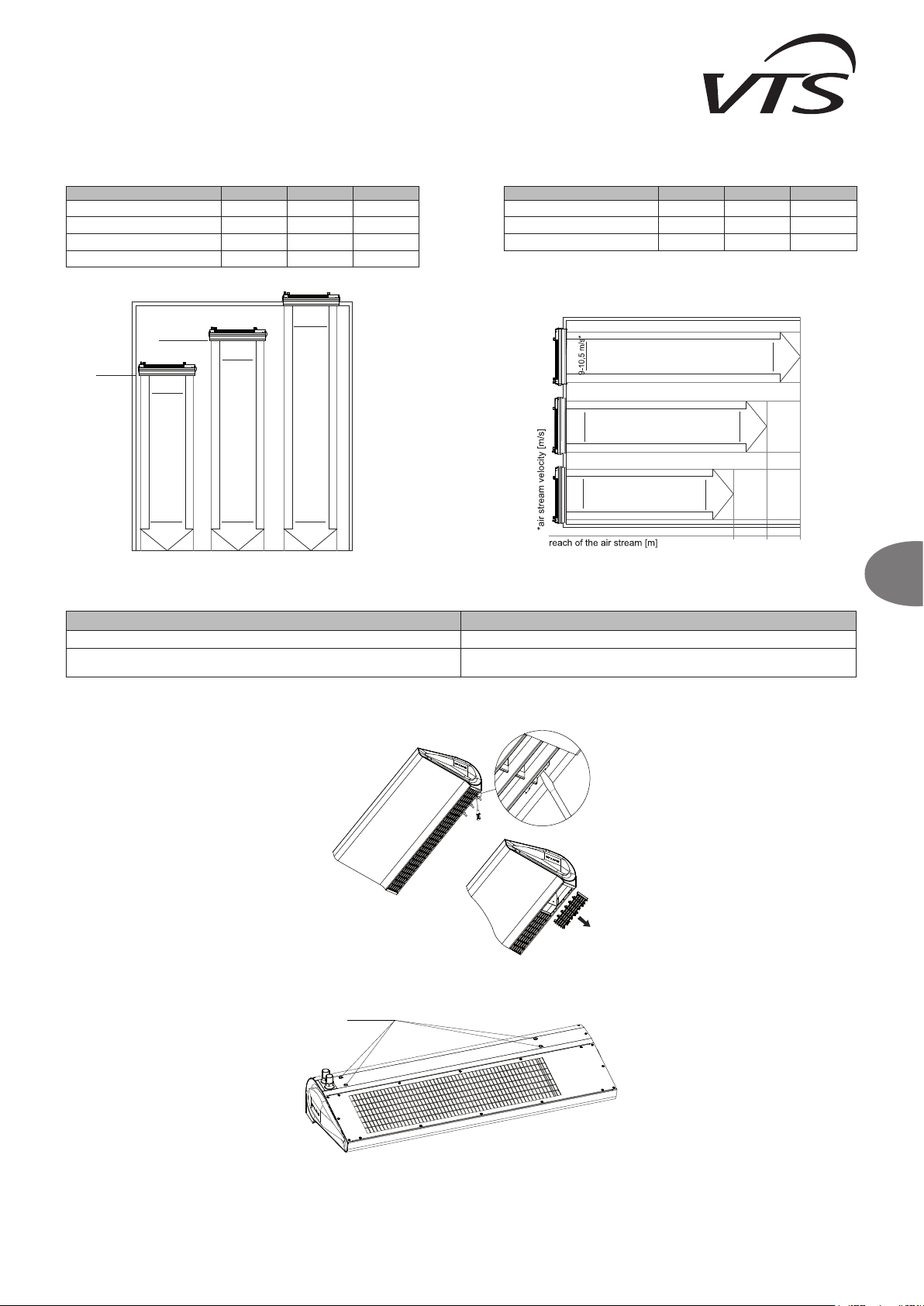
● Installation of the device, according to the guidelines in the Operation and
Maintenance Documentation (among others, the distance from the ceiling). ● Minimum distance: 10 cm from the ceiling
● Correctness of the horizontal alignment of the device.
● Correctness of electrical connections and qualications of
● Parameters of the supply current (among others: voltage, frequency).
● Incorrect covering of the curtain in the suspended ceiling.
● Noise in lower speeds (damaged winding).
● Noise present only in the higher speeds – blocking of the air outlet.
● Type of other equipment working in the facility (e.g. exhaust fans) – increasing
noise may be a result of several pieces of equipment working simultaneously.
● Louder operation of WING devices may be a result of inappropriate place
of assembly : e.g. choking the fan or the acoustic specics of a room.
The fan in the device
is not operational
WING W100-200, EHN
● Correctness and quality of electrical connections and qualications of the tter.
● Parameters of the supply current (among others: voltage, frequency) on the
terminal block of the fan’s engine.
● Operational correctness of other pieces of equipment present in the facility.
● Correct tting of the conduits on the engine side – information available from VTS
Service Department.
● Voltage on the PE conductor (if present, it may indicate a breakdown).
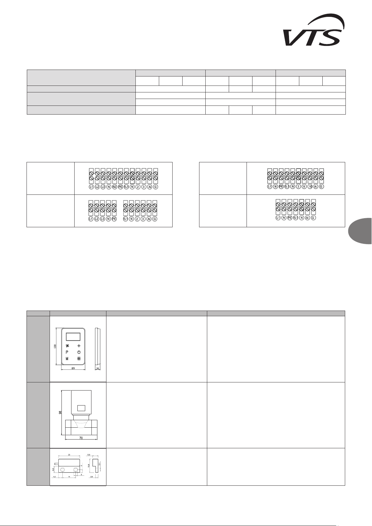
● The electrical connection of the device must be carried out, according to
the diagrams found in the Operation and Maintenance Documentation.
● Damage, incorrect connecting or tting of a wall-mounted controller, other than the
DX contro ller
● It is recommended to check the device by means of connecting the curtain
directly to the power supply and forcing the electric motor's operation
by shorting appropriate clips of the device's terminal strip and then the
terminal strip in the controller.
Damaged casing of the
device
WING W100-200, EHN
● Circumstances in which the defect occurred: remarks on the bill of lading,
inventory issue, condition of cardboard).
● Should the casing be defective, it is required to present photos of the
cardboard and device, as well as photos that conrm the compliance
between the serial number on the device and cardboard. If the damage
was done in transport, it is necessary to prepare a proper statement by the
driver/forwarder that delivered the goods.
Actuator does not open
the valve
● Correctness of electrical connections and qualications of the tter.
● Operational correctness of the thermostat (the characteristic “ticking” when
switching the device).
● Parameters of the supply current (among others: voltage).
● The most important step is to check whether the actuator has reacted
to the electrical impulse. When actuator damage is claimed, a complaint
must be submitted for the damaged element, and the actuator must be
deinstalled from the valve to open the valve mechanically (permanently).
5. START-UP, OPERATION, MAINTENANCE
5.1. START-UP/PUTTING INTO OPERATION
● Prior to the commencing of any installation or maintenance work, disconnect power supply and secure it against unintentional reactivation.
● It is recommended to use lters in the hydraulic system. It is recommended to clean/rinse the system, draining a few litres of water, prior to the connecting of hydraulic conduits (the supply conduits,
in particular).
● It is advised to use vent valves in the highest point of the system.
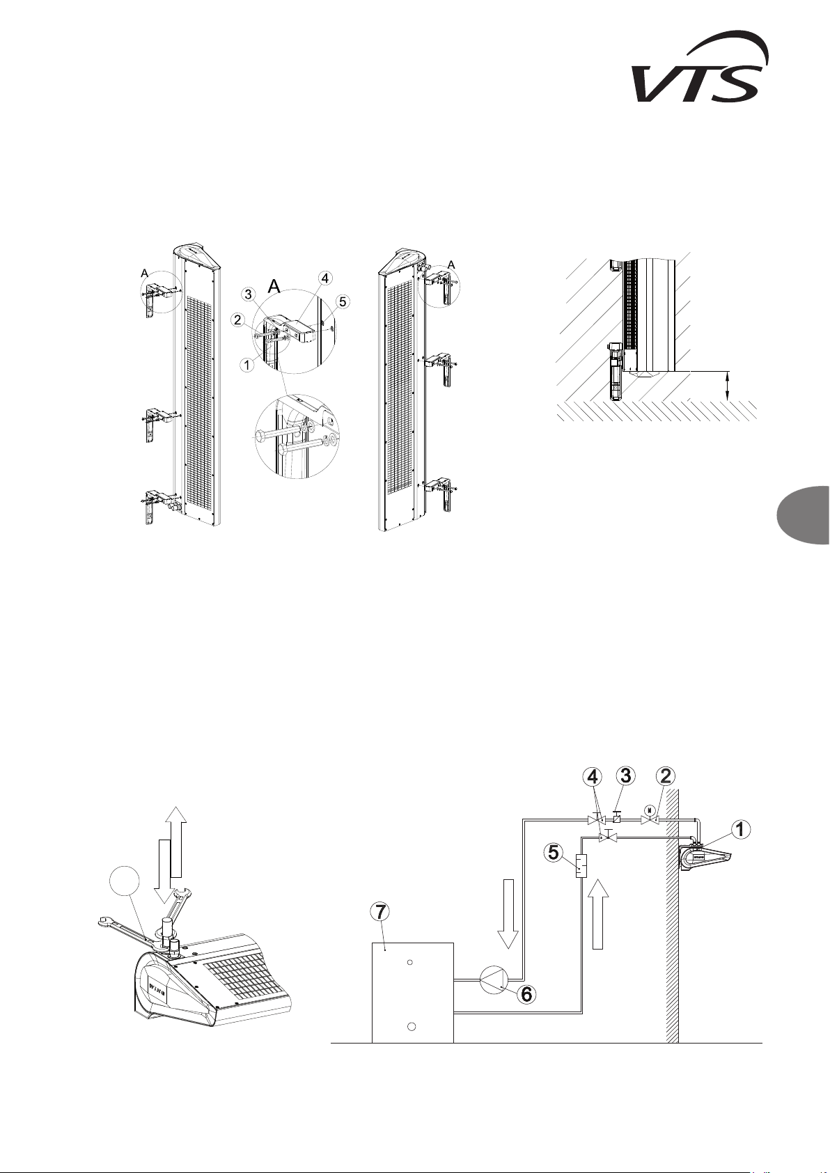
● It is recommended to install shut-off valves directly after the device, should the disassembly of the device be necessary.
● All protective equipment is to be installed before the pressure increases, according to maximum the permissible pressure rating of 1.6MPa.
● Hydraulic connection should be free of any stresses and loads.
● Check the correctness of hydraulic connections (leak-tightness of the vent, collecting pipes, correctness of ttings installation), prior to the initial start-up of the device.
● It is recommended to check the correctness of electrical connections (of automatics, power supply), prior to the initial start-up of the device. It is advised to use an additional, external residual-
current protection.
IMPORTANT! All connections should be carried out, according to this technical documentation and the documentation delivered with automation equipment.
5.2. OPERATION AND MAINTENANCE
● It is advised to carefully analyse all the operational and assembly guidelines listed in chapter 3 and 4.
● The casing of the device does not require maintenance.
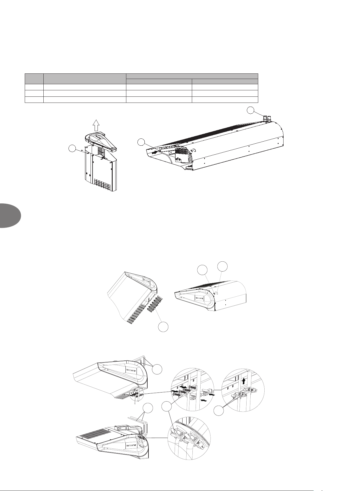
● The heat exchanger should be cleaned on a regular basis from dust and fat deposit. It is especially recommended to clean the exchanger before the heating season with the use of compressed air
from the air intake side (after removing the inlet grid). You should pay special attention to the exchanger's lamellae which are very delicate.
● Should the lamellas be deformed (bent), straighten them with a special tool.
● The fan's motor does not require any exploitation service, the only service activities that may be necessary concern cleaning the air intakes from dust and fat deposit.
● Disconnect phase voltage, if the device is shut down for longer periods of time.
● The heat exchanger does not have any anti-freezing protections.
● It is recommended to provide a periodical purging of the heat exchanger, preferably using compressed air.
● Should the temperature in the room drop below 0°C, with a simultaneous drop of the heating medium temperature, there is a risk that the heat exchanger might freeze (crack).
● The level of air pollutants should meet the criteria allowable concentrations of pollutants in indoor air, for non-industrial areas, the level of dust concentration up to 0.3 g/m³.
● It is forbidden to use device for the duration of the construction works except for the start-up of the system.
● The equipment must be operated in rooms used throughout the year, and in which there is no condensation (large uctuations in temperature, especially below the dew point of the moisture
content). The device should not be exposed to direct UV rays.
● The device should be operated at the supply water temperature up to 90°C with working fan.

11
EN
It is forbidden to place, dispose of and store worn-out electric and electronic equipment, together with other waste. Dangerous compound contained in electronic
and electric equipment have a very adverse impact on plants, micro-organisms, and, most importantly, on humans, as they damage our central and peripheral
nervous system, as well as circulatory and internal system. Additionally, they cause serious allergic reactions. Worn-out equipment is to be delivered to a local
collection point for used electric equipment, which carries out a selective collection of waste.
REMEMBER!
The user of equipment intended for households, and which has been worn out, is obliged to transfer such equipment to a collecting unit that collects worn-out
electric and electronic equipment. The selective collecting and further processing of waste from households contributes to the protection of environment,
reduces the penetration of hazardous substances into the atmosphere and surface waters.
6.2. COMPLAINT PROCEDURE
In order to report a problem with the device or elements of automation, please ll in and send the appropriate form (p.74), using one of the three available ways:
2. Fax: (+48) 12 296 50 75
3. Website: www.vtsgroup.pl\PRODUKT\VTS Service\formularz zgłoszeniowy
Our service department will contact you immediately.
In the case of damage in transport, send a complaint notication, including the delivery documentation (bill of lading, inventory issue) and photographs showing the defects.
Should you have any questions, please contact us, using this telephone number: 0 801 080 073
IMPORTANT! The complaint procedure shall be initiated when the Service Department has received a correctly lled complaint notication, a copy of the purchase invoice and the Warranty
Card, lled by the company that carried out the installation.
7. INDUSTRIAL SAFETY INSTRUCTION
Special instructions concerning safety
IMPORTANT!
● Prior to the commencing of any work related to the device, it is required to disconnect the system, secure it properly and wait, until the fan stops revolving.
● Use stable working platforms and hoists.
● Depending on the temperature of the heating medium, pipes, elements of casing and surfaces of the heat exchanger can be very hot, even after the fan has stopped revolving.
● Sharp edges may be present! Wear gloves, protective shoes and clothing, when transporting the device.
● Strictly observe safety guidelines and industrial safety regulations.
● Loads can be placed only in the previously selected areas on the transporting unit. Protect the edges of the device, when lifting it, using a set of machines. Remember to distribute weight evenly.
● The equipment must be protected against moisture and dirt, and kept in rooms protected against the impact of weather conditions.
● Utilisation of waste: make sure that operating and auxiliary materials, including packaging material and spare parts, are disposed of in a safe, environment friendly manner, according to the binding,
local statutory regulations.
8. CODING
WING W 100 EC
EC – type of motor
100 – length of air curtain 1 [m]
200 – length of air curtain: 1,5 [m]
300 – length of air curtain: 2 [m]
W – water heat exchanger
E – electric heating coil
C – without heat exchanger (cold)
Air curtain WING

12
EN
WING W100-200
WING E100-200
WING C100-200
8. TECHNICAL DATA
8.1 WATER AIR CURTAIN – WING W100-200
Tz– temperature of water at the inlet to the device
Tp– temperature of water at the outlet from the device
Tp1 – temperature of air at the inlet to the device
Tp2 – temperature of air at the outlet from the device
Pg– heating output of the device
Qw – water ow
Δp – pressure drop in the heat exchanger
Parametry WING W100
Tz/Tp[°C] 90/70 80/60 70/50 60/40
Tp1 [°C] 5 10 15 20 5 10 15 20 5 10 15 20 5 10 15 20
III/1850[m³/h]/61dB(A)*
Pg[kW] 17,7 16,3 14,9 13,5 14,8 13,3 11,9 10,5 11,6 10,2 8,7 7,0 8,0 5,1 4,3 3,5
Tp2 [°C] 32,0 35,3 38,5 41,7 27,5 30,7 33,8 36,8 22,8 25,8 28,7 31,3 17,2 17,9 21,8 25,6
Qw[m³/h] 0,8 0,7 0,7 0,6 0,7 0,6 0,5 0,5 0,5 0,5 0,4 0,3 0,4 0,2 0,2 0,2
Δp [kPa] 0,5 0,4 0,4 0,3 0,4 0,3 0,2 0,2 0,2 0,2 0,1 0,1 0,1 0,1 0,04 0,03
II/1350[m³/h]/59dB(A)*
Pg[kW] 15,0 13,8 12,6 11,4 12,5 11,3 10,1 8,8 9,8 8,5 7,2 4,7 5,4 4,6 3,9 3,2
Tp2 [°C] 34,7 37,8 40,8 43,7 29,7 32,7 35,6 38,4 24,4 27,2 29,7 29,7 15,6 19,3 23,0 26,7
Qw[m³/h] 0,7 0,6 0,6 0,5 0,6 0,5 0,4 0,9 0,4 0,4 0,3 0,2 0,2 0,2 0,2 0,1
Δp [kPa] 0,4 0,3 0,3 0,2 0,3 0,2 0,2 0,1 0,2 0,1 0,1 0,1 0,1 0,1 0,04 0,03
I/880[m³/h]/56dB(A)*
Pg[kW] 11,9 10,9 9,9 9,0 9,8 8,9 7,9 6,9 7,6 6,5 4,6 4,0 4,6 4,0 3,4 2,8
Tp2 [°C] 38,5 41,3 44,0 46,7 32,8 35,5 38,0 40,4 26,5 28,8 28,6 31,9 18,0 21,5 24,9 28,4
Qw[m³/h] 0,5 0,5 0,4 0,4 0,4 0,4 0,4 0,3 0,3 0,3 0,2 0,2 0,2 0,2 0,2 0,1
Δp [kPa] 0,2 0,2 0,2 0,1 0,2 0,1 0,1 0,1 0,1 0,1 0,1 0,0 0,1 0,04 0,03 0,02
Parametry WING W150
Tz/Tp[°C] 90/70 80/60 70/50 60/40
Tp1 [°C] 5 10 15 20 5 10 15 20 5 10 15 20 5 10 15 20
III/3100[m³/h]/63dB(A)*
Pg[kW] 31,7 29,3 26,9 24,5 26,9 24,5 22,1 19,8 22,0 19,6 17,3 14,9 17,0 14,5 12,1 9,5
Tp2 [°C] 33,9 37,2 40,4 43,6 29,5 32,7 35,9 39,0 25,1 28,2 31,3 34,3 20,5 23,5 26,4 29,1
Qw[m³/h] 1,4 1,3 1,2 1,1 1,2 1,1 1,0 0,9 1,0 0,9 0,8 0,7 0,7 0,6 0,5 0,4
Δp [kPa] 2,1 1,8 1,6 1,3 1,6 1,4 1,2 0,9 1,2 1,0 0,8 0,6 0,8 0,6 0,4 0,3
II/2050[m³/h]/62dB(A)*
Pg[kW] 26,5 24,5 22,5 20,5 22,5 20,5 18,5 16,6 18,5 16,5 14,4 12,4 14,2 12,1 10,0 7,7
Tp2 [°C] 36,9 40,0 43,0 46,0 32,1 35,1 38,1 41,0 27,2 30,1 33,0 35,7 22,1 24,8 27,5 29,7
Qw[m³/h] 1,2 1,1 1,0 0,9 1,0 0,9 0,8 0,7 0,8 0,7 0,6 0,5 0,6 0,5 0,4 0,3
Δp [kPa] 1,5 1,3 1,2 1,0 1,2 1,0 0,8 0,7 0,9 0,7 0,6 0,4 0,6 0,4 0,3 0,2
I/1420[m³/h]/57dB(A)*
Pg[kW] 21,6 19,9 18,3 16,7 18,3 16,7 15,1 13,5 15,0 13,4 11,7 10,1 11,5 9,8 8,0 4,8
Tp2 [°C] 40,4 43,3 46,1 48,9 35,1 37,9 40,6 43,3 29,6 32,3 34,9 37,4 23,9 26,3 28,5 28,3
Qw[m³/h] 1,0 0,9 0,8 0,7 0,8 0,7 0,7 0,6 0,7 0,6 0,5 0,4 0,5 0,4 0,4 0,2
Δp [kPa] 1,1 0,9 0,8 0,7 0,8 0,7 0,6 0,5 0,6 0,5 0,4 0,3 0,4 0,3 0,2 0,1
Parametry WING W200
Tz/Tp[°C] 90/70 80/60 70/50 60/40
Tp1 [°C] 5 10 15 20 5 10 15 20 5 10 15 20 5 10 15 20
III/4400[m³/h]/66dB(A)*
Pg[kW] 46,9 42,7 39,3 35,9 39,4 36,0 32,6 29,3 32,6 29,2 25,8 22,5 25,7 22,3 18,9 15,4
Tp2 [°C] 34,6 37,9 41,1 44,3 30,3 33,5 36,7 39,8 25,9 29,1 32,2 35,2 21,5 24,5 27,5 30,4
Qw[m³/h] 2,0 1,9 1,7 1,6 1,7 1,6 1,4 1,3 1,4 1,3 1,1 1,0 1,1 1,0 0,8 0,7
Δp [kPa] 5,6 4,9 4,2 3,6 4,3 3,7 3,1 2,6 3,2 2,6 2,1 1,7 2,2 1,7 1,3 0,9
II/3150[m³/h]/65dB(A)*
Pg[kW] 40,9 37,9 34,8 31,9 35,0 31,9 28,9 26,0 28,9 25,9 22,9 20,0 22,8 19,8 16,7 13,7
Tp2 [°C] 36,6 39,8 42,9 46,0 32,0 35,1 38,2 41,2 27,4 30,4 33,4 36,3 22,6 25,6 28,4 31,1
Qw[m³/h] 1,8 1,7 1,5 1,4 1,5 1,4 1,3 1,1 1,3 1,1 1,0 0,9 1,0 0,9 0,7 0,6
Δp [kPa] 4,5 3,9 3,4 2,9 3,5 3,0 2,5 2,1 2,6 2,1 1,7 1,4 1,8 1,4 1,0 0,7
I/2050[m³/h]/60dB(A)*
Pg[kW] 34,0 31,4 28,9 26,4 29,0 26,5 24,0 21,6 24,1 21,6 19,1 16,6 19,0 16,4 13,9 11,3
Tp2 [°C] 39,9 42,8 45,8 48,6 34,8 37,7 40,6 43,3 29,7 32,5 35,3 37,9 24,5 27,2 29,8 32,2
Qw[m³/h] 1,5 1,4 1,3 1,2 1,3 1,2 1,1 1,0 1,1 1,0 0,8 0,7 0,8 0,7 0,6 0,5
Δp [kPa] 3,2 2,8 2,4 2,1 2,5 2,2 1,8 1,5 1,9 1,6 1,2 1,0 1,3 1,0 0,7 0,5

13
EN
8.2 ELECTRIC AIR CURTAIN – WING E100-200
Tp1 – temperature of air at the inlet to the device
Tp2 – temperature of air at the outlet from the device
Pg– heating output of the device
Parametry WING E100 WING E150 WING E200
Tp1 [°C] 5 10 15 20 5 10 15 20 5 10 15 20
III/1850[m³/h]/62dB(A)* III/3150[m³/h]/62dB(A)* III/4500[m³/h]/64dB(A)*
Pg[kW] 2/4/6 2/4/6 2/4/6 2/4/6 4/8/12 4/8/12 4/8/12 4/8/12 6/9/15 6/9/15 6/9/15 6/9/15
Tp2 [°C] 8/11/15 13/16/20 18/21/25 23/26/30 9/12/15 14/17/20 19/22/25 24/27/30 9/10/14 14/15/19 19/20/24 24/25/29
II/1400[m³/h]/55dB(A)* II/2050[m³/h]/60dB(A)* II/3200[m³/h]/63dB(A)*
Pg[kW] 2/4/6 2/4/6 2/4/6 2/4/6 4/8/12 4/8/12 4/8/12 4/8/12 6/9/15 6/9/15 6/9/15 6/9/15
Tp2 [°C] 9/12/16 14/17/21 19/22/26 24/27/31 10/14/19 15/19/24 20/24/29 25/29/34 10/12/16 15/17/21 20/22/26 25/27/31
I/920[m³/h]/53dB(A)* I/1450[m³/h]/55dB(A)* I/2150[m³/h]/59dB(A)*
Pg[kW] 2/4/6 2/4/6 2/4/6 2/4/6 4/8/12 4/8/12 4/8/12 4/8/12 6/9/15 6/9/15 6/9/15 6/9/15
Tp2 [°C] 11/16/21 16/21/26 21/26/31 26/31/36 13/19/26 18/24/31 23/29/36 28/34/41 12/15/21 17/20/26 22/25/31 27/30/36
8.3 WING C100-200 – COLD AIR CURTAIN
EN: * The noise level has been measured within a 3 m distance from the device; reference conditions: semi-open space – wall-mounted device.
Parametry WING W100-200 WING E100-200 WING C100-200
unit of
measure 1m 1,5m 2m 1m 1,5m 2m 1m 1,5m 2m
Maximum width of a single door for one device m 1 1.5 2 1 1.5 2 1 1.5 2
Maximum height of door m 3,7 4
Heating output range kW 4-17 10-32 17-47 2/6 or 4/6 4/12 or 8/12 6/15 or 9/15 -
Maximum ow rate m³/h 1850 3100 4400 1850 3150 4500 1950 3200 4600
Maximum temperature of heating medium °C 95 - -
Maximum working pressure MPa 1,6 - -
Water volume dm³ 1,6 2,6 3,6 - -
Diameter of stub pipe connectors " 3/4 - -
Supply voltage V/ph/Hz ~230/1/50
~230/1/50
for 2kW
~400/3/50
for 2/4/6kW
~400/3/50 ~230/1/50
Power of the electric heater kW - 2 and 4 4 and 8 6 and 9 -
Rated current of the electric heater A - 3/6/max.9 6/11,3/
max.17,3
8,5/12,9/
max.21,4 ---
EC Engine power kW 0,15 0,18 0,26 0,15 0,18 0,26 0,15 0,18 0,26
EC engine rated current A 1,1 1,3 1,9 1,1 1,3 1,9 1,1 1,3 1,9
Weight A 27 36 54 27,5 37 55 23 31 47
IP - 20
Parametry WING C100 WING C150 WING C200
Fan speed III II I III II I III II I
Qp [m³/h] 1950 1500 1050 3200 2250 1500 4600 3400 2340
noise level [dB(A)]* 66 63 57 67 66 58 67 65 61

14
EN
WING W100-200
WING E100-200
WING C100-200
10. TECHNICAL INFORMATION TO THE REGULATION (EU) NO
327/2011 IMPLEMENTING DIRECTIVE 2009/125/EC
EN: IMPORTANT! The drawings with the elements of automatics contain only visualisations of sample products.
*The device does not contain: main switch, fuses and feeder cable
Prior to the dismounting of any cover, shut down the electric power (at least by disconnecting the main switch). Electrical connection of the thermostat, door switch, valve actuator
or control panel is to be carried out before the device is connected to the electric power supply. Any potential changes to the electrical connections between control equipment and
control system of the device are to be carried out in the power off mode (disconnect at least the main switch). All electrical connection should be carried out by a qualied person,
according to the documentation delivered with the device, as well as the afore-mentioned connection diagrams.
WING 100 EC WING 150 EC WING 200 EC
1. 28.5% 27.5% 28.0%
2. B
3. Total
4. 21 21 21
5. VSD-No
6. 2016
7. VTS Plant Sp. z o.o., CRN 0000144190, Poland
8. 1-2-2801-0232 1-2-2801-0233 1-2-2801-0234
9. 0.36kW, 2826m³/h, 145Pa 0.43kW, 4239m³/h, 124Pa 0.61kW, 6006m³/h, 128Pa
10. 1376RPM 1370RPM 1372RPM
11. 1.0
12.
Device disassembly should be performed and/or supervised by perperly qualied personnel having sufcient
knowledge. Contact a certied waste disposal company in your region. Explain what is to take place in terms of device
disassembly and subassembly securing. Disassemble the device using general procedures applied in mechanical
engineering.
WARNING
The fan unit consists of heavy elements. These elements can fall down during disassembly, causing the death, severe
injury of the staff, as well as material damages.
Learn the following safety principles:
1. Disconnect the power, including all related subsystems.
2. Prevent the device from restarting.
3. Make sure the device is disconnected from power supply.
4. Secure or isolate all elements which are powered and situated nearby.
To restore power supply, reverse the procedure.
Components:
In its dominant part, the device consists of of components made of steel, copper, aluminum and plastics, in varying
proportions (the rotor is made of SAN - styrene, acrylonitrile, structural material with the addition of 20% of glass
ber) and rubber (neoprene) sockets/bearing hubs. The components must be sorted before recycling according to the
following material categories: iron and steel, aluminum, copper, non-ferrous metals, e.g. winding (winding insulation
will be burnt in the course of copper recycling, insulation materials, electrical wires, electronic waste (condenser,
etc.), plastic elements (fan rotor, winding shields, etc.), rubber elements (neoprene). The same applies to textiles
and cleaning substances used to disassemble the components. Elements should be separated according to local
regulations or by a specialist recycling company.
13.
Long period of defect-free operation depends on maintaining the product / device / fan in the scope of working
parameters specied by the slection and usage software, according to the intended purposes specied in the
operation and maintenance documentation enclosed to the device. To ensure correct operation of the device, always
adhere to the technical documentation, and particularly chapters: assembly, startup, use and maintenance.
14. Fan housing, internal proles
*1) general efciency (η)
2) measurement category used to determine the energy efciency
3) efciency category
4) efciency coefcient in the point of optimal energy efciency
5) whether rotational speed regulation was taken into account in the calculation of fan efciency
6) year of manufacture
7) manufacturer’s name or trademark, business register number and place of manufacture
8) product model number
9) rated motor power consumption (kW), ow volume and pressure in the point of energy efciency
10) rotations per minute in the point of energy efciency
11) characteristic coefcient
12) essential information to facilitate disassembly, recycling or dispose of the product after the end of its use
13) essential information to minimize the effect on the environment and to guarantee optimum use period, referring to disassembly, use and technical service of the fan
14) description of additional elements used in determining the energy efciency of the fan

The company submitting the notication:
The company that installed the equipment:
Date of notication:
Type of device:
Factory number*:
Date of purchase:
Date of installation:
Place of installation:
Detailed description of defect:
Contact person:
Name and surname:
Telephone:
E-mail:
* This eld must be lled, if the complaint notication refers to the following equipment: VOLCANO and WING air curtains.
VTS POLSKA Sp. z o.o.
Al. Grunwaldzka 472 A
80-309 Gdańsk
Polska
www.vtsgroup.com
EN
11. Complaint Form
This manual suits for next models
11
Table of contents
Other VTS Medical Systems Heater manuals

VTS Medical Systems
VTS Medical Systems WING W100-200 Guide

VTS Medical Systems
VTS Medical Systems WING PRO Guide

VTS Medical Systems
VTS Medical Systems WING W100-200 Guide

VTS Medical Systems
VTS Medical Systems WING W100 Guide

VTS Medical Systems
VTS Medical Systems VOLCANO VR Series Guide

VTS Medical Systems
VTS Medical Systems WING W100-200-EC User manual