IEC Centra-CL3 Series User manual
I
j .
..
:'.>i
IE<:
.,
·'
.
'·
OPERATION·.··
MANUAL
OM3750
I
Revision 0
~~-i~~l~l~::~ge
Cit~
NC)//
~1e1.·
+;
2io~·ii•~
240
VAC,
60/60 Hz
~k-~I.~~~~
Cenbifuge
9~t.
No.~
..
·.·
•....
·.·
3765
.....
~
2~V~C.
·
60
Hz
C~tJ
ff:C)~
{
37.6
....
a29,
j$f)~
240 VAC,
50
Hz
(;•t•
~o.
37,7
....
aa~tVA(;,
60
Hz
..df.11~~
r
-·~UALITY
IEC
CENTRIFUGES
V"Jl.
IEC
INTERNATIONAL
EQUIPMENT
COMPANY
300 SECOND
AVENUE,
NEEDHAM HEIGHTS, MA 02194
U.SA
TEL.
(781) 449-8060
•TOLL
FREE (800) 843-1113
•FAX
(781) 444-6743
f
l
1 Introduction
1.1
General Product Description
Centra-CL3 series units are high-speed, multipurpose
centrifuges, used
in
medical, industrial, and scientific
applications.
The CL3 Series
is
available in two versions: ventilated
(Centra-CL3) and refrigerated (Centra-CL3R). Sections
of
this manual that apply
to
the refrigerated version will be
designated Centra-CL3R
or
refrigerated only.
Both units accommodate a wide variety
of
rotors, including
fixed angle, swinging bucket, and fixed horizontal designs.
They can process tubes, bottles, microplates, microcapillary
tubes, cytological slide carriers, and microsample tubes.
The units can centrifuge up to one liter
of
fluid in a single
operation.
Each centrifuge has an easy to use front panel that provides
two modes
of
operation: Manual and Programmed.
Manual mode
is
used for entering temperature (CL3R only),
speed/force, and time values for individual runs.
Program mode allows you to define and save a maximum
of
ninety-nine specific sets
of
run parameters, to recall and
reuse.
Centra-CL3 Series Operation Manual
1
I
t TABLE
OF
CONTENTS
.Centra-CL3 Series Operation Manual
.Chapter 1: Introduction
1.
1 General Product Description ............................................................................... 1
1.2 About this Manual .............................................................................................. 2
1.3
Warnings, Cautions,
and
Notes ........................................................................... 3
Chapter 2: Installation
2.1
Receiving the Unit .............................................................................................. 5
2.2 Site Preparation .................................................................................................. 5
2.3 Power Configuration........................................................................................... 7
2.4 Moving the Unit.................................................................................................. 8
2.5 The Front Panel .................................................................................................. 8
.Chapter 3: Operation
3.
1 Rotor and Accessories ......................................................................................
13
3
.2
Starting and Stopping a Run .............................................................................
17
3.3 Stored Programs............................................................................................... 20
3
.4
Centra-CL3 Series Refrigeration .......................................................................
21
3.
5 Diagnostic Messages and Error Codes ..............................................................
23
Chapter 4: Applications
4.1
Introduction......................................................................................................
25
4.2 Speed and Force Tables .................................................................................... 27
4.3
Derating for Dense Samples Table ....................................................................
36
4.4 Chemical Resistance Table ................................................................................ 39
4.5 Decontamination Table ..................................................................................... 40
4.6 RCF Nomograph ..............................................................................................
41
Chapter
5:
Maintenance
5.1
Introduction......................................................................................................
43
5.2 Care and Cleaning.............................................................................................
43
5.3
Cover Interlock Bypass Switch ......................................................................... 46
5.4 Condition
of
Returned Equipment..................................................................... 47
5.5
Warranty........................................................................................................... 47
Chapter 6: Specifications
Unit Specifications................................................................................................... 49
Centra-CL3 Series
Operation
Manual
I

The CL3 Series features a maintenance-free, brushless
motor, and an easy-to-use front panel, which provides three
versatile timing modes: automatic timed run, momentary
spin, and continuous operation (hold mode). Acceleration
and brake rates may be controlled,
to
optimize runs: rapid
for fast separations or slow for delicate samples. Repeat
runs, with the same speed and time settings, may be
achieved at the touch
of
a
key.
A fail-safe cover interlock insures that
the
cover is closed,
before a run can begin, and keeps the cover closed, until the
rotor has reached a safe low speed (below 100 rpm), even in
the event
of
a power failure.
The rugged steel cabinet and rigid construction provide
quiet operation and long term reliability.
1.2 About This Manual
The Operations Manual contains all
of
the
information
needed to install, operate, and maintain a CL3 Series
centrifuge. Refrigerated and ventilated models operate
similarly, and any differences are highlighted and noted,
throughout this manual. This manual, also, contains speed
and force, derating, chemical resistance, and
decontamination tables. The last chapter lists the units'
specifications.
This manual
is
written for centrifuge operators. In addition
to operation information, it contains a few basic
troubleshooting techniques, and a chapter on maintenance.
This Operation Manual
is
not a guide for servicing
centrifuge units.
Centra-CL3 Series Operation Manual
2
..
.t
,!
~·,
."
! ;
I
1.3 Warnings, Cautions, and Notes
The tenns warning, caution, and
note
have specific
meanings
in
this manual.
• A
Warning
advises against certain actions
or
situations
that could result
in
personal injury.
• A
Caution
advises against actions
or
situations that
could damage equipment, produce inaccurate data, or
invalidate a procedure.
• A Note provides useful infonnation regarding an
operation, function,
or
procedure.
Centra-CL3 Series OperationManual
3

2 Installation
t
- !
-
2.1
Receiving the Unit
·
2.2
Site Preparation
International Equipment Company (IEC) ships the
centrifuge
in
a carton that protects it from shipping hazards.
Follow the unpacking instructions on the carton.
Be
sure
to
complete and return the postage-paid warranty card.
The unit normally resides on a bench top. The Centra-CL3
(ventilated model) can be placed
in
a cold room (no colder
than 0°C), for processing temperature-sensitive samples.
When you remove the centrifuge from a cold environment,
do not operate for a minimum
of
two hours, so that any
condensation will evaporate.
Note: When used
in
a cold room environment, some bearing
noise may become evident. The bearing lubricant thickens
at low temperatures.
As
the centrifuge speeds up, it
is
thinned and distributed more evenly. Once this occurs, any
noise should subside.
Centra-CL3 Series Operation Manual
s
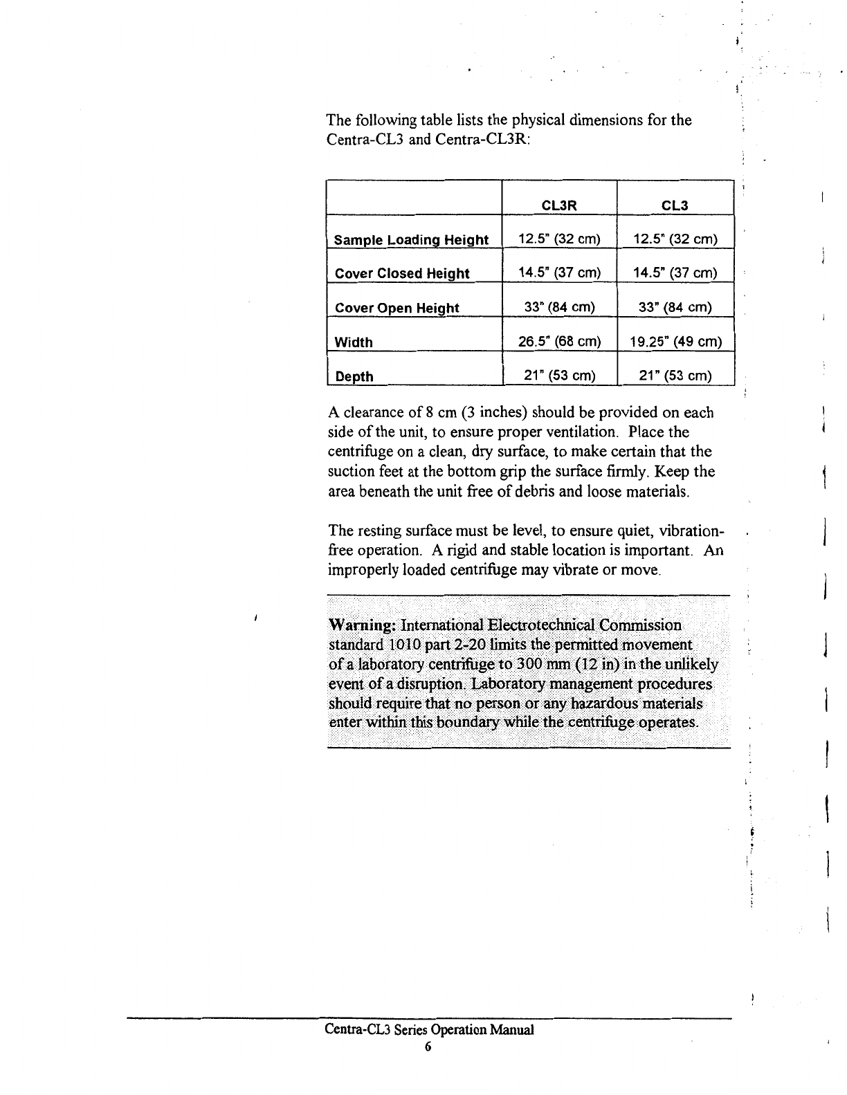
The following table lists the physical dimensions for
the
Centra-CL3 and Centra-CL3R:
CL3R
CL3
Sample
Loading
Height
12.5" (32 cm) 12.5" (32 cm)
Cover
Closed
Height
14.5" (37 cm) 14.5" (37 cm)
Cover
Open
Height
33" (84 cm) 33" (84 cm)
Width
26.5" (68 cm) 19.25" (49 cm)
Depth
21" (53 cm) 21" (53 cm)
A clearance
of
8 cm (3 inches) should
be
provided on each
side
of
the unit,
to
ensure proper ventilation. Place
the
centrifuge on a clean, dry surface,
to
make certain that
the
suction feet at the
bottom
grip the surface firmly. Keep
the
area beneath the unit free
of
debris and loose materials.
The resting surface must
be
level,
to
ensure quiet, vibration-
free operation. A rigid and stable location is important. An
improperly loaded centrifuge may vibrate
or
move.
~al"Jling;·.•1nternationa1••~lectrot~(;hnlcal
••
G<)nunission•.
~t3#4?rcf•i<no••part;·g¢20•A#rlt8••th~
pe~tie<l••rti()velJleJ1~•
•
<>fa.•fabol"atc>&·•ce11trifUge••t()•$QQ~H@IP)iri·the••uillikely
•:JZQ~ai;e~~~~~t~~1;~~;~~rl~~i~~sP~1i:!~zs•.
eriier•\ViiliiJit~•·bqun(iaw.W-lii~~
tp~
petit#fuge
qperat~s.
Centra-CL3
Series
Operation
Manual
6

2.3
Power Configuration
Power Cord
Circuit Breaker
The CL3 Series uses
AC
power in different configurations,
appropriate for use throughout the world. Please check
the
catalog number
of
the model that you have purchased,
to
ensure that the machine you have is the proper power
configuration. Forbest results, the refrigerated centrifuge,
Centra-CL3R, should be used
on
a dedicated line.
Variations in line voltage
or
frequency affect the
unit's
speed and other characteristics. Less than nominal line
voltage may prevent the centrifuge from reaching maximum
published specifications
of
speed and/or temperature.
Power line voltage, at some locations, may sag, when
the
refrigeration system turns on.
The unit requires a grounded power supply
(3
prong
outlet).
If
your facility does not have grounded
power
outlets, arrange for a proper grounding. The power
cord
plugs in on the left rear side
of
the unit.
~=~o~=:i:ili~~~t~~~e
powerplug tbatdoes not
have
~
gr~Undilig
pin.
··
·.···
··
The
power
cord
provided withthetiJlltiscorrectly rated
forthe
highest
current
demand.
This
poweirord.shouldJ1ot
be
interchanged
with
cords
from
equipinentwitb.Jower current
demand.
Exchange
of
power
cords
befiVeell
equipment•may
createa
fire
hazard.
The system provides
an
automatic circuit breaker, for
emergency situations, such as power surges, that could
damage the unit.
If
the circuit breaker trips:
1.
Unplug the unit.
2.
Press the white button, on the left side
of
the unit.
3.
Plug the unit back
in.
Centra-CL3 Series Operation Manual
7
2.4 Moving the Unit
2.5 The Front Panel
©
Suction cups, at the bottom
of
the unit, keep it anchored
to
the work surface. Keeping the unit stationary is a safety
feature.
To move the unit to a new location:
1.
Check that the new site meets the criteria
in
Section
2.2., before moving the unit.
2.
Position a flat object, such as a tongue depressor, near a
suction cup at the bottom
of
the unit.
3.
Lift up
an
edge
of
the cup, and insert the flat object far
enough to break the vacuum seal.
4.
When
all
four cups are disengaged, lift the unit from the
work surface.
Caution: When the unit
is
in
its new location, ensure that
the suction cups adhere correctly to the work surface.
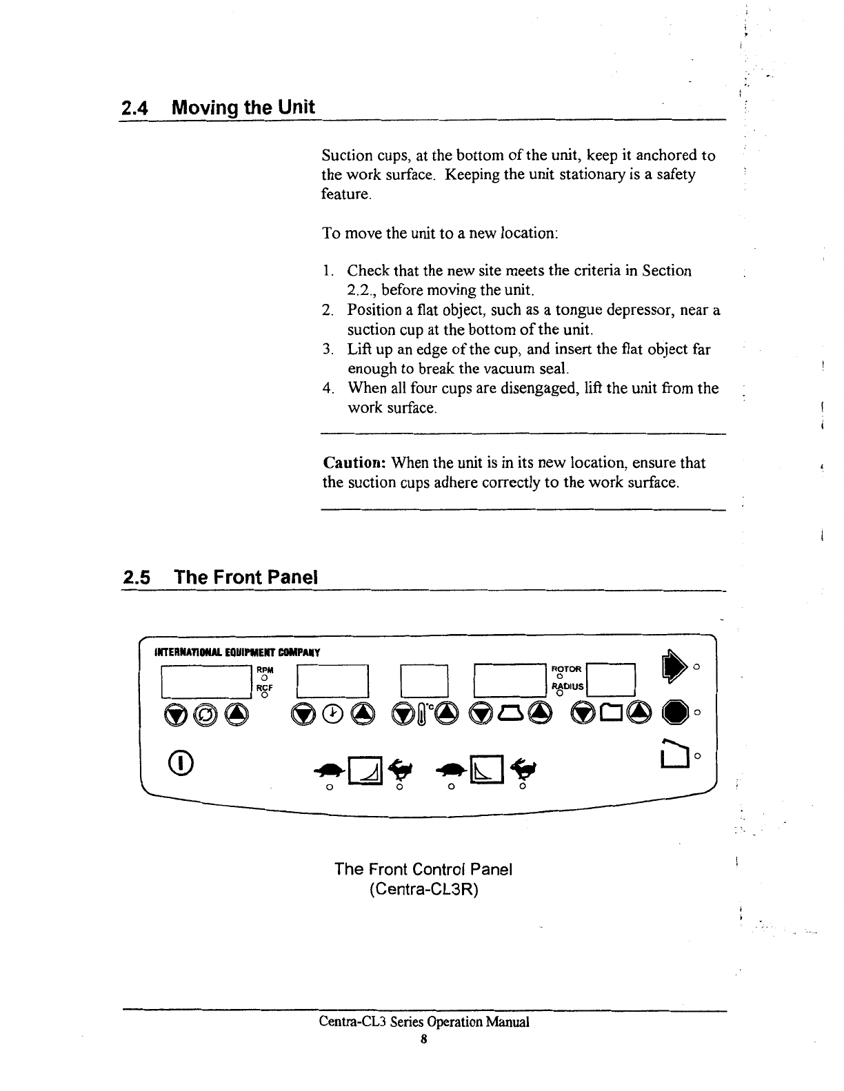
The Front Control Panel
(Centra-CL3R)
Centra-CL3
Series
Operation
Manual
8

© On/Off
key:
The On/Offkey must be activated,
to
enable
use
of
the front panel. This key applies power
to
the
control panel and refiigeration system (Refrigerated model
only). The On/Offkey is inoperative during actual runs.
Stop a run with the STOP key. Refrigerated models
display chamber temperature whenever they are plugged in,
but will not cool down
if
the unit
is
off
The red STOP
light indicates that the centrifuge is plugged
in.
The control panel contains numeric displays for
RPM/RCF
(Speed/Force), Time, and Temperature (Refrigerated only).
These displays have
two
states
or
modes: Actual (bright
display) and Set (dim display).
In Actual mode (bright display), they indicate current run
conditions, such as:
• rotor speed
or
force
• elapsed time of,
or
time remaining
in,
the run
• actual temperature (Refrigerated only).
In Set mode (dim display), the display indicates the desired
settings for the run. Set mode
is
operative:
• whenever you use the up and down arrows
• briefly, at the start
of
a run
• briefly, after the unit
is
switched ON
The display
is
bright, when it shows Actual run conditions.
The display
is
dim, when it shows Set parameters.
The
numeric displays can, also, display warning
or
error
messages (see Section 3.5). Descriptions
of
the displays
appear on the following pages.
Centra-CL3 Series Operation Manual
9
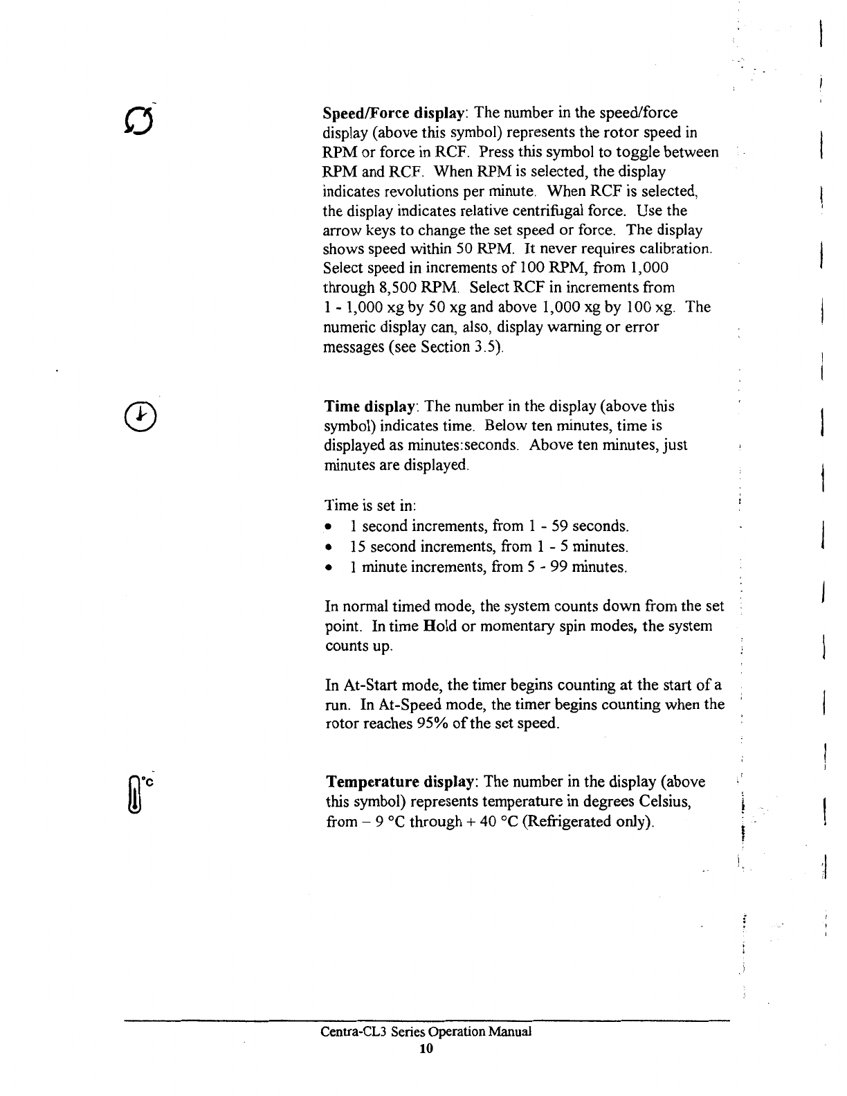
0 Speed/Force display: The number in the speed/force
display (above this symbol) represents the
rotor
speed
in
RPM
or
force in RCF. Press this symbol
to
toggle between
RPM
and RCF. When
RPM
is selected, the display
indicates revolutions per minute. When
RCF
is selected,
the display indicates relative centrifugal force.
Use
the
arrow keys
to
change the set speed
or
force.
The
display
shows speed within 50 RPM. It never requires calibration.
Select speed in increments
of
100 RPM, from 1,000
through 8,500 RPM. Select RCF in increments from
1 - 1,000 xg by 50 xg and above 1,000 xg by 100 xg. The
numeric display can, also, display warning
or
error
messages (see Section 3.5).
Time display: The number
in
the display (above this
symbol) indicates time. Below ten minutes, time is
displayed as minutes:seconds. Above ten minutes,
just
minutes are displayed.
Time is set
in:
• 1 second increments, from 1 -
59
seconds.
•
15
second increments, from 1 - 5 minutes.
• 1 minute increments, from 5 - 99 minutes.
In normal timed mode, the system counts
down
from the set
point. In time
Hold
or
momentary spin modes,
the
system
counts up.
In At-Start mode, the timer begins counting
at
the
start
of
a
run. In At-Speed mode, the timer begins counting when the
rotor
reaches
95%
of
the set speed.
Temperature display: The number
in
the display (above
this symbol) represents temperature
in
degrees Celsius,
from - 9 °C
through+
40 °C (Refrigerated only).
Centra-CL3 Series Operation Manual
10
:I

Program
key: This key saves the currently displayed
desired settings as stored programs I through 99 (see
Section 3.3). The numeric display (above this symbol)
shows the stored program number and mode
of
operation
(see Section 3.2).
Rotor/Radius
Key: The display (above this symbol)
indicates the selected rotor number
or
the
rotor radius,
in
centimeters. The rotor/radius key toggles between the two
displays. The applicable IEC rotor numbers are supplied
in
the memory, along with their maximum radii, in
centimeters. To select a rotor number, toggle
to
ROTOR,
and press an arrow key under the rotor/radius display. To
change the radius, toggle to RADIUS, and press an arrow
key under the rotor/radius display.
Note
that the radius
cannot be changed to a radius larger than the maximum
radius,
or
less than the minimum radius, for the selected
rotor.
Use the arrow keys to view or change the Set parameters
for Speed/Force, Time, Temperature (Refrigerated only)
Rotor/Radius,
or
Program. The first time the key is
pressed, the numeric display switches from Actual readings
to Set parameters, without changing them.
If
you press the
key a second time, the selected parameter increases
or
decreases once for each depression.
If
you hold the key
down, the setting
will
keep changing, until you release the
key.
The longer you hold the key, the more rapidly the setting
changes. Hold a key down, to approach a desired setting.
Then, press the up or down key, repeatedly, to select the
exact setting. When you release the arrow keys for
3 seconds, the display returns to the Actual readings.
Centra-CL3 Series Operation Manual
11

Acceleration and Braking
•
Gentle acceleration and braking can be selected, when
centrifuging delicate samples. The gentle settings avoid
mixing
of
density gradients
or
breakup
of
pellets.
This key controls rotor acceleration up to 400 RPM.
If
the
yellow light over the rabbit is lit,
full
acceleration
is
selected.
If
the yellow light over the turtle
is
lit, slow
acceleration
is
selected. Slow acceleration takes from
15
to
35 seconds to achieve 400 RPM, depending on the rotor
and its contents. After 400 RPM,
full
acceleration
is
applied, until the set speed is reached.
This key controls rotor braking.
If
the yellow light over the
rabbit
is
lit,
full
braking
is
selected.
If
the yellow light over
the turtle
is
lit,
slow braking is selected. (This means the
rotor
will
coast down from 600 RPM.)
If
both lights are
out,
all
braking is disabled; and the rotor
will
coast from
operating speed to a stop.
This key starts a run. A run is governed by the Set
parameters (manual
or
programmed). The associated green
light blinks, until the rotor reaches 95%
of
the set run
speed. The light stays on until the end
of
the run.
This key stops a run. (A run will, also, stop automatically
when the set time has elapsed
or
the start key
is
released, in
momentary mode.) The red light will flash, to indicate the
rotor
is
still slowing down (braking
or
coasting). When the
run ends, the red light stays on, indicating that the rotor has
stopped.
This key unlocks the cover. This key
is
inoperative
if
a run
is
in
progress. Pressing it will not stop the run. The cover
will not unlock, until the rotor has slowed to below 100
rpm. The cover will open automatically, on ventilated units
only, at the end
of
a run.
Centra-CL3
Series
Operation Manual
12
l
l
}
I
l
1

3 OPERATION
3.1
Rotor and Accessories
A balanced
lo.ad
is
essential for all centrifuges.
An
unbalanced load produces vibration, and can damage the
unit. A 2 gram load imbalance, at a speed
of
4600 RPM,
imparts force equivalent to
9.
I kg (20 pounds) at rest.
Always ensure that the rotor is loaded symrn.etrically, with a
full
complement
of
accessories, and a
full
(or paired) set
of
tubes. Tube adapters should also be installed symmetrically.
IEC rotors are dynamically balanced at the factory. IEC
matches removable parts (trunnion rings, shields, buckets,
and carriers) to within I gram, and stamps the weight on
each piece. Check these markings, whenever you
interchange parts, to ensure that opposite parts are matched.
Ensure that the total weight
of
samples and removable
parts, loaded
in
opposing positions, are equal
in
weight, to
within 1 gram. The position numbers, present on many
rotors and adapters, identify opposing tube positions.
To
obtain good dynamic balance, opposite loads must not
only be equal
in
mass, but must, also, have the same centers
of
gravity. Opposing containers must be alike
in
shape,
thickness, and distribution
of
glass
or
plastic. This
is
especially important for large containers.
Centra-CL3 Series Operation Manual
13

Rotor Balance
Tubes loaded into swinging bucket
rotors
must be
symmetric, around the
ax.is
of
rotation. Verify this by
rotating the entire rotor 180°,
by
hand.
The
loads should be
in
the same apparent positions (not mirror images). In
addition, the loads within each bucket must, also, be
symmetric around the bucket's pivot axis. Verify this
by
ensuring that each bucket
is
loaded so that it does not tilt
from the vertical, when the rotor is
at
rest. Maintaining
balance within each bucket ensures that
the
bucket and the
tubes swing out to horizontal, when
the
rotor reaches
operating speed, applying centrifugal force toward the
bottom
of
the tubes. Failure to achieve full swing-out
causes vibration and premature wear
of
the rotor and the
motor.
Samples oflike (similar) specific gravities may be processed
in
the same run, provided that the samples
of
the same type
are balanced around the rotor, as though they were the only
pairs
in
the rotor.
Caution:
Do
not exceed maximum rated speed for each
rotor/accessory combination. Maximum rated speeds can
be found
in
Section 4.2 -Speed
And
Force
Tables.
Load tubes
in
the following manner:
1.
Load two tubes at positions:
9
and
18.
2. Load four tubes at positions:
1,
5 and 10,
14
or
7, 3 and 16,
12
3.
Load six tubes at positions:
1,
9, 5 and 14, 18,
10
or
7, 9, 3 and 12, 18,
16
4.
Loading
an
odd number
of
tubes is not
recommended.
Centra-CL3 Series Operation Manual
14
I
I
Ir -

V~ration
(
Rotor Installation
I.
PRESS
UP
HERE
AND
HOLD
Rotor Removal
All
centrifuges have critical speeds, at which vibration
occurs.
As
the
speed increases, beyond
the
critical speed,
vibration will cease. This inherent condition, also,
occurs
during deceleration. An imbalanced load intensifies
these
critical vibrations. Do not continuously operate this
centrifuge at observed critical speeds.
To
install the #243 rotor:
1.
Press the disk (located
on
the
underside
of
the
rotor)
to
the rotor.
2. Slide the
rotor
over
the shaft, until it snaps into place.
Release
the
disk.
3. Pull the rotor straight up, to insure a positive lock.
3.
PULL
STRAIGHT
UP
ON
ROTOR
TO
CONf
IRM
SECURE
ATTACHMENT
0 0
2.
SLIDE
ONTO
SHAFI
AND
RELEASE
To remove the 243 rotor:
1.
Press the disk (located on the underside
of
the
rotor)
to
the rotor.
2.
Lift the
rotor
straight up.
3.
Release the disk.
Centra-CL3 Series Operation Manual
15
Rotor Adapter To install the shaft adapter for an existing rotor:
1.
Press the adapter disk, and slide the adapter over the
rotor shaft. Release the disk.
2.
Pull the adapter straight up, to insure a positive lock.
3.
Align the rotor keyway with the key on the shaft
adapter, and place the rotor onto the adapter.
4.
Tighten the rotor locking nut (with the provided
wrench), until it tightly engages the rotor.
To remove existing rotors from the shaft adapter:
1.
Remove any sample tubes, shields, buckets, and other
accessories, from the rotor.
2.
Unscrew and remove the locking screw.
3.
Grasp the rotor, and rock
it
front-to-back, and side-to-
side.
4.
Remove the rotor from the shaft.
Centra-CL3
Series
Operation
Manual
16

3.2 Starting
and
Stopping a
Run
Read Section 2.5, for a general description
of
the front
panel. The settings displayed on the front panel always
govern the operation
of
the unit. 'fhe number
or
symbol,
above the Program icon, shows the unit's operating mode.
It is important that the unit be in the correct mode for the
desired operation.
These digits and symbols are displayed above the program
icon. They can be any
of
the following:
blank The unit
is
in
manual operation.
1-99 The unit
is
under control
of
the displayed stored
program number.
C The unit
is
set to Rapid Condition, a special
program discussed
in
Section 3.4.
The display indicates the last parameters selected for each
Program mode operation.
Centra-CL3
Series
Operation
Manual
17
Manual Operation
For
manual operation, set the mode so that the display
above the Program icon
is
blank. Select the desired
temperature (CL3R only), speed/g-force, run time,
acceleration mode, and braking mode. Press START, to
start the spin.
The minutes display counts down, and displays the time
remaining
in
the current spin, during manual operation.
The specified run time begins when the
START
key
is
pressed,
or
when the rotor reaches 95%
of
set speed (see
Timing Mode). Braking begins when the elapsed time
reaches this desired setting. Run time does not include
braking time.
The spin
will
stop automatically, at the end
of
the desired
interval. A run can, also, be stopped, at any time,
by
pressing the
STOP
key.
The settings can be changed during a manual run. These
changes affect the run
in
progress.
If
the time setting is
changed, during a run, the unit adjusts the count-down
timer, to display the revised setting as the total time
of
the
run.
If
the new time selected
is
less than the elapsed time,
the run
will
end.
The unit's mode (settings) cannot be changed during a
program mode spin.
Centra-CL3
Series
Operation Manual
18
- j
.Timing Mode Fourtiming modes are available on these units:
To
select a
timing mode, press the down arrow, under the time display,
until the time goes below zero, and the appropriate symbol
is
displayed.
Momentary
Mode
(--)
-Momentary spin is useful for
easily separated samples, for simultaneous mixing
of
samples, and
to
deposit condensate droplets at the bottom
·of
the tube.
For
momentary spin, set the mode so that three dashes (---)
appear above the Clock icon. Select temperature
(CL3R
only), speed/g-force, acceleration mode, and braking mode,
as for manual operation.
Press and hold the
START
key.
The run starts when you
press the key, and ends when you release the key. In this
mode, you can perform very quick separations
or
protocols.
During a momentary spin, the unit displays actual values,
not desired settings. The time display counts upward, and
displays the elapsed time since the
START
key was
pressed.
Hold
Mode
(HLd)
-
For
hold mode (operation without
preset time limit), set the mode so that
HLd
appears in the
Time display.
Select temperature (CL3R only), speed/g-force, acceleration
mode, and braking mode, as with manual operation. Press
and release the
START
key. The run starts when you press
the
key,
and stops only when you press the
STOP
key.
Hold mode
is
like manual operation, except that the time
setting
is
not used. During a run
in
hold mode, the time
display counts upward, and displays the elapsed time
of
the
spm.
At-Start
Mode
(ACC) -The set time
will
start counting
down
at
the beginning
of
acceleration (when the start key
is
pressed). The unit
is
originally set to this mode.
At-Speed
Mode
(SPd) -The set time
will
start counting
down, when the rotor has reached 95%
of
set speed. The
display
will
alternately show the set time and SPd, during
acceleration to 95%
of
the set speed.
Centra-CL3 Series Operation Manual
19
This manual suits for next models
1
Table of contents
Other IEC Laboratory Equipment manuals

Popular Laboratory Equipment manuals by other brands

Hanna Instruments
Hanna Instruments Groline HI981413 instruction manual

Bego
Bego Gelovit 200 Translation of the original instructions

Hanna Instruments
Hanna Instruments HI922 instruction manual

biochrom
biochrom EZ Read 400 quick start guide

Julabo
Julabo EH operating manual

Sutter Instrument
Sutter Instrument TRIO MP-245A Operation manual


NuAire
NuAire LabGard NU-543-300J Operation and maintenance manual

Kendro
Kendro Heraeus Biofuge haemo Instructions for use

Graco
Graco GCI Series instructions

Tecno-gaz
Tecno-gaz Multisteril Fast Technical manual

Parker
Parker Domnick Hunter 060 Series user guide

Zimmer Biomet
Zimmer Biomet GPS III Processing instructions