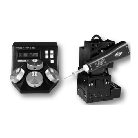
TRIO MP-245A FOUR-AXIS MICROMANIPULATOR SYSTEM OPERATION MANUAL – REV. 3.12B (20191001)
TABLE OF CONTENTS
DISCLAIMER .......................................................................................................................................3
SAFETY WARNINGS AND PRECAUTIONS....................................................................................3
Electrical ..................................................................................................................................................3
Avoiding Electrical Shock and Fire-related Injury..............................................................................3
Electromagnetic Interference ............................................................................................................3
Operational ..............................................................................................................................................3
Other.........................................................................................................................................................4
Handling Micropipettes..........................................................................................................................4
1. INTRODUCTION.............................................................................................................................9
1.1 Structure of the TRIO MP-245A Documentation Package .........................................................9
1.2 Components of the TRIO MP-245A System..................................................................................9
1.3 Overview ..........................................................................................................................................10
1.3.1 Features.....................................................................................................................................10
1.3.2 Description................................................................................................................................10
2. INSTALLATION ............................................................................................................................13
2.1 Mounting Instructions ...................................................................................................................13
2.1.1 Mounting the TRIO MP-245/M to the Stand or Platform ..................................................13
2.2 Headstage Mounting ......................................................................................................................14
2.3 Other Accessories............................................................................................................................14
2.4 Electrical Connections and Initial Operating Instructions........................................................14
2.5 ROE/Controller Rear Panel Controls and Configuration...........................................................15
2.5.1 Power Switch............................................................................................................................15
2.5.2 Rear-Panel Configuration Switches.......................................................................................16
2.5.2.1 Rear-Panel Switches 1, 2, 3 and 4: Knob Rotation Directionality for Forward (+)
Movement .......................................................................................................................................16
2.5.2.2 Rear-Panel Switch 5: Y-Axis Lockout during Homing..................................................16
2.5.2.3 Rear-Panel Switch 6: Calibration Homing on Power On .............................................16
2.5.1 Internal Configuration Switches............................................................................................17
2.5.1.1 Internal Switch 1 Reserved ..............................................................................................17
2.5.1.2 Internal Switch 2: Electromechanical Device Compatibility........................................17
2.5.1.3 Internal Switch 3 Reserved ..............................................................................................17
2.5.1.4 Internal Switch 4 Linear/Nonlinear Manual Operation ...............................................17
3. OPERATIONS ................................................................................................................................19
3.1 Main Controls and Indicators on the ROE/Controller ...............................................................19
3.2 Display..............................................................................................................................................19
3.2.1 Initial Startup...........................................................................................................................19
3.3 Control Operations .........................................................................................................................20
3.3.1 Maximum Positive Position Values: ......................................................................................20
3.3.2 Setting Position for HOME or WORK...................................................................................20
3.3.3 Setting the Angle of the Pipette/Headstage Holder .............................................................20
3.3.4 Operating the Virtual D Axis..................................................................................................20
3.3.5 Moving to the Home Position .................................................................................................21
3.3.6 Moving to the Work Position ..................................................................................................21
