IEC E055-71520330 Original instructions

THE WORLD LEADER IN FAN COIL SOLUTIONS Owner’s Manual
& Installation
Instructions
2 or 4 pipe congurable,
3 speed fan control
Wi-Fi onboard
Switchable, non-programmable
or 7 day programmable
Free mobile app and website
for easy remote control
Setpoint Limiting and/or
total keypad lockout
Auto-Changeover*
Dry contact for condensate
overow or occupancy sensors
Can control dual chilled water
valves for dehumidication
Override capable
Pre-occupancy fan purge
California Title 24 Compliant
OpenADR 2.0b Certied
E055-71520325
E055-71520330
2 or 4 pipe system
Fan Coil
Digital Thermostat
with Wi-Fi and Local API
* Auto-changeover is available in 4-pipe
systems, in 2-pipe systems with Electric
Heat, or when used with G100-71520306
accessory, auto-changeover sensor.

i
© Copyright 2019, International Environmental Corp. All Rights Reserved
Follow the Installation Instructions before proceeding. Set the
thermostat mode to “OFF” prior to changing settings in setup
or restoring Factory Defaults.
CAUTIO
N
FCC Compliance Statement
This equipment has been tested and found to comply with the limits for a Class
B digital device, pursuant to part 15 of the FCC Rules.These limits are designed
to provide reasonable protection against harmful interference in a residential
installation.This equipment generates, uses and can radiate radio frequency
energy and, if not installed and used in accordance with the instructions, may
cause harmful interference to radio communications. However, there is no
guarantee that interference will not occur in a particular installation. If this
equipment does cause harmful interference to radio or television reception,
which can be determined by turning the equipment off and on, the user is
encouraged to try to correct the interference by one or more of the following
measures:
• Reorient or relocate the receiving antenna.
• Increase the separation between the equipment and receiver.
• Connect the equipment into an outlet on a circuit different from that
of the receiver.
• Consult the dealer or an experienced radio orTV technician for help.
Notice: Only peripherals complying with FCC limits may be attached to this
equipment. Operation with noncompliant peripherals or peripherals not
recommended by Venstar, is likely to result in interference to radio and TV
reception. Changes or modifications to the product, not expressly approved by
Venstar could void the user’s authority to operate the equipment.
FCC - INDOOR Mobile Radio Information:
To comply with FCC/IC RF exposure limits for general population / uncontrolled
exposure, the antenna(s) used for this transmitter must be installed to provide a
separation distance of at least 20 cm from all persons and must not be co-located
or operating in conjunction with any other antenna or transmitter.
This Device complies with Industry Canada License-exempt RSS standard(s).
Operation is subject to the following two conditions: 1) this device may not
cause interference, and 2) this device must accept any interference, including
interference that may cause undesired operation of the device.

ii
This thermostat has the ability to receive updates to its firmware. Periodically
firmware updates are released by the manufacturer to add features and/or
performance enhancements.This manual was produced reflecting the most
current firmware/feature set at the time of publication, firmware rev. 1.0. Firmware
releases after rev. 1.0 may not be adequately depicted in this manual. Please
refer to the appropriate website or contact your place of purchase to learn about
changes to the thermostat after firmware release 1.0.
Under Industry Canada regulations, this radio transmitter may only operate using
an antenna of a type and maximum (or lesser) gain approved for the transmitter
by Industry Canada.To reduce potential radio interference to other users, the
antenna type and its gain should be so chosen that the equivalent isotropically
radiated power (e.i.r.p.) is not more than that necessary for successful
communication.
Cet appareil est conforme avec Industrie Canada, exempts de licence standard
RSS(s). Son fonctionnement est soumis aux deux conditions suivantes: 1) ce
dispositif ne doit pas causer d’interférences, et 2) ce dispositif doit accepter
toute interférence, y compris les interférences qui peuvent causer un mauvais
fonctionnement de l’appareil.
En vertu des règlements d’Industrie Canada, cet émetteur de radio ne peut
fonctionner en utilisant une antenne d’un type et maximale (ou moins) Gain
approuvé pour l’émetteur par Industrie Canada. Pour réduire les interférences
radio potentielles aux autres utilisateurs, le type d’antenne et son gain doivent
être choisis afin que la puissance isotrope rayonnée équivalente (PIRE) ne est pas
plus de ce qui est nécessaire pour une communication réussie.
We, IEC, declare under our sole responsibility that the device to which this
declaration relates: Complies with Part 15 of the FCC Rules. Operation is
subject to the following two conditions: (1) this device may not cause harmful
interference, and (2) this device must accept any interference received, including
interference that may cause undesired operation.
FCC ID: MUH-SKYPORT10
IC: 12547A-SKYPORT10
Innovation, Science and Economic Development Canada
ICES-003 Compliance Label: CAN ICES-3 (B)/NM8-3(B)

Table of Contents
Installation Instructions.................................................................................1
Wire Connections............................................................................................2
Thermostat Backplate ....................................................................................3
Connect to Wi-Fi............................................................................................10
Front Panel......................................................................................................13
Display.............................................................................................................14
Basic Operation.............................................................................................16
User Setup.......................................................................................................17
Backlight Operation.............................................................................19
Setpoint Limits ......................................................................................20
Installer Setup................................................................................................22
Programming a Daily Schedule..................................................................29
About Advanced Features & Operation.....................................................31
Turning On The Time Period Program........................................................31
Advanced Setup Table..................................................................................35
Follow Installation Instructions carefully.
Disconnect Power to the fancoil before removing the
old thermostat and installing the new thermostat.
CAUTION
IMPORTANT
iii
FIX PAGE NUMBERS

Auto-Changeover: A mode in which the thermostat will turn on the
heating or cooling based on room temperature demand.
Cool Setpoint: The warmest temperature that the space should rise
to before cooling is turned on (without regard to deadband).
Deadband: The number of degrees the thermostat will wait, once a
setpoint has been reached, before energizing heating or cooling.
Differential: The forced temperature difference between the heat
setpoint and the cool setpoint.
Heat Setpoint:The coolest temperature that the space should drop
to before heating is turned on (without regard to deadband).
Icon: The word or symbol that appears on the thermostat display.
Mode: The current operating condition of the thermostat (i.e. Off,
Heat, Cool, Auto, Program On).
Non-Programmable Thermostat: A thermostat that does not have the
capability of runningTime Period Programming.
Programmable Thermostat: A thermostat that has the capability of
runningTime Period Programming.
Pre-Occupancy Purge: Fan operation prior to Occupied 1.
Temperature Swing: Same as Deadband.
Time Period Programming: A program that allows the thermostat
to automatically adjust the heat setpoint and/or the cool setpoint
based on the time of the day.
iv
Glossary of Terms

SCALE 1 : 1
Installation Instructions
1
The Thermostat Backplate
IMPORTANT: This thermostat requires both R (24 VAC Power) and C (24 VAC
Common) wires be connected to the backplate terminals to operate properly.
To remove the thermostat backplate:
Gently separate the display from the
base by pulling from the center.
Y2
RS
R
G
Y1
G3
W1
G2
C
H20
CK1
R 24 VAC return
C24 VAC common
G , G2, G3 first/second/third stage fan
Y1 chilled water valve (4 pipe)
or hot/chilled water valve
(2 pipe)
Y2 larger flow 2nd chilled water
valve for special fancoil
application
W1 hot water valve (4 pipe) or
strip heat (2 pipe)
H20 2 pipe water temp sensor
(open = hot, closed = chilled)
CK1 Dry Contact
RS wired remote 10K NTC
thermistor

Installation Instructions
2
Dip Switch
The Dip Switch has no function in this thermostat.
3
Installation Instructions
SCALE 1 : 1
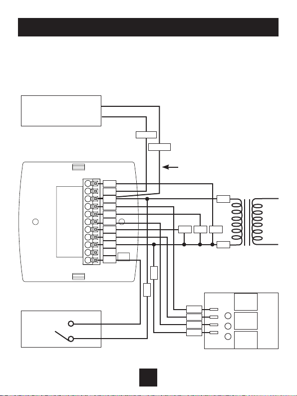
Thermostat
Connect directly to R
terminal on backplate
IMPORTANT NOTE:
If a duct sensor is connected
to this thermostat it is
suggested that the fan be
programmed for continuous
operation (Setup Step #18,
page 19 of the Owner’s
Manual)
Generic relay board
24vac24 volt
water
valves
Dry Contact
Duct Sensor
ACCDSEN
Wiring Diagram
4-Pipe, Low Voltage Valves, Duct
Temperature Sensor & Dry Contact
RS
R
G3
Y1
G
W1
G2
C
H20
CK1
R
H
C
G3
G2
G
COM
R
C
WHITE
BLACK
CH
CL
COM LOW MED HIGH
Y2

4
Installation Instructions
SCALE 1 : 1
Thermostat If 2-pipe with
auxiliary electric heat
24vac24 volt
water
valve
H20 Changeover Sensor
(G100-71520306)
(closes below 60˚,
opens above 75˚)
Wiring Diagram
2-Pipe, Low Voltage Valve, H20 Changeover Sensor
R
G3
Y1
G
W1
G2
C
H20
R
VEH
C
R
C
Generic relay board
G3
G2
G
COM
COM LOW MED HIGH
5
At minimum the first 3 tasks below must be completed to access your
thermostat remotely from a browser. The 4th step is optional (highly
recommended) and only is needed to access your thermostat(s) from a
mobile device.
These steps are:
1. Successful connection to a local Wi-Fi Access Point with internet
access.
2. Confirm receipt of a Skyport generated verification email (this only
occurs once during the Skyport account setup).
3. A 6-digit code obtained from the thermostat is successfully entered
into a Skyport account.
4. Successfully download and install the IEC Skyport app on your mobile
device(s).
Your thermostat operates on the 2.4 Ghz, Wi-Fi b/g/n band.
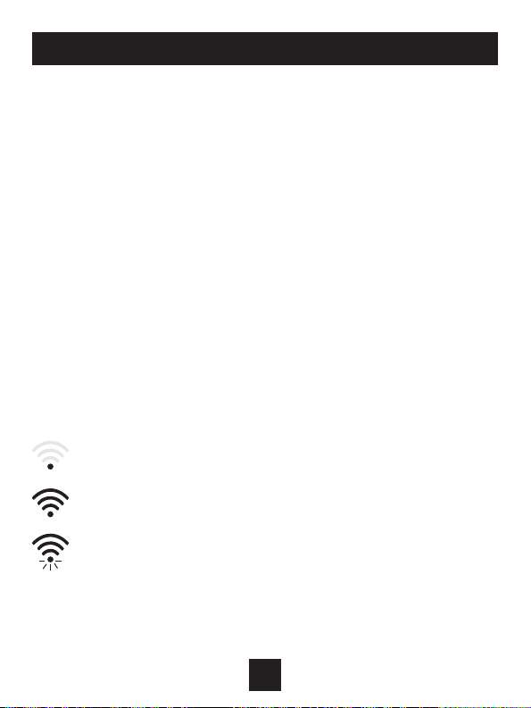
Wi-Fi Symbol Legend
When the only the ‘dot’ of the Wi-Fi symbol appears = not
connected to an access point.
When the full Wi-Fi symbol appears = connected to an
access point.
When the full Wi-Fi symbol appears and the ‘dot’ of the symbol is
flashing = connected to Skyport.
Connect to Wi-Fi Overview
6
Connect to Wi-Fi Overview
Wi-Fi Setup
The IEC Configurator App is needed to configure the Wi-Fi Settings of
this thermostat
• Download the IEC Configurator App
from your mobile device’s App Store.
• Open the IEC Configurator App
- Choose the thermostat by sliding the
thermostat pictures at the top of the apps’ display
to the left until you see a picture of the thermostat.
- Press and hold the FAN button of the thermostat for
approximately 5 seconds to enter Wi-Fi setup screens.
- Press the cooler button to setup Wi-Fi.
- Follow the instructions that appear on the IEC
Configurator App.
Connect to Skyport
Although there is more than one way to create a Skyport account, the
steps below illustrate account creation from a browser. To create a
Skyport account a thermostat must be joined to the account.
If the thermostat is connected to the local Wi-Fi Access Point, but you
do not have a Skyport account, you may create an account and join the
thermostat to the account by doing the following:
1. Open your browser to: http://IEC.skyportcloud.com
2. Select “Create account now”
3. Follow on screen instructions to create an account and add a
thermostat to the Skyport account.
Create Account Now
ICON

7
Connect to Wi-Fi Overview
Join a Thermostat to Skyport
If the thermostat is connected to the local Wi-Fi access point but not yet
joined to an existing Skyport account, you may join the thermostat to the
account by doing the following:
1. Log in to your Skyport account.
2. Select the “Location” you want to add a thermostat into.
3. Select the “Thermostat tab”.
4. Select “+ Add thermostat”. A screen will ‘pop-up’ asking for a
six digit code.
5. Press the FAN button on the thermostat for 5 seconds.
6. Press the Warmer button on the thermostat.
7. A six digit code will appear on the thermostat’s display.
8. Enter the six digit code into your Skyport account.
Wi-Fi Status Screens
Press and hold the FAN button on the thermostat for 5 seconds. When
“Wi-Fi Setup” appears on the display, press the MODE button. Pressing
the up or down button will sequence through the following information:
• AP Name
• AP Signal Strength
• IP Address
• Skyport Status
• API Status
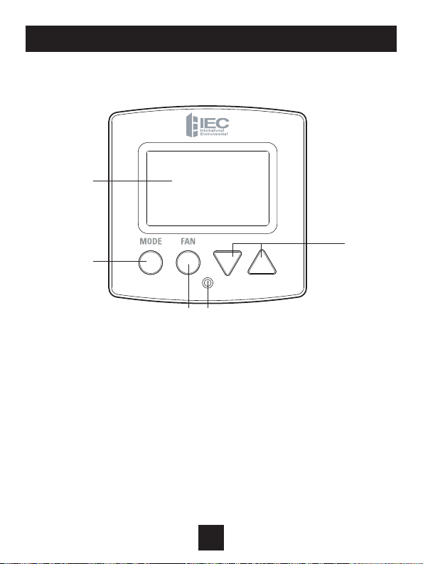
Front Panel
8
1Backlit Display
2Up/Warmer, Down/Cooler Buttons
3Mode Button
4Fan Button
5Heat or Cool Indicator
Heat = Red, Cool = Green
1
3
2
4 5
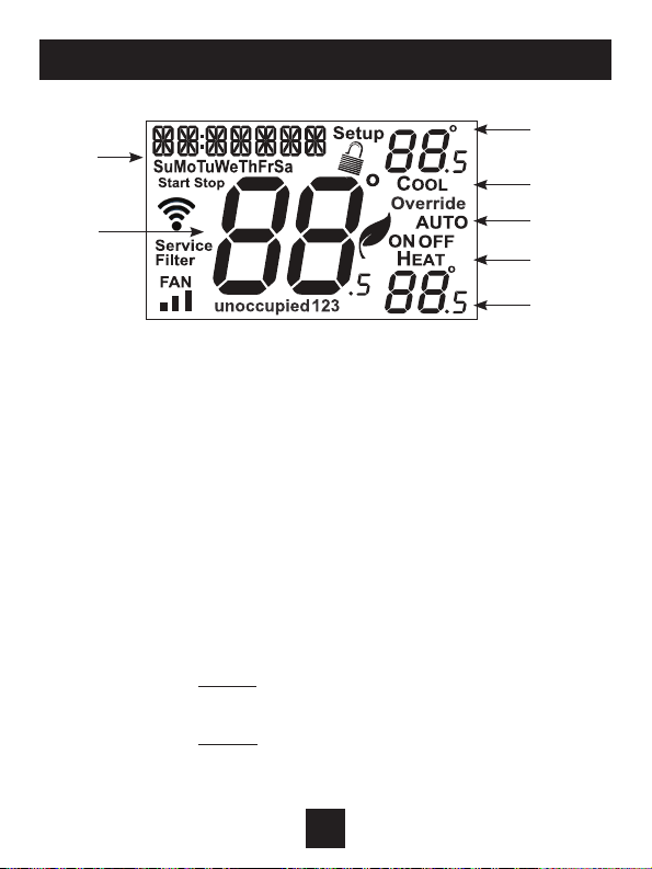
Display
9
1Mode Indicators
Selects the operational mode of the equipment.
HEAT - Indicates the heating mode.
COOL - Indicates the cooling mode.
AUTO - Indicates the system will automatically changeover
between heat and cool modes as the temperature
varies.
OFF - Indicates heating and cooling are turned off.
2 Clock with Day of the Week
Indicates the current time and day. This clock is also used to
program the time period schedules.
3Room Temperature Display
Indicates current room temperature.
4Desired Set Temperature
Indicates desired room temperature(s).
2
3
4
1
1
1
4
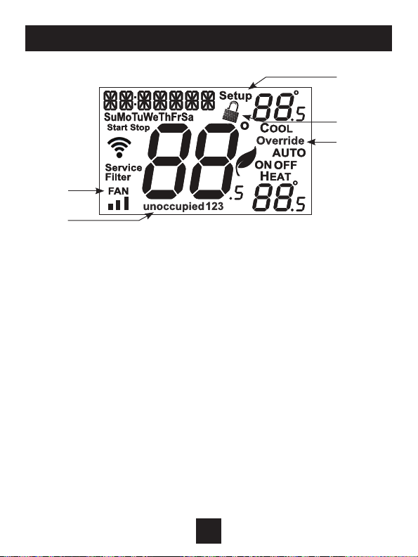
Display
10
5 Occupied and Unoccupied icons
Indicates the part of the time period program.
6 Setup icon
Indicates the thermostat is in the setup mode.
7 Fan icon
When FAN and any fan speed bar is on, the fan is in
manual speed. If the FAN is not on the display, then the
FAN is in Auto mode and will run only when necessary
to heat or cool.
8 Locked icon
Indicates the thermostat’s control buttons have
been locked.
9 Override icon
Indicates OVERRIDE is enabled.
6
9
5
8
7

Basic Operation
11
Selecting Your Desired Temperature (adjusting the setpoints)
Heat or Cool Mode
Using the FAN Button
Auto-Changeover Mode
Pressing the WARMER or COOLER buttons in
Auto mode will adjust both the heat and cool
setpoints simultaneously. To adjust the heat
and cool setpoints individually, choose HEAT
mode to adjust the heat setpoint, and COOL
mode to adjust the cool setpoint, then return
to AUTO mode.
Pressing the UP or DOWN buttons in
Heat or Cool mode will adjust only the
heat or cool set temperature.
Adjust the desired set
temperature with these buttons
Pressing the FAN button will run the fan in low, medium, or high speed
continuously.
If the FAN is not on the display, then the fan is in Auto mode and will run only
when necessary to heat or cool.
NOTE: If the thermostat is placed in the OFF mode, the fan will de-energize.

Using the FAN button for Fan Operation
Note: When the thermostat is placed in OFF with the MODE button the fan
will not operate, unless Setup Step #18 is set to ON (page 19).
Using the FAN button for OVERRIDE OPERATION
Note: Override operation may only be used when the thermostat is run-
ning a time period schedule/program.
Unoccupied Operation
During programmed, unoccupied periods pressing and holding the FAN button for
more than 5 seconds will force the thermostat into occupied 1 settings for 1 to 4
hours (Setup Step #16, page 19). The Override icon will be illuminated during
this time.
If you press and hold the FAN button while the thermostat is currently overriding the
daily schedule, this will reset the timer, returning the thermostat to the correct time
period program for the day.
Occupied Operation
Pressing and holding the FAN button for 5 seconds during a programmed
Occupied time period will not function as override but will enter the wifi
setup section.
Press
FAN
Press
FAN
Press
FAN
Press
FAN
low speed medium speed high speed auto
FAN
Basic Operation
12
How to Change Settings in the Setup Screens
To enter the setup screens, press the MODE button, and
simultaneously press FAN button for 5 seconds. Release the buttons
when you see “Setup” on the display. Use the WARMER or COOLER
buttons to adjust the value of your selection. Press MODE to advance
to the next setup step. Press MODE and FAN together again to leave
the setup screens.
User Setup
13
FANMODE
press together for
5 seconds
TO ENTER MENUS BUTTON PRESS
Setup Steps MODE & FAN for 5 seconds
Time Schedule MODE & UP for 2 seconds
Emergency Heat UP & FAN for 2 seconds
Lockout Buttons MODE, UP & DOWN for 2 seconds
Calibration MODE & DOWN for 2 seconds, then MODE
Wireless Setup FAN for 5 seconds unless running
time period program
Table for button
presses that are
required for
entering various
menus

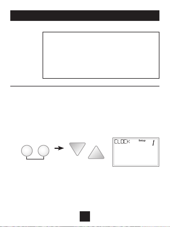
Setting the Clock and Day (setup steps 1 & 2)
When your thermostat is connected to Skyport Cloud Services, the time
and day of the week are controlled by Skyport. There is no local adjust-
ment, Skyport also adjusts the time for Daylight Savings Time as well.
To set the time and day when not connected to Skyport; enter the setup
screens by pressing the MODE button and simultaneously pressing the
FAN button for 5 seconds.
Setup step 1 adjusts the clock.
User Setup
14
Use the Warmer/Up or Cooler/Down buttons
to adjust the time.
Press the MODE button to advance to step 2.
Select the day of the week using the Warmer/
Up or Cooler/Down buttons.
Leave the setup screens by again pressing the MODE
button and simultaneously pressing the FAN button
for 5 seconds.
Show Clock (setup step 3)
This setup step will allow for removal of the
clock and day of the week from the display.
OFF removes the time and day from the
display.

Backlight (setup steps 5-8)
Backlight (setup step 5)
OFF - Backlight turns on only with
a button press and turns off after
8 seconds.
ON - Backlight is on continuously.
Night Dimmer (setup step 6)
Selecting ON allows for turning off the
backlight of the display during specific
times of the day, usually at night.
Night Dimmer StartTime (setup step 7)
12:00 am to 12:00 am
Night Dimmer StopTime (setup step 8)
12:00 am to 12:00 am
User Setup: Backlight Operation
15
Programmable (setup step 4)
When the very simplest operation is desired,
this thermostat may be configured to be non-
programmable, with or without Auto-Changeover.
If “NO” is selected, the thermostat will lockout
the Program On screen; only the Off, Heat, Cool
and Auto screens may be accessed by pressing
the MODE button.
Select “YES” if you would like your thermostat to be
programmable, then the Program mode will be
accessible through the use of the MODE button.
This manual suits for next models
1
Table of contents
Other IEC Thermostat manuals


