manuals.online logo
Brands
  1. Home
  2. •
  3. Brands
  4. •
  5. IEI Technology
  6. •
  7. Motherboard
  8. •
  9. IEI Technology IMBA-H110 User manual

IEI Technology IMBA-H110 User manual

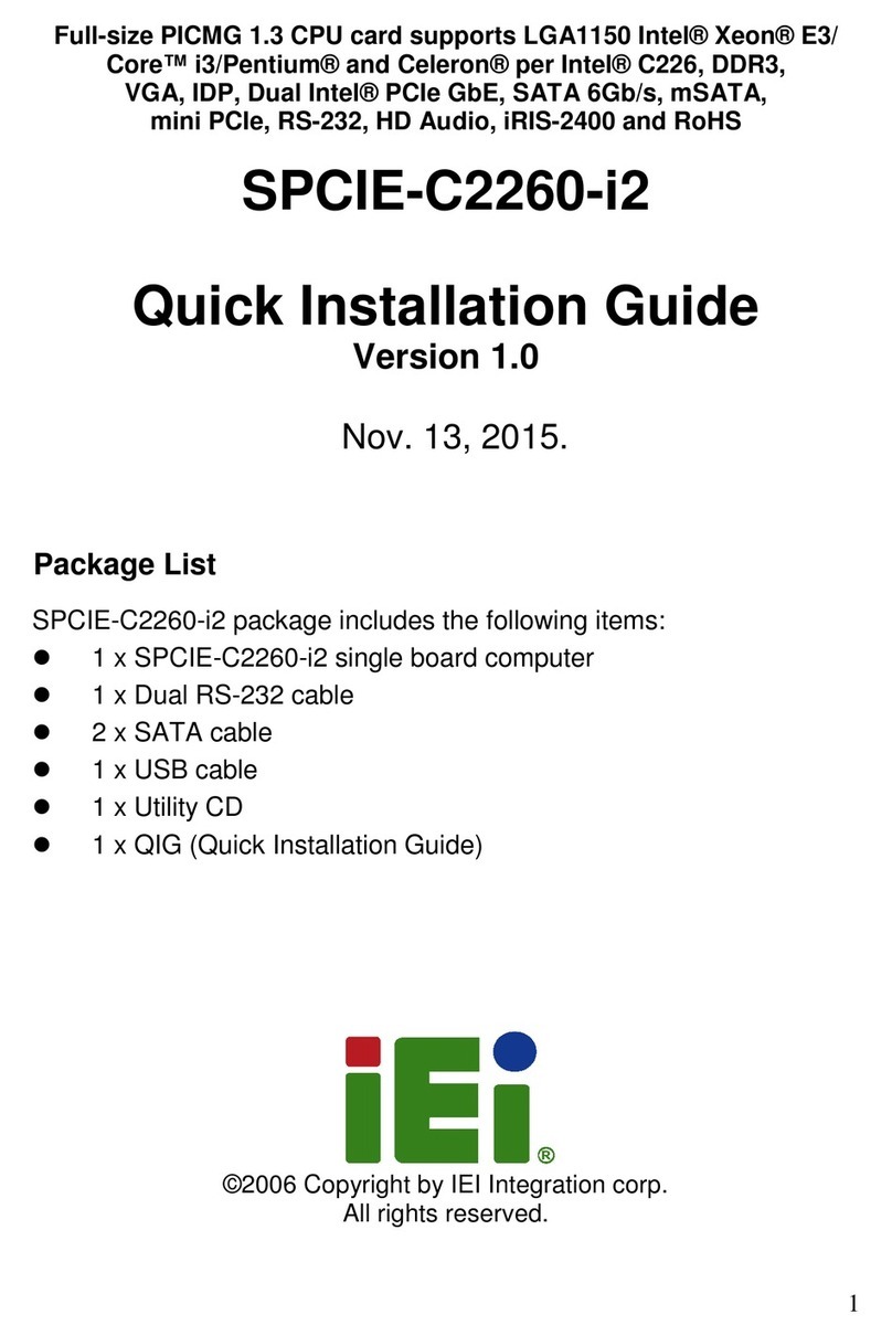
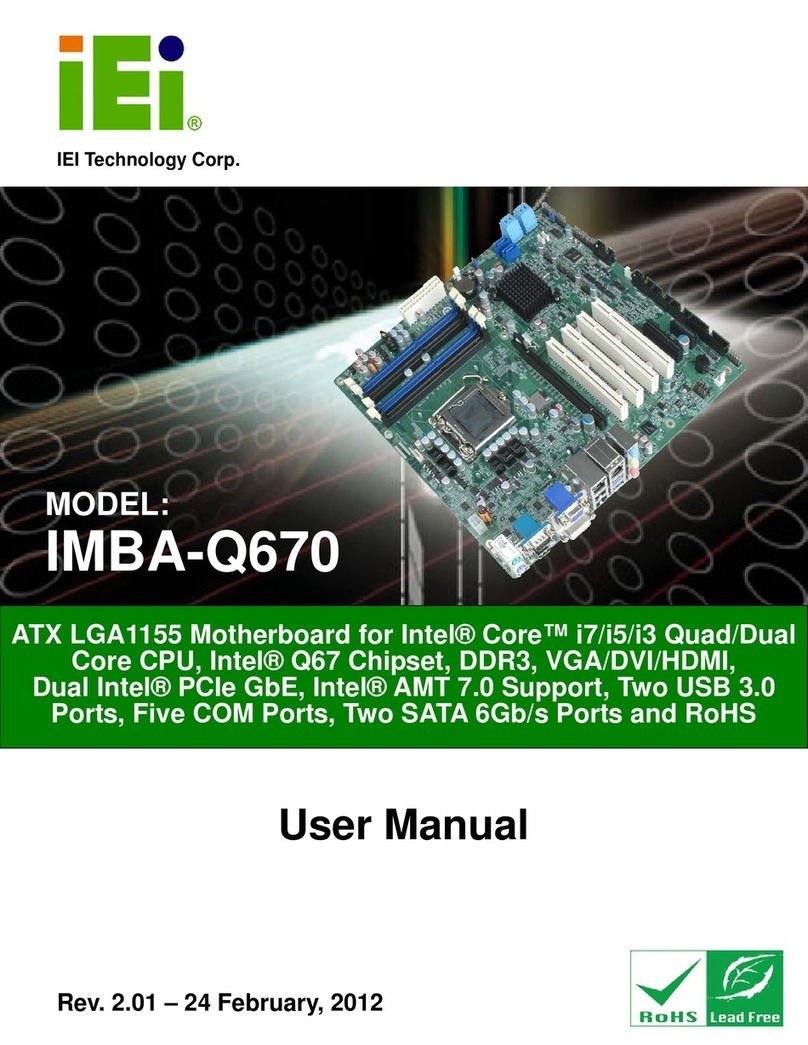
IMBA-H110 ATX Motherboard
Page i
User Manual
MODEL:
IMBA-H110
ATX Motherboard Supports 6th Generation LGA1151
Intel® Core™ i7/i5/i3, Pentium® or Celeron® CPU,
Intel® H110 Chipset, DDR4, HDMI, DVI-I, iDP, SATA 6Gb/s,
USB 3.2 Gen 1, Dual Intel® GbE LAN, HD Audio and RoHS
Rev. 1.01 – June 30, 2020
IMBA-H110 ATX Motherboard
Page ii
Revision
Date Version Changes
June 30, 2020 1.01 Modified the available configuration options of the DVMT
Pre-Allocated BIOS item.
October 31, 2016 1.00 Initial release
IMBA-H110 ATX Motherboard
Page iii
Copyright
COPYRIGHT NOTICE
The information in this document is subject to change without prior notice in order to
improve reliability, design and function and does not represent a commitment on the part
of the manufacturer.
In no event will the manufacturer be liable for direct, indirect, special, incidental, or
consequential damages arising out of the use or inability to use the product or
documentation, even if advised of the possibility of such damages.
This document contains proprietary information protected by copyright. All rights are
reserved. No part of this manual may be reproduced by any mechanical, electronic, or
other means in any form without prior written permission of the manufacturer.
TRADEMARKS
All registered trademarks and product names mentioned herein are used for identification
purposes only and may be trademarks and/or registered trademarks of their respective
owners.
IMBA-H110 ATX Motherboard
Page iv
Manual Conventions
WARNING
Warnings appear where overlooked details may cause damage to the
equipment or result in personal injury. Warnings should be taken
seriously.
CAUTION
Cautionary messages should be heeded to help reduce the chance of
losing data or damaging the product.
NOTE
These messages inform the reader of essential but non-critical
information. These messages should be read carefully as any directions
or instructions contained therein can help avoid making mistakes.
IMBA-H110 ATX Motherboard
Page v
Table of Contents
1 INTRODUCTION.......................................................................................................... 1
1.1 INTRODUCTION........................................................................................................... 2
1.2 FEATURES................................................................................................................... 3
1.3 CONNECTORS ............................................................................................................. 4
1.4 DIMENSIONS............................................................................................................... 5
1.5 DATA FLOW ................................................................................................................ 6
1.6 TECHNICAL SPECIFICATIONS ...................................................................................... 7
2 PACKING LIST ........................................................................................................... 10
2.1 ANTI-S TAT I C PRECAUTIONS .......................................................................................11
2.2 UNPACKING PRECAUTIONS........................................................................................11
2.3 PACKING LIST........................................................................................................... 12
2.4 OPTIONAL ITEMS ...................................................................................................... 13
3 CONNECTORS ........................................................................................................... 15
3.1 PERIPHERAL INTERFACE CONNECTORS..................................................................... 16
3.1.1 IMBA-H110 Layout .......................................................................................... 16
3.1.2 Peripheral Interface Connectors ..................................................................... 17
3.1.3 External Interface Panel Connectors............................................................... 18
3.2 INTERNAL PERIPHERAL CONNECTORS ...................................................................... 19
3.2.1 +12V Power Connector ................................................................................... 19
3.2.2 Additional Power Connector ........................................................................... 19
3.2.3 ATX Power Connector ..................................................................................... 20
3.2.4 Battery Connector............................................................................................ 22
3.2.5 Chassis Intrusion Connector............................................................................ 23
3.2.6 CRT FW Update Connector............................................................................. 24
3.2.7 DDR4 DIMM Slots........................................................................................... 24
3.2.8 Digital I/O Connector ...................................................................................... 25
3.2.9 EC Debug Connector....................................................................................... 26
3.2.10 Fan Connector (CPU).................................................................................... 27
IMBA-H110 ATX Motherboard
Page vi
3.2.11 Fan Connectors (System) ............................................................................... 28
3.2.12 Front Panel Audio Connector........................................................................ 29
3.2.13 Front Panel Connector .................................................................................. 30
3.2.14 I2CConnector ................................................................................................ 31
3.2.15 Internal DisplayPort Connector .................................................................... 32
3.2.16 Keyboard and Mouse Connector ................................................................... 33
3.2.17 LAN LED Connectors .................................................................................... 34
3.2.18 Parallel Port Connector ................................................................................ 35
3.2.19 PCI Slots ........................................................................................................ 36
3.2.20 PCI Express x16 Slot...................................................................................... 37
3.2.21 PCIe Mini Slot................................................................................................ 37
3.2.22 Power Button ................................................................................................. 39
3.2.23 RS-232 Serial Port Connector ....................................................................... 40
3.2.24 RS-232/422/485 Serial Port Connector ......................................................... 41
3.2.25 SATA 6Gb/s Drive Connector ........................................................................ 42
3.2.26 SMBus Connector .......................................................................................... 44
3.2.27 SPI Flash Connector...................................................................................... 45
3.2.28 SPI Flash Connector, EC ............................................................................... 46
3.2.29 TPM Connector.............................................................................................. 47
3.2.30 USB 2.0 Connector (Type A).......................................................................... 48
3.2.31 USB 2.0 Connector ........................................................................................ 49
3.3 EXTERNAL PERIPHERAL INTERFACE CONNECTOR PANEL ......................................... 50
3.3.1 Audio Connector .............................................................................................. 50
3.3.2 DVI-I and HDMI Connectors .......................................................................... 51
3.3.3 Ethernet and USB 3.2 Gen 1 Connectors ........................................................ 53
3.3.4 Keyboard/Mouse and USB 2.0 Connectors ..................................................... 54
3.3.5 Serial Port Connectors .................................................................................... 55
4 INSTALLATION ......................................................................................................... 56
4.1 ANTI-S TAT I C PRECAUTIONS ...................................................................................... 57
4.2 INSTALLATION CONSIDERATIONS.............................................................................. 57
4.3 SOCKET LGA1151 CPU INSTALLATION ................................................................... 59
4.4 SOCKET LGA1151 COOLING KIT INSTALLATION ..................................................... 62
4.5 DIMM INSTALLATION .............................................................................................. 64
4.6 FULL-SIZE PCIE MINI CARD INSTALLATION ............................................................. 65
IMBA-H110 ATX Motherboard
Page vii
4.7 HALF-SIZE PCIE MINI CARD INSTALLATION............................................................. 66
4.8 SYSTEM CONFIGURATION......................................................................................... 68
4.8.1 AT/ATX Power Mode Setting ........................................................................... 68
4.8.2 Clear CMOS Button......................................................................................... 69
4.8.3 DVI/CRT Selection Switch ............................................................................... 69
4.8.4 Flash Descriptor Security Override................................................................. 70
4.8.5 mSATA Setup Jumper ....................................................................................... 71
4.8.6 USB Power Selection ....................................................................................... 72
4.9 INTERNAL PERIPHERAL DEVICE CONNECTIONS........................................................ 72
4.9.1 SATA Drive Connection ................................................................................... 72
4.10 ADDING USB 3.2 DRIVERS TO A WINDOWS 7INSTALLATION IMAGE ...................... 74
4.11 AVAILABLE DRIVERS .............................................................................................. 76
4.11.1 Driver Download............................................................................................ 77
5 BIOS .............................................................................................................................. 79
5.1 INTRODUCTION......................................................................................................... 80
5.1.1 Starting Setup................................................................................................... 80
5.1.2 Using Setup ...................................................................................................... 80
5.1.3 Getting Help..................................................................................................... 81
5.1.4 Unable to Reboot after Configuration Changes .............................................. 81
5.1.5 BIOS Menu Bar................................................................................................ 81
5.2 MAIN........................................................................................................................ 82
5.3 ADVANCED ............................................................................................................... 83
5.3.1 Trusted Computing........................................................................................... 84
5.3.2 ACPI Settings ................................................................................................... 85
5.3.3 Super IO Configuration ................................................................................... 86
5.3.3.1 Serial Port 1 ~ 5 Configuration................................................................. 87
5.3.3.2 Serial Port 1 Configuration ....................................................................... 87
5.3.3.3 Serial Port 2 Configuration ....................................................................... 88
5.3.3.4 Serial Port 3 Configuration ....................................................................... 88
5.3.3.5 Parallel Port Configuration ....................................................................... 91
5.3.4 iWDD H/W Monitor......................................................................................... 92
5.3.4.1 Smart Fan Mode Configuration ................................................................ 93
5.3.5 RTC Wake Settings ........................................................................................... 94
5.3.6 Serial Port Console Redirection ...................................................................... 96
IMBA-H110 ATX Motherboard
Page viii
5.3.6.1 Legacy Console Redirection Settings ....................................................... 98
5.3.7 CPU Configuration .......................................................................................... 99
5.3.8 SATA Configuration........................................................................................ 101
5.3.9 NVMe Configuration...................................................................................... 102
5.3.10 USB Configuration....................................................................................... 103
5.3.11 iEi Feature.................................................................................................... 104
5.4 CHIPSET ................................................................................................................. 105
5.4.1 System Agent (SA) Configuration .................................................................. 106
5.4.1.1 Graphics Configuration........................................................................... 107
5.4.1.2 PEG Port Configuration.......................................................................... 109
5.4.1.3 Memory Configuration ............................................................................110
5.4.2 PCH-IO Configuration ................................................................................... 111
5.4.2.1 PCI Express Configuration ......................................................................113
5.4.2.2 HD Audio Configuration..........................................................................115
5.5 SECURITY ................................................................................................................116
5.6 BOOT.......................................................................................................................117
5.7 SAV E &EXIT ...........................................................................................................119
A REGULATORY COMPLIANCE ............................................................................ 120
B PRODUCT DISPOSAL ............................................................................................ 122
C BIOS OPTIONS ........................................................................................................ 124
D DIGITAL I/O INTERFACE ..................................................................................... 128
D.1 INTRODUCTION...................................................................................................... 129
D.2 ASSEMBLY LANGUAGE SAMPLE 1.......................................................................... 130
D.3 ASSEMBLY LANGUAGE SAMPLE 2.......................................................................... 130
E WATCHDOG TIMER............................................................................................... 131
F ERROR BEEP CODE ............................................................................................... 134
F.1 PEI BEEP CODES .................................................................................................... 135
F.2 DXE BEEP CODES .................................................................................................. 135
G HAZARDOUS MATERIALS DISCLOSURE ....................................................... 136
G.1 ROHS II DIRECTIVE (2015/863/EU) ..................................................................... 137
G.2 CHINA ROHS......................................................................................................... 138
IMBA-H110 ATX Motherboard
Page ix
List of Figures
Figure 1-1: IMBA-H110 ...................................................................................................................2
Figure 1-2: Connectors ..................................................................................................................4
Figure 1-3: IMBA-H110 Dimensions (mm)....................................................................................5
Figure 1-4: Data Flow Diagram......................................................................................................6
Figure 3-1: Peripheral Interface Connectors .............................................................................16
Figure 3-2: +12V Power Connector Pinout Location ................................................................19
Figure 3-3: Additional Power Connector Location....................................................................20
Figure 3-4: ATX Power Connector Location ..............................................................................21
Figure 3-5: Battery Connector Location.....................................................................................22
Figure 3-6: Chassis Intrusion Connector Location...................................................................23
Figure 3-7: CRT FW Update Connector Location......................................................................24
Figure 3-8: DDR4 DIMM Slot Locations......................................................................................25
Figure 3-9: Digital I/O Connector Location ................................................................................25
Figure 3-10: EC Debug Connector Location..............................................................................26
Figure 3-11: CPU Fan Connector Location ................................................................................27
Figure 3-12: System Fan Connector Locations.........................................................................28
Figure 3-13: Front Panel Audio Connector Location ................................................................29
Figure 3-14: Front Panel Connector Location ...........................................................................30
Figure 3-15: I2C Connector Location ..........................................................................................31
Figure 3-16: Internal DisplayPort Connector Location .............................................................32
Figure 3-17: Keyboard and Mouse Connector Location...........................................................33
Figure 3-18: LAN1 LED Connector Location .............................................................................34
Figure 3-19: Parallel Port Connector Location ..........................................................................35
Figure 3-20: PCI Slot Locations ..................................................................................................36
Figure 3-21: PCIe x16 Slot Location ...........................................................................................37
Figure 3-22: PCIe Mini Slot Location ..........................................................................................38
Figure 3-23: Power Button Location...........................................................................................39
Figure 3-24: RS-232 Serial Port Connector Locations..............................................................40
Figure 3-25: RS-232/422/485 Connector Location.....................................................................41
Figure 3-26: SATA 6Gb/s Drive Connector Location ................................................................43
IMBA-H110 ATX Motherboard
Page x
Figure 3-27: SMBus Connector Location...................................................................................44
Figure 3-28: SPI Flash Connector Location...............................................................................45
Figure 3-29: SPI EC Flash Connector Location.........................................................................46
Figure 3-30: TPM Connector Location........................................................................................47
Figure 3-31: USB 2.0 Connector (Type A) Pinout Location......................................................48
Figure 3-32: USB 2.0 Connector Pinout Locations ...................................................................49
Figure 3-33: External Peripheral Interface Connector ..............................................................50
Figure 3-34: Audio Connector .....................................................................................................51
Figure 3-35: DVI-I Connector .......................................................................................................52
Figure 3-36: LAN Connector........................................................................................................53
Figure 3-37: Serial Port Connector Pinouts...............................................................................55
Figure 4-1: Disengage the CPU Socket Load Lever..................................................................59
Figure 4-2: Remove Protective Cover.........................................................................................60
Figure 4-3: Insert the Socket LGA1151 CPU..............................................................................61
Figure 4-4: Close the Socket LGA1151 ......................................................................................61
Figure 4-5: Cooling Kit Support Bracket....................................................................................63
Figure 4-6: DIMM Installation.......................................................................................................64
Figure 4-7: Removing the Retention Screw ...............................................................................65
Figure 4-8: Inserting the Full-size PCIe Mini Card into the Slot at an Angle ..........................65
Figure 4-9: Securing the Full-size PCIe Mini Card ....................................................................66
Figure 4-10: Installing the Standoff ............................................................................................67
Figure 4-11: Inserting the Half-size PCIe Mini Card into the Slot at an Angle........................67
Figure 4-12: Securing the Half-size PCIe Mini Card ..................................................................68
Figure 4-13: AT/ATX Power Mode Switch Location ..................................................................68
Figure 4-14: Clear CMOS Button Location.................................................................................69
Figure 4-15: DVI/CRT Selection Switch Location ......................................................................70
Figure 4-16: Flash Descriptor Security Override Jumper Location ........................................70
Figure 4-17: mSATA Setup Jumper Location ............................................................................71
Figure 4-18: SATA Drive Cable Connection...............................................................................73
Figure 4-19: SATA Power Drive Connection..............................................................................74
Figure 4-20: Windows 7 USB 3.0 Creator Utility........................................................................75
Figure 4-21: Update Process is Complete .................................................................................76
Figure 4-22: IEI Resource Download Center..............................................................................76
IMBA-H110 ATX Motherboard
Page xi
List of Tables
Table 1-1: IMBA-H110 Specifications ...........................................................................................9
Table 2-1: Packing List.................................................................................................................12
Table 2-2: Optional Items.............................................................................................................14
Table 3-1: Peripheral Interface Connectors ...............................................................................18
Table 3-2: Rear Panel Connectors ..............................................................................................18
Table 3-3: +12V Power Connector Pinouts ................................................................................19
Table 3-4: Additional Power Connector Pinouts .......................................................................20
Table 3-5: ATX Power Connector Pinouts .................................................................................21
Table 3-6: Chassis Intrusion Connector Pinouts ......................................................................23
Table 3-7: CRT FW Update Connector Pinouts .........................................................................24
Table 3-8: Digital I/O Connector Pinouts....................................................................................26
Table 3-9: EC Debug Connector Pinouts ...................................................................................27
Table 3-10: CPU Fan Connector Pinouts ...................................................................................27
Table 3-11: System Fan Connector Pinouts ..............................................................................28
Table 3-12: Front Panel Audio Connector Pinouts ...................................................................29
Table 3-13: Front Panel Connector Pinouts...............................................................................30
Table 3-14: I2C Connector Pinouts..............................................................................................31
Table 3-15: Internal DisplayPort Connector Pinouts ................................................................32
Table 3-16: Keyboard and Mouse Connector Pinouts..............................................................33
Table 3-17: LAN LED Connector Pinouts...................................................................................34
Table 3-18: Parallel Port Connector Pinouts .............................................................................35
Table 3-19: PCIe Mini Slot Pinouts..............................................................................................39
Table 3-20: RS-232 Serial Port Connector Pinouts ...................................................................40
Table 3-21: RS-232/422/485 Connector Pinouts ........................................................................41
Table 3-22: DB-9 RS-232/422/485 Pinouts..................................................................................42
Table 3-23: SATA 6Gb/s Drive Connector Pinouts....................................................................43
Table 3-24: SMBus Connector Pinouts ......................................................................................44
Table 3-25: SPI Flash Connector Pinouts ..................................................................................45
Table 3-26: SPI EC Flash Connector Pinouts ............................................................................46
Table 3-27: TPM Connector Pinouts...........................................................................................47
IMBA-H110 ATX Motherboard
Page xii
Table 3-28: USB 2.0 Connector (Type A) Pinouts .....................................................................48
Table 3-29: USB 2.0 Connector Pinouts.....................................................................................49
Table 3-30: DVI-I Connector Pinouts ..........................................................................................52
Table 3-31: HDMI Connector Pinouts .........................................................................................52
Table 3-32: USB 3.2 Gen 1 Port Pinouts ....................................................................................53
Table 3-33: LAN Pinouts ..............................................................................................................53
Table 3-34: USB 2.0 Port Pinouts................................................................................................54
Table 3-35: PS/2 Connector Pinouts...........................................................................................54
Table 3-36: Serial Port Connector Pinouts ................................................................................55
Table 4-1: AT/ATX Power Mode Switch Settings.......................................................................69
Table 4-2: DVI/CRT Selection Switch Settings ..........................................................................69
Table 4-3: Flash Descriptor Security Override Jumper Settings.............................................70
Table 4-4: mSATA Setup Jumper Settings.................................................................................71
Table 4-5: BIOS Options and Configured USB Ports................................................................72
Table 4-6: USB Power Source Setup ..........................................................................................72
Table 5-1: BIOS Navigation Keys ................................................................................................81
Table 5-2: BIOS Options and Configured USB Ports..............................................................112
IMBA-H110 ATX Motherboard
Page xiii
BIOS Menus
BIOS Menu 1: Main .......................................................................................................................82
BIOS Menu 2: Advanced ..............................................................................................................83
BIOS Menu 3: Trusted Computing ..............................................................................................84
BIOS Menu 4: ACPI Configuration ..............................................................................................85
BIOS Menu 5: Super IO Configuration........................................................................................86
BIOS Menu 6: Serial Port 1 ~ 5 Configuration Menu.................................................................87
BIOS Menu 7: Parallel Port Configuration Menu .......................................................................91
BIOS Menu 8: iWDD H/W Monitor ...............................................................................................92
BIOS Menu 9: Smart Fan Mode Configuration ..........................................................................93
BIOS Menu 10: RTC Wake Settings ............................................................................................95
BIOS Menu 11: Serial Port Console Redirection .......................................................................96
BIOS Menu 12: Legacy Console Redirection Settings .............................................................98
BIOS Menu 13: CPU Configuration .............................................................................................99
BIOS Menu 14: SATA Configuration .........................................................................................101
BIOS Menu 15: NVMe Configuration.........................................................................................102
BIOS Menu 16: USB Configuration ...........................................................................................103
BIOS Menu 17: iEi Feature.........................................................................................................104
BIOS Menu 18: Chipset ..............................................................................................................105
BIOS Menu 19: System Agent (SA) Configuration ..................................................................106
BIOS Menu 20: Graphics Configuration...................................................................................107
BIOS Menu 21: PEG Port Configuration...................................................................................109
BIOS Menu 22: Memory Configuration.....................................................................................110
BIOS Menu 23: PCH-IO Configuration......................................................................................111
BIOS Menu 24: PCI Express Configuration .............................................................................113
BIOS Menu 25: MPCIE1 Slot ......................................................................................................113
BIOS Menu 26: HD Audio Configuration ..................................................................................115
BIOS Menu 27: Security .............................................................................................................116
BIOS Menu 28: Boot ...................................................................................................................117
BIOS Menu 29: Save & Exit........................................................................................................119
IMBA-H110 ATX Motherboard
Page 1
Chapter
1
1 Introduction
IMBA-H110 ATX Motherboard
Page 2
1.1 Introduction
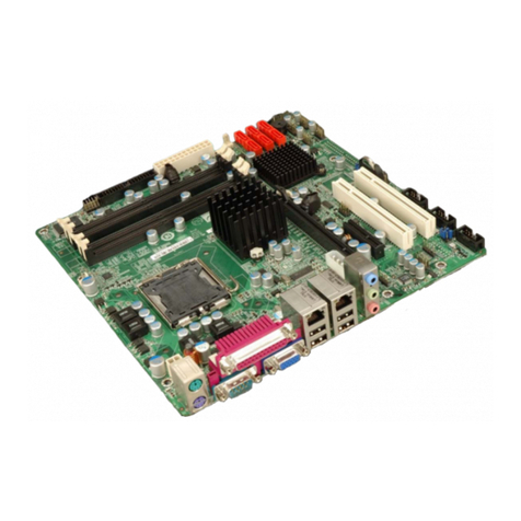
Figure 1-1: IMBA-H110
The IMBA-H110 is an ATX motherboard. It accepts a Socket LGA1151 Intel® Core™
i7/i5/i3, Pentium® or Celeron® processor and supports two 288-pin 2133 MHz
dual-channel DDR4 DIMMs up to 64 GB.
The IMBA-H110 provides two GbE interfaces through the Intel® I219LM and the Intel®
I211 PCIe controllers. The integrated Intel® H110 chipset supports four SATA 6Gb/s
drives. In addition, the IMBA-H110 includes HDMI, DVI-I and iDP interfaces for dual
independent display.
Expansion and I/O include six PCI slots, one PCIe x16 slot, one PCIe Mini slot with
mSATA support, four USB 3.2 Gen 1 (5Gb/s) and two USB 2.0 on the rear panel, two
USB 2.0 by pin headers, one USB 2.0 by internal Type A connector, four RS-232 and one
RS-232/422/485. High Definition Audio (HDA) support ensures HDA devices can be
easily implemented on the IMBA-H110.
IMBA-H110 ATX Motherboard
Page 3
1.2 Features
Some of the IMBA-H110 motherboard features are listed below:
ATX form factor
6th generation LGA1151 Intel® Core™ i7/i5/i3, Pentium® or Celeron®
processor supported
Intel® H110 chipset
Two 288-pin 2133 MHz dual-channel unbuffered DDR4 DIMMs support up to
64 GB
Two Intel® PCIe GbE connectors
Dual independent display by HDMI, DVI-I or iDP interfaces
SATA 6Gb/s and USB 3.2 Gen 1 (5Gb/s) supported
One PCIe Mini slot with mSATA support
One PCIe x16 slot
Six PCI slots
Five COM ports (four RS-232 and one RS-232/422/485)
TPM V2.0 hardware security function supported by TPM module
High Definition Audio
RoHS compliant
IMBA-H110 ATX Motherboard
Page 4
1.3 Connectors
The connectors on the IMBA-H110 are shown in the figure below.
Figure 1-2: Connectors
IMBA-H110 ATX Motherboard
Page 5
1.4 Dimensions
The main dimensions of the IMBA-H110 are shown in the diagram below.
Figure 1-3: IMBA-H110 Dimensions (mm)
IMBA-H110 ATX Motherboard
Page 6
1.5 Data Flow
Figure 1-4 shows the data flow between the system chipset, the CPU and other
components installed on the motherboard.
Figure 1-4: Data Flow Diagram

Other manuals for IMBA-H110

2

Other IEI Technology Motherboard manuals

IEI Technology IMBA-C2160-R10 User manual

IEI Technology

IEI Technology IMBA-C2160-R10 User manual

IEI Technology WAFER-LX-800-R12 User manual

IEI Technology

IEI Technology WAFER-LX-800-R12 User manual

IEI Technology KINO-945GSE3 User manual

IEI Technology

IEI Technology KINO-945GSE3 User manual

IEI Technology NANO-BT Series User manual

IEI Technology

IEI Technology NANO-BT Series User manual

IEI Technology IMBA-9454 User manual

IEI Technology

IEI Technology IMBA-9454 User manual

IEI Technology IOWA-8522 User manual

IEI Technology

IEI Technology IOWA-8522 User manual

IEI Technology IMBA-X9654 User manual

IEI Technology

IEI Technology IMBA-X9654 User manual

IEI Technology IMBA-9454 User manual

IEI Technology

IEI Technology IMBA-9454 User manual

IEI Technology NANO-HM651 User manual

IEI Technology

IEI Technology NANO-HM651 User manual

IEI Technology KINO-G45A User manual

IEI Technology

IEI Technology KINO-G45A User manual

IEI Technology NANO-AL User manual

IEI Technology

IEI Technology NANO-AL User manual

IEI Technology WAFER-LX3 User manual

IEI Technology

IEI Technology WAFER-LX3 User manual

IEI Technology WAFER-LX2-800 User manual

IEI Technology

IEI Technology WAFER-LX2-800 User manual

IEI Technology KINO-ATOM User manual

IEI Technology

IEI Technology KINO-ATOM User manual

IEI Technology IMBA-H110 User manual

IEI Technology

IEI Technology IMBA-H110 User manual

IEI Technology KINO-AQ670 User manual

IEI Technology

IEI Technology KINO-AQ670 User manual

IEI Technology KINO-9653 User manual

IEI Technology

IEI Technology KINO-9653 User manual

IEI Technology KINO-945GSE User manual

IEI Technology

IEI Technology KINO-945GSE User manual

IEI Technology PCIE-Q670-R20 User manual

IEI Technology

IEI Technology PCIE-Q670-R20 User manual

IEI Technology PCISA-6770-RS User manual

IEI Technology

IEI Technology PCISA-6770-RS User manual

IEI Technology NANO-8522 User manual

IEI Technology

IEI Technology NANO-8522 User manual

IEI Technology eKINO-BT User manual

IEI Technology

IEI Technology eKINO-BT User manual

IEI Technology PM-945GSE-N270 User manual

IEI Technology

IEI Technology PM-945GSE-N270 User manual

IEI Technology WSB-G41A User manual

IEI Technology

IEI Technology WSB-G41A User manual

Popular Motherboard manuals by other brands

Motorola MVME3100 Programmer's guide

Motorola

Motorola MVME3100 Programmer's guide

Embest SBC8018 user manual

Embest

Embest SBC8018 user manual

mikroElektronika Shake2Wake click quick start guide

mikroElektronika

mikroElektronika Shake2Wake click quick start guide

Albatron PX845EV1 Series user manual

Albatron

Albatron PX845EV1 Series user manual

Jorjin MM5D91E00 user guide

Jorjin

Jorjin MM5D91E00 user guide

ASROCK FM2A55 Pro user manual

ASROCK

ASROCK FM2A55 Pro user manual

Grasslin QEG-1 operating manual

Grasslin

Grasslin QEG-1 operating manual

DIGITAL-LOGIC Microspace MSB900L user manual

DIGITAL-LOGIC

DIGITAL-LOGIC Microspace MSB900L user manual

SOYO SY-P4VSA quick start guide

SOYO

SOYO SY-P4VSA quick start guide

ASROCK Fatal1ty Z97X Killer Series user manual

ASROCK

ASROCK Fatal1ty Z97X Killer Series user manual

Advantech ASMB-585 user manual

Advantech

Advantech ASMB-585 user manual

mikroElektronika MultiMedia Board manual

mikroElektronika

mikroElektronika MultiMedia Board manual

ASROCK ALIVENF5-VST user manual

ASROCK

ASROCK ALIVENF5-VST user manual

Supermicro Supero X7DBU user manual

Supermicro

Supermicro Supero X7DBU user manual

National Semiconductor ADC10DV200 user guide

National Semiconductor

National Semiconductor ADC10DV200 user guide

Asus Rampage II GENE - Republic of Gamers... user guide

Asus

Asus Rampage II GENE - Republic of Gamers... user guide

Asus M5A88-M user manual

Asus

Asus M5A88-M user manual

Gigabyte GA-X58A-UD3R user manual

Gigabyte

Gigabyte GA-X58A-UD3R user manual

manuals.online logo
manuals.online logoBrands
  • About & Mission
  • Contact us
  • Privacy Policy
  • Terms and Conditions

Copyright 2025 Manuals.Online. All Rights Reserved.