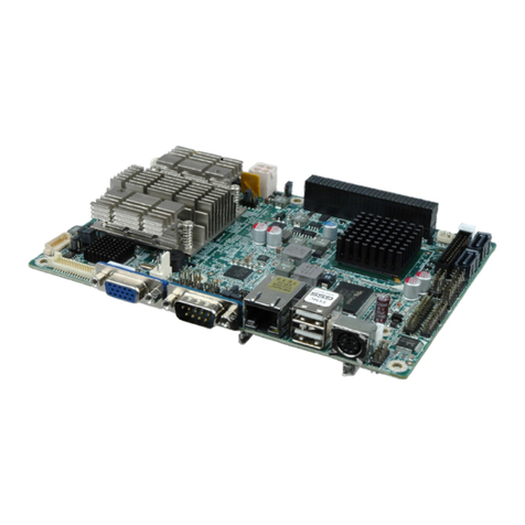
NANO-QM57A EPIC SBC
Page IX
Figure 4-12: Connect Power Cable to Power Supply................................................................46
Figure 4-13: Audio Kit Cable Connection ..................................................................................47
Figure 4-14: Single RS-232 Cable Installation ...........................................................................48
Figure 4-15: DVI Connector .........................................................................................................50
Figure 4-16: LAN Connection......................................................................................................51
Figure 4-17: USB Connector........................................................................................................52
Figure 4-18: VGA Connector .......................................................................................................53
Figure 4-19: Introduction Screen................................................................................................54
Figure 4-20: Available Drivers.....................................................................................................55
Figure A-1: Intel® Active Management Technology Status Dialog.........................................88
Figure A-2: Intel® Current ME Password...................................................................................89
Figure A-3: Intel® ME New Password.........................................................................................90
Figure A-4: Intel® AMT Configuration........................................................................................90
Figure A-5: Select KVM Configuration .......................................................................................91
Figure A-6: KVM Configuration...................................................................................................91
Figure A-7: KVM User Opt-in.......................................................................................................92
Figure A-8: Exit.............................................................................................................................92
Figure C-1: Recovery Tool Setup Menu .................................................................................. 102
Figure C-2: Command Mode..................................................................................................... 102
Figure C-3: Partition Creation Commands.............................................................................. 103
Figure C-4: System Configuration for Windows .................................................................... 105
Figure C-5: Build-up Recovery Partition................................................................................. 106
Figure C-6: Press any key to continue.................................................................................... 106
Figure C-7: Press F3 to Boot into Recovery Mode................................................................. 107
Figure C-8: Recovery Tool Menu ............................................................................................. 107
Figure C-9: About Symantec Ghost Window.......................................................................... 108
Figure C-10: Symantec Ghost Path ......................................................................................... 108
Figure C-11: Select a Local Source Drive ............................................................................... 109
Figure C-12: Select a Source Partition from Basic Drive ...................................................... 109
Figure C-13: File Name to Copy Image to ............................................................................... 110
Figure C-14: Compress Image.................................................................................................. 110
Figure C-15: Image Creation Confirmation............................................................................. 111
Figure C-16: Image Creation Complete................................................................................... 111
Figure C-17: Image Creation Complete................................................................................... 111
Figure C-18: Press Any Key to Continue ................................................................................ 112
