IEK ARMAT Series User manual

ARMAT
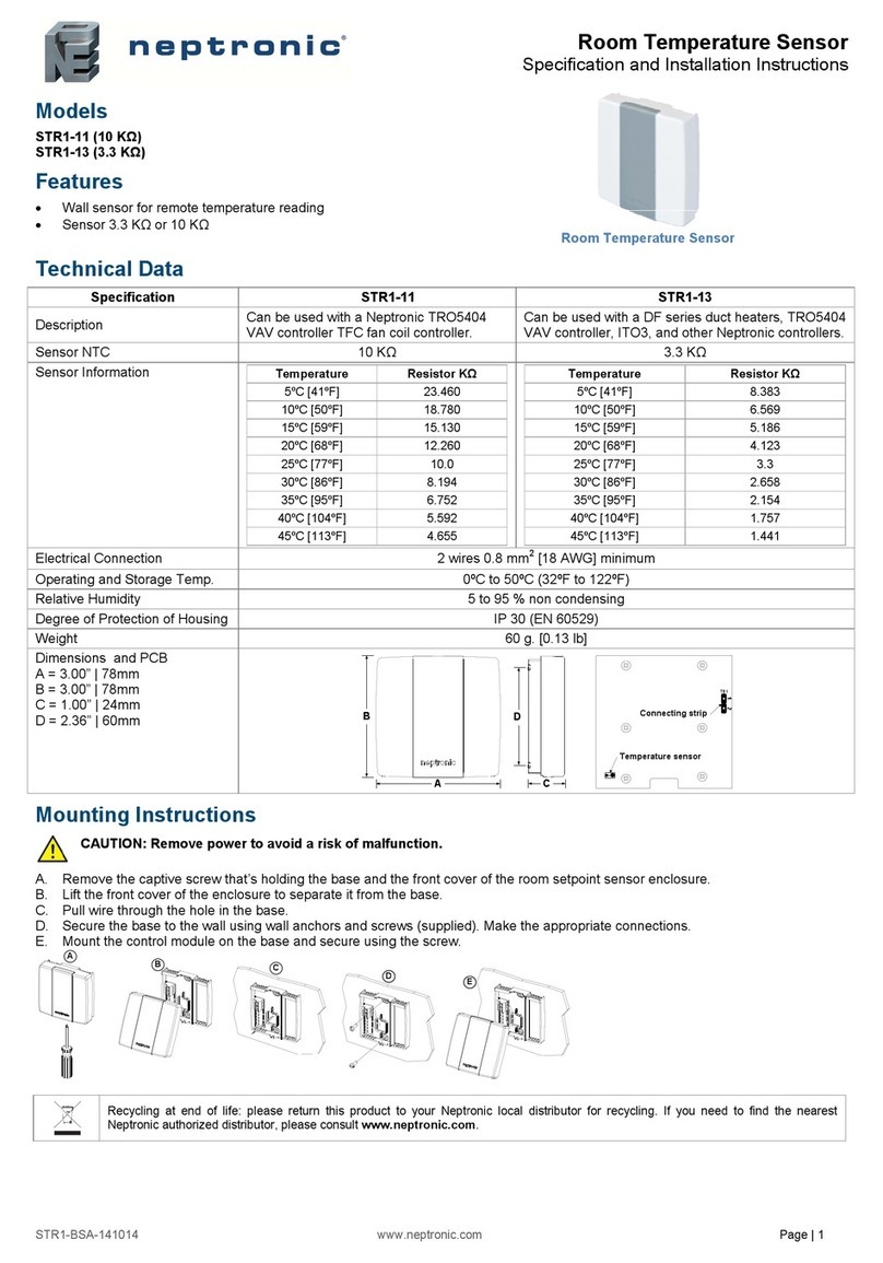
Ïî õàðàêòåðèñòèêàì ÌÂÊ ñîîòâåòñòâóåò òðåáîâàíèÿì ÒÐ ÒÑ 004/2011,
ÒÐ ÅÀÝÑ 037/2016 è ÃÎÑÒ IEC 60947-5-1.
Îñíîâíûå ñâåäåíèÿ îá èçäåëèè
Àâàðèéíûé êîíòàêò ñëóæèò äëÿ ñèãíàëèçàöèè ïîëîæåíèÿ ìåõàíèçìà
âçâîäà âûêëþ÷àòåëåé. Ïåðåêëþ÷åíèå êîíòàêòîâ ïðîèñõîäèò òîëüêî ïðè
ñðàáàòûâàíèè âûêëþ÷àòåëÿ îò ïåðåãðóçîê èëè êîðîòêîãî çàìûêàíèÿ.
Äëÿ èìèòàöèè àâàðèéíîãî ñðàáàòûâàíèÿ íåîáõîäèìî ïîâåðíóòü ðóêîÿòêó òåñò
ïî ÷àñîâîé ñòðåëêå.
Ìîäóëü âñïîìîãàòåëüíûõ êîíòàêòîâ ñåðèè ARMAT òîâàðíîãî çíàêà IEK
(äàëåå – ÌÂÊ) ïðåäíàçíà÷åí äëÿ êîììóòàöèè öåïåé óïðàâëåíèÿ
è ñèãíàëèçàöèè ïåðåìåííîãî èëè ïîñòîÿííîãî òîêà ïðè èçìåíåíèè
êîììóòàöèîííîãî ñîñòîÿíèÿ ãëàâíûõ êîíòàêòîâ. ÌÂÊ ïðåäñòàâëÿåò ñîáîé
ìîäóëü, êîòîðûé êðåïèòñÿ íà çàùåëêó ñ ëåâîé ñòîðîíû ìîäóëüíîãî
îáîðóäîâàíèÿ ñåðèè ARMAT.
Çàïèñü ÌÂÊ ïðè çàêàçå è â äîêóìåíòàöèè äðóãîãî èçäåëèÿ:
Ïåðåêëþ÷àåìûé êîíòàêò ïðåäñòàâëÿåò ñîáîé èçäåëèå òèïà «äâà â îäíîì»:
ìåõàíè÷åñêèé ïåðåêëþ÷àòåëü ïîçâîëÿåò âûáèðàòü ìåæäó äâóìÿ ïàðàìè
êîíòàêòîâ, AS (alarm contact + state contact) – àâàðèéíûé êîíòàêò + êîíòàêò
ñîñòîÿíèÿ èëè 2S (two state contacts) – äâà êîíòàêòà ñîñòîÿíèÿ. Äëÿ èìèòàöèè
àâàðèéíîãî ñðàáàòûâàíèÿ íåîáõîäèìî ïîâåðíóòü ðóêîÿòêó òåñò â ñòîðîíó
îðãàíà óïðàâëåíèÿ.
Êîíòàêò ñîñòîÿíèÿ ñëóæèò äëÿ ïîëó÷åíèÿ èíôîðìàöèè î ñîñòîÿíèè
àâòîìàòè÷åñêèõ âûêëþ÷àòåëåé.
ÌÎÄÓËÜ ÂÑÏÎÌÎÃÀÒÅËÜÍÛÕ ÊÎÍÒÀÊÒÎÂ
ÑÅÐÈÈ ÀRMAT
Êðàòêîå ðóêîâîäñòâî ïî ýêñïëóàòàöèè
234
5 6 7 8
Òåõíè÷åñêèå õàðàêòåðèñòèêè è óñëîâèÿ ýêñïëóàòàöèè
Óòèëèçàöèÿ èçäåëèé ïðîèçâîäèòñÿ ïóò¸ì ïåðåäà÷è ÌÂÊ ñïåöèàëèçè-
ðîâàííûì îðãàíèçàöèÿì.
Ñðîê ñëóæáû ÌÂÊ – 15 ëåò.
Òåõíè÷åñêîå îáñëóæèâàíèå
Ïðè íîðìàëüíûõ óñëîâèÿõ ýêñïëóàòàöèè íåîáõîäèìî ïðîèçâîäèòü
îñìîòð ÌÂÊ îäèí ðàç â ãîä. Íåçàâèñèìî îò ýòîãî îñìîòð ðàñöåïèòåëÿ íóæíî
ïðîèçâîäèòü ïîñëå êàæäîãî îòêëþ÷åíèÿ òîêà êîðîòêîãî çàìûêàíèÿ
àâòîìàòè÷åñêèì âûêëþ÷àòåëåì.
Ïðè îñìîòðå ïðîèçâîäèòñÿ:
– óäàëåíèå ïûëè è ãðÿçè;
– ïðîâåðêà íàäåæíîñòè êðåïëåíèÿ ê âûêëþ÷àòåëþ;
– çàòÿæêà âèíòîâ çàæèìîâ êîíòàêòîâ;
– ïðîâåðêà ðàáîòîñïîñîáíîñòè â ñîñòàâå àïïàðàòóðû ïðè ïðîâåðêå åå
íà ôóíêöèîíèðîâàíèå â ðàáî÷èõ ðåæèìàõ.
Òðàíñïîðòèðîâàíèå ÌÂÊ â ÷àñòè âîçäåéñòâèÿ ìåõàíè÷åñêèõ ôàêòîðîâ
îñóùåñòâëÿåòñÿ ïî ãðóïïå Ñ è Æ ÃÎÑÒ 23216, êëèìàòè÷åñêèõ ôàêòîðîâ –
ïî ãðóïïå 4(Æ2) ÃÎÑÒ 15150.
Òðàíñïîðòèðîâàíèå ÌÂÊ äîïóñêàåòñÿ ëþáûì âèäîì êðûòîãî òðàíñïîðòà
â óïàêîâêå èçãîòîâèòåëÿ, îáåñïå÷èâàþùèì ïðåäîõðàíåíèå óïàêîâàííûõ ÌÂÊ
îò ìåõàíè÷åñêèõ ïîâðåæäåíèé, çàãðÿçíåíèÿ è ïîïàäàíèÿ âëàãè ïðè
òåìïåðàòóðå îò ìèíóñ 40 °Ñ äî ïëþñ 55 °Ñ.
Òðàíñïîðòèðîâàíèå, õðàíåíèå è óòèëèçàöèÿ
Õðàíåíèå ÌÂÊ îñóùåñòâëÿåòñÿ ïî ãðóïïå 1(Ë) ÃÎÑÒ 15150. Õðàíåíèå
ÌÂÊ îñóùåñòâëÿåòñÿ òîëüêî â óïàêîâêå èçãîòîâèòåëÿ â ïîìåùåíèÿõ
ñ åñòåñòâåííîé âåíòèëÿöèåé ïðè òåìïåðàòóðå îêðóæàþùåãî âîçäóõà
îò ìèíóñ 25 °Ñ äî ïëþñ 55 °Ñ è îòíîñèòåëüíîé âëàæíîñòè íå áîëåå 90 % ïðè
òåìïåðàòóðå 20 °Ñ. Äîïóñêàåòñÿ õðàíåíèå ïðè îòíîñèòåëüíîé âëàæíîñòè 50 %
è òåìïåðàòóðå 40 °Ñ.
Ñðîê ñëóæáû è ãàðàíòèè èçãîòîâèòåëÿ
Ïðè âîçíèêíîâåíèè ïðåòåíçèé â ïåðèîä ãàðàíòèéíûõ îáÿçàòåëüñòâ
îáðàùàòüñÿ ê ïðîäàâöó èëè â îðãàíèçàöèè:
Ãàðàíòèéíûé ñðîê ýêñïëóàòàöèè ÌÂÊ – 10 ëåò ñ äàòû ïðîäàæè
ïîòðåáèòåëþ ïðè óñëîâèè ñîáëþäåíèÿ ïîòðåáèòåëåì òðåáîâàíèé
òðàíñïîðòèðîâàíèÿ, õðàíåíèÿ è ýêñïëóàòàöèè.
Ñõåìû ýëåêòðè÷åñêèå ïðèíöèïèàëüíûå ÌÂÊ
Ãàáàðèòíûå è óñòàíîâî÷íûå ðàçìåðû ÌÂÊ
Ïåðåä ìîíòàæîì íåîáõîäèìî îçíàêîìèòüñÿ ñ ðóêîâîäñòâîì ïî
ýêñïëóàòàöèè èçäåëèÿ, ñ êîòîðûì áóäåò ñîñòûêîâàí ÌÂÊ.
Èñïîëüçîâàòü ÌÂÊ ïðè îáðàçîâàíèè òðåùèí èëè ñêîëîâ íà êîðïóñå
â ïðîöåññå ýêñïëóàòàöèè.
Ìîíòàæ
Ìåðû áåçîïàñíîñòè
Âñå ìîíòàæíûå è ïðîôèëàêòè÷åñêèå ðàáîòû ñëåäóåò ïðîâîäèòü ïðè
ñíÿòîì íàïðÿæåíèè.
Ïî ñïîñîáó çàùèòû îò ïîðàæåíèÿ ýëåêòðè÷åñêèì òîêîì âûêëþ÷àòåëè
ñîîòâåòñòâóþò êëàññó 0 ïî ÃÎÑÒ Ð 12.1.019 è äîëæíû óñòàíàâëèâàòüñÿ
â ðàñïðåäåëèòåëüíîå îáîðóäîâàíèå, èìåþùåå êëàññ çàùèòû íå íèæå I.
Ýêñïëóàòàöèÿ ÌÂÊ äîëæíà ïðîèçâîäèòüñÿ â ñîîòâåòñòâèè ñ «Ïðàâèëàìè
óñòðîéñòâ ýëåêòðîóñòàíîâîê», «Ïðàâèëàìè òåõíè÷åñêîé ýêñïëóàòàöèè
ýëåêòðîóñòàíîâîê ïîòðåáèòåëåé» è «Ìåæîòðàñëåâûìè ïðàâèëàìè ïî îõðàíå
òðóäà (ïðàâèëàìè áåçîïàñíîñòè) ïðè ýêñïëóàòàöèè ýëåêòðîóñòàíîâîê».
ÇÀÏÐÅÙÀÅÒÑß
– ÌÂÊ – 1 øò.;
Êîìïëåêòíîñòü
– ïàñïîðò – 1 ýêç.
 êîìïëåêò ïîñòàâêè âõîäèò:
Èçäàíèå 3
Çàïèñü ÌÂÊ ïðè çàêàçå è â äîêóìåíòàöèè äðóãîãî èçäåëèÿ
Àðòèêóë
ARMAT Êîíòàêò ñîñòîÿíèÿ AR-AUX 240...415 Â IEK
AR-AUX-SC-240-415
ARMAT Àâàðèéíûé êîíòàêò AR-AUX 240...415 Â IEK
AR-AUX-AC-240-415
ARMAT Ïåðåêëþ÷àåìûé êîíòàêò AR-AUX 240...415  IEK
AR-AUX-DC-240-415
Ïàðàìåòðû
Çíà÷åíèå
– ïîñòîÿííîãî òîêà
Íîìèíàëüíîå ðàáî÷åå íàïðÿæåíèå, Ue, Â
– ïåðåìåííîãî òîêà ÷àñòîòîé 50/60 Ãö
24…130
240…415
Êàòåãîðèÿ ïðèìåíåíèÿ
DC-12, ÀÑ-12
Íîìèíàëüíîå íàïðÿæåíèå èçîëÿöèè, Â
415
Óñëîâíûé òåïëîâîé òîê Ith, À
6
Íîìèíàëüíîå èìïóëüñíîå âûäåðæèâàåìîå íàïðÿæåíèå, êÂ
4
Ñòåïåíü çàùèòû ïî ÃÎÑÒ 14254 (IEC 60529)
IP20
Ìåõàíè÷åñêàÿ èçíîñîñòîéêîñòü, öèêëîâ Â-Î
20000
2
Ñå÷åíèå ïðèñîåäèíÿåìûõ ïðîâîäîâ, ìì
1–2,5
Òèïû ñîâìåñòèìûõ àâòîìàòè÷åñêèõ âûêëþ÷àòåëåé
ARMAT
Ïðèñîåäèíåíèå ê àâòîìàòè÷åñêîìó âûêëþ÷àòåëþ
ñëåâà
Ðåìîíòîïðèãîäíîñòü
íåðåìîíòîïðèãîäåí
Ðåæèì ðàáîòû
ïðîäîëæèòåëüíûé
Ìîìåíò çàòÿæêè âèíòîâ êîíòàêòíûõ çàæèìîâ ïðè èñïîëüçîâàíèè îòâåðòêè,
ÍЧì, íå áîëåå
0,8
Ìàññà, êã, íå áîëåå
0,045
Äèàïàçîí ðàáî÷èõ òåìïåðàòóð, °Ñ
îò ìèíóñ 40 äî ïëþñ 70
– ïðè 40 °Ñ
– ïðè 20 °Ñ
Îòíîñèòåëüíàÿ âëàæíîñòü âîçäóõà, %:
50
90
Âûñîòà íàä óðîâíåì ìîðÿ, ì
Ј 2000
Ðàáî÷åå ïîëîæåíèå
ëþáîå
Ðåæèìû êîììóòàöèè ÌÂÊ
Ðîä òîêà
Êàòåãîðèÿ ïðèìåíåíèÿ
Íàïðÿæåíèå, Â
Òîê, À
Ïåðåìåííûé
ÀÑ-12
240
6
415
3
ïîñòîÿííûé
DC-12
48
2
130
1
11 91
11
12 92
12
14 94
14
24 22 21 919492
14 12 11
или
Êîíòàêò ñîñòîÿíèÿ Àâàðèéíûé êîíòàêò
Àâàðèéíûé êîíòàêò
Ïåðåêëþ÷àþùèé êîíòàêò
ïîëîæåíèå ASïîëîæåíèå 2S
Ïåðåêëþ÷àþùèé êîíòàêò
9 max
13,3 max
81,5 max
35,5 max
23
43,7
45 max
63,7
70,3 max
5,5
Тест
Индикатор аварийного
срабатывания
81,5 max
9 max
13,3 max
45 max
70,3 max
63,7
43,7 5,5
35,5 max
23
Êîíòàêò ñîñòîÿíèÿ
9 max
13,3 max
81,5 max
A
Индикатор положения механического
5,5 43,7
63,7
23
45 max
35,5 max
70,3 max
Индикатор аварийного
Тест
срабатывания
A
Механический
переключатель
переключателя
SD
OF
– âåðõíèé çàöåï ÌÂÊ âñòàâèòü â âåðõíèé ïàç îñíîâíîãî óñòðîéñòâà;
– ïîâåðíóòü ÌÂÊ ïðîòèâ ÷àñîâîé ñòðåëêè äî ñîâìåùåíèÿ øòèôòà
è âûñòóïîâ â ðó÷êå è áîêîâèíå ñ îòâåðñòèÿìè îñíîâíîãî óñòðîéñòâà. Ïëîòíî
ïðèæìèòå ÌÂÊ ê îñíîâíîìó óñòðîéñòâó è çàùåëêà ÌÂÊ, ñîâìåñòèâøèñü
ñ âåðõíèì ïàçîì îñíîâíîãî óñòðîéñòâà, çàôèêñèðóåòñÿ â íåì;
– ïîñëå ïðèñîåäèíåíèÿ âêëþ÷èòü îñíîâíîå óñòðîéñòâî. Ðó÷êà äîëæíà
÷åòêî ôèêñèðîâàòüñÿ âî âêëþ÷åííîì ïîëîæåíèè «I», à èíäèêàòîð
âûêëþ÷àòåëÿ, ÀÂÄÒ, ÂÄÒ äîëæåí áûòü êðàñíîãî öâåòà.
– ðó÷êè âñåõ óñòðîéñòâ ïåðåâåñòè â îòêëþ÷åííîå ïîëîæåíèå;
Ïðèñîåäèíåíèå ÌÂÊ ê âûêëþ÷àòåëþ, ÀÂÄÒ, ÂÄÒ, ÐÍ (äàëåå – îñíîâíîìó
óñòðîéñòâó) ïðîâîäèòü â ñëåäóþùåé ïîñëåäîâàòåëüíîñòè:
Äîïóñêàåòñÿ ñîñòûêîâêà íå áîëåå äâóõ óñòðîéñòâ.
1

ARMAT
Basic information about product
The module of auxiliary contacts of the ARMAT series of the IEK trademark
(hereinafter referred to as – MVK) is designed for switching of the control circuits
and signaling of AC and DC when the switching state of the main contacts changes.
MVK is a module that is latched on the left side of the modular ARMAT series
equipment.
The state contact serves to obtain information about the state of the circuit
breakers.
The MVK correspond to the requirements LVD Directive No. 2014/35/EU and
RoHS 2011/65/EU.
The switched contact is a two-in-one product: a mechanical switch allows
selecting between two pairs of contacts, AS (alarm contact + state contact) – alarm
contact + state contact or 2S (two state contacts) – two state contacts. To simulate
emergency operation, turn the test handle towards the control.
The emergency contact serves to signal the position of the circuit breaker
cocking mechanism. Switching of contacts occurs only when the breaker operates
from overloads or short circuits. To simulate an emergency operation, turn the test
handle towards the control unit.
Record of MVK when ordering and in the documentation of another product:
MODULE OF AUXILIARY CONTACTS
OF ÀRMAT SERIES
Operation manual
234
5 6 7 8
Specifications and operating conditions
– checking the reliability of fastening to the switch;
If you have any claims during the warranty period, contact the seller or
organization:
– removal of dust and dirt;
Transportation of MVK is allowed by any type of covered transport in the
manufacturer's packaging, ensuring the protection of the packed MVK from
mechanical damage, pollution and moisture at temperatures from minus 40 °Ñ
to plus 55 °Ñ.
Maintenance
When inspection, the following actions are carried out:
– performance check as part of the equipment when checking it for
functioning in operating modes.
Warranty period of MVK – 10 years from the date of sale to the consumer,
under observance of that the consumer meets the requirements of transportation,
storage and operation.
– tightening the screws of the terminals;
Disposal of products is carried out by transferring MVK to specialized
organizations.
Service life of MVK – 15 years.
Under normal operating conditions, it is necessary to inspect the MVK once
a year. Regardless of this, an inspection of the release should be carried out after
each interruption of the short-circuit current by the circuit breaker.
Service life and manufacturer's warranty
Transportation, storage and disposal
Storage of MVK is carried out only in the manufacturer's packaging in rooms
with natural ventilation at an ambient temperature of minus 25 °Ñ to plus 55 °Ñ and
relative humidity of no more than 90 % at a temperature of 20 °Ñ. Storage is
allowed at 50 % relative humidity and 40 °C.
Electric schematic diagrams of MVK
Overall and mounting dimensions of MVK
All installation and maintenance work should be carried out in de-energized
state.
The operation of the MVK should be carried out in accordance with the «Rules
on design of power electric installations», «Rules of technical operation of electric
installations of consumers» and «Interindustry labor safety rules (safety rules) for
the operation of electric installations».
Installation
Safety precautions
To use MVK when formation of cracks or chips on the case during operation.
IT IS FORBIDDEN
Before installation, you must familiarize yourself with the operation manual of
the product with which the MVK will be docked.
– MVK – 1 pcs.;
Completeness of set
– ðassport – 1 copy.
Òhe delivery package includes:
Version 3
Record of MVK when ordering and in the documentation of another product
Item
ARMAT state contact AR-AUX 240...415 V IEK
AR-AUX-SC-240-415
ARMAT emergency contact AR-AUX 240...415 V IEK
AR-AUX-AC-240-415
ARMAT switched contact AR-AUX 240...415 V IEK
AR-AUX-DC-240-415
Switching mode of MVK
Kind of current
Utilization ategory
Voltage, V
Current, À
AC
ÀÑ-12
240
6
415
3
DC
DC-12
48
2
130
1
11 91
11
12 92
12
14 94
14
24 22 21 919492
14 12 11
or
State contact Emergency contact
Emergency contact
Switched contact
Switched contact
9 max
13,3 max
81,5 max
35,5 max
23
43,7
45 max
63,7
70,3 max
5,5
Test
Emergency activation
indicator
81,5 max
9 max
13,3 max
45 max
70,3 max
63,7
43,7 5,5
35,5 max
23
State contact
9 max
13,3 max
81,5 max
A
Position indicator of mechanical
5,5 43,7
63,7
23
45 max
35,5 max
70,3 max
Emergency activation
Test
indicator
A
Mechanical
switch
switch
SD
OF
Connect MVK to the circuit breaker, RCBO, RCCB, Shunt Release (hereinafter
referred to as – the main device) in the following sequence:
– insert the upper hook of the MVK into the upper groove of the main device;
– turn the MVK counterclockwise until the pin and protrusions in the handle
and sidewall are aligned with the holes of the main device. Press the MVK firmly to
the main device and the MVK latch, aligning with the upper groove of the main
device, will fix in it;
– after connecting, turn on the main device. The handle should be clearly fixed
in the on position "I", and the indicator of the circuit breaker, RCBO, RCCB should
be red.
Docking of no more than two devices is allowed.
– move the handles of all devices to the off position;
Parameters
Value
– of DC
– of AC with frequency of 50/60 Hz
Rated voltage, Ue, V
240…415
24…130
Utilization category
DC-12, ÀÑ-12
Rated insulation voltage, V
415
Conventional thermal current Ith, À
Rated impulse withstand voltage, kV
4
Degree of protection according to IEC 60529
IP20
Mechanical wear resistance, ON-OFF cycles
20000
2
Cross section of connected conductors, mm
1–2,5
Types of compatible circuit breakers
ARMAT
Ñonnection to the circuit breaker
left-handed
Repairability
none repairable
Operation mode
maintained
Tightening torque for terminal screws when using a screwdriver, NЧm, maximum
0,8
Weight, kg, maximum
0,045
Operating temperature range, °Ñ
From minus 40 up to plus 70
– at 40 °Ñ
Relative air humidity, %:
– at 20 °Ñ
50
90
Base altitude, m
Ј 2000
Operation position
any
1
AS position2S position
This manual suits for next models
3
