IEP 30917 User manual
Operating Instructions
Balancer for Multifunction Plug (30917)

Imprint:
All Rights Reserved. Duplication of these instructions or parts thereof by any reproduction
method whatsoever is prohibited without the prior permission of Industrieelektronik Pölz
GmbH.
These operating instructions do not represent a contractual relationship.
We reserve the right to make changes errors and omissions excepted.
© Copyright 2017 Industrieelektronik Pölz GmbH

OPERATING INSTRUCTIONS
Balancer
3
TABLE OF CONTENTS
1Introduction ................................................................................................. 4
1.1 Liability and Warranty ..............................................................................................4
1.2 Customer Service.....................................................................................................4
1.3 About these Operating Instructions..........................................................................4
1.4 Explanation of Symbols and Instructions...................................................................5
2Safety Information ........................................................................................ 5
2.1 Intended Use ...........................................................................................................5
3Description of the Device .............................................................................. 6
3.1 Device Types............................................................................................................6
3.2 Type Plate................................................................................................................6
3.3 Device Overview ......................................................................................................6
4Installation ................................................................................................... 7
4.1 Unpacking the Balancer ...........................................................................................7
4.2 Installing the Balancer..............................................................................................7
4.2.1 Installing the Balancer in a Fixed Position..................................................................7
4.2.2 Installing the Balancer in a Movable Position ............................................................8
4.3 Suspending a Load ..................................................................................................8
4.4 Setting the Balancer.................................................................................................8
4.4.1 Increasing the Load-bearing Capacity.......................................................................9
4.4.2 Reducing the Load-bearing Capacity ........................................................................9
4.4.3 Setting the Rope Length ..........................................................................................9
5Operation................................................................................................... 10
6Dismantling ................................................................................................ 10
6.1 Setting Down the Load ..........................................................................................10
7Service ....................................................................................................... 10
7.1 Maintenance .........................................................................................................10
7.2 Cleaning................................................................................................................10
7.3 Repairs ..................................................................................................................10
8Appendix.................................................................................................... 11
8.1 Technical Data.......................................................................................................11
8.2 Disposal.................................................................................................................11
8.3 Declaration of Conformity (DoC)............................................................................11

1
OPERATING INSTRUCTIONS
Balancer
4
1Introduction
•The balancer pulls the multifunction
plug including the cable above head
height and keeps your workplace
clean and tidy.
•Over the entire rope range, the bal-
ancer has a uniform load-bearing ca-
pacity that you can set between 2 and
3 kg with a rope length of 1.6 m.
•You can set the retractable rope
length so that it is possible to keep the
multifunction plug within reach in dif-
ferent installation situations.
•The balancer consists of a sturdy die-
cast aluminium housing, flexible and
resilient stainless steel wire rope and is
characterized by its precise rope guid-
ance and the spring that is designed
for a long service life.
•Can be mounted on ceilings and walls.
1.1 Liability and Warranty
Use the balancer only in accordance with
its intended use (see also Chapter 2.1
INTENDED USE).
The manufacturer warranties the balancer
within the scope of the conditions of sale
and delivery that apply in each case.
The manufacturer accepts no liability for
damage due to ignoring the information
in these operating instructions as well as
to incorrectly assembling, operating or
servicing the balancer.
1.2 Customer Service
If you need technical information or have
any queries or need to order spare parts,
please contact your local dealer or e-mail
our customer service: office@poelz.at
To ensure that your inquiry is processed
quickly, please state the following infor-
mation:
•Device type
•Item number
You can find the device type on the type
plate (see also Chapter 3.2 TYPE PLATE). For
information on the item number, see also
Chapter 8.1 TECHNICAL DATA.
1.3 About these Operating Instruc-
tions
These operating instructions are a compo-
nent of the scope of supply; you must
always keep them at the location of the
balancer.
The guide includes all the information you
need for assembling the balancer, for
operating, servicing, dismantling and
disposing of it.
Read the operating instructions carefully
before using the system and observe the
safety and warning instructions to ensure
perfect operation of your balancer.

2
OPERATING INSTRUCTIONS
Balancer
5
1.4 Explanation of Symbols and
Instructions
This symbol warns you of a
hazard. This signal word de-
scribes the severity of the im-
minent danger.
Danger!
Personal injury can occur in the
case of incorrect handling.
Caution!
Damage to equipment or
property can occur in the case
of incorrect handling.
Danger electrical hazard!
This symbol warns you of an
electrical hazard.
Touching live parts can lead to
injury or even be fatal.
Fire hazard!
This symbol warns you of a fire
hazard.
Note!
This symbol indi-
cates tips and
useful infor-
mation on han-
dling the balancer
in the best possi-
ble way.
2Safety Information
The balancer has been manufactured and
inspected in accordance with valid stand-
ards and guidelines and recognized tech-
nical regulations. However, incorrect use
can lead to physical harm to users or
damage to the balancer or other material
assets.
Always comply to the letter with the safe-
ty information and warnings given in
these operating instructions.
2.1 Intended Use
The balancer is intended exclusively for
pulling a multifunction plug including the
cable up above head height as well as for
use indoors; it has a load-bearing capacity
of 2 to 3 kg.
3
OPERATING INSTRUCTIONS
Balancer
6
3Description of the
Device
3.1 Device Types
In these operating instructions, we will
describe the following device types.
•Balancer for multifunction plug
Item number: 30917
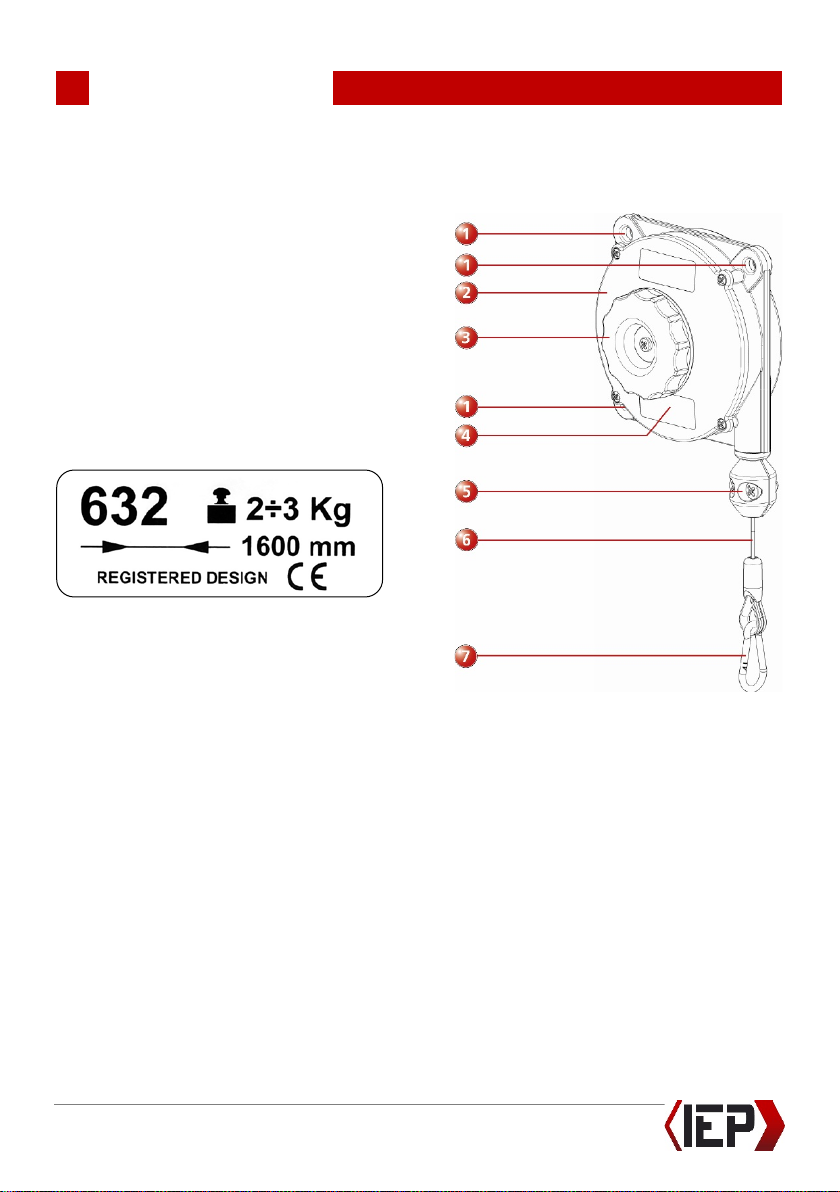
3.2 Type Plate
3.3 Device Overview
① Fastening holes
②Housing
③Rotary knob for setting the
load-bearing capacity
④Type plate
⑤Rope clamp
⑥Rope
⑦Snap hook
4
OPERATING INSTRUCTIONS
Balancer
7
4Installation
Danger!
Mount the balancer such that
it does not endanger anybody.
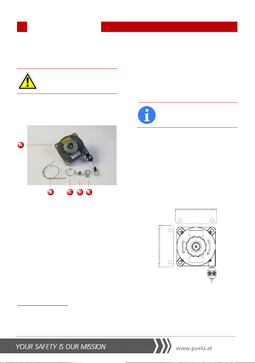
4.1 Unpacking the Balancer
Remove the packaging material.
ABalancer
BRetaining rope
CRing
DClamp
ESnap hook
Operating Instructions
Check that the contents of the package
are complete and inspect for possible
damage. If any components are missing or
are
damaged, contact our customer service
immediately (see also Chapter
1.2 CUSTOMER SERVICE).
4.2 Installing the Balancer
You can install the balancer on the wall or
on the ceiling by attaching it to a suitable
bracket. The bracket must be attached
securely to the ceiling of the hall and have
adequate load-bearing capacity.
Note!
Install the balancer such that
the rope can be moved freely.
Choose an installation height at which the
central part of the rope is loaded and
where you can easily reach the balancer
when the rope is retracted.
4.2.1 Installing the Balancer in a
Fixed Position
Screw the balancer in a fixed horizontal or
vertical position in at least two fastening
holes (①).
Use M8 nuts and bolts with a locking
device to prevent loosening (e.g. self-
locking hexagon nuts as per EN
10511/DIN 985).

4
OPERATING INSTRUCTIONS
Balancer
8
4.2.2 Installing the Balancer in a
Movable Position
Note!
We recommend installing the
balancer in a movable position
to ensure that the rope is not
subjected to friction.
Use the supplied snap hook (B) to fasten
the balancer and secure it with the retain-
ing rope (C) on the bracket, which you
should attach separately if possible.
Make sure that adequate lengths of the
retaining rope (C) are routed above one
another and that the clamp (D) blocks
both sections of the ropes that are on top
of one another.
4.3 Suspending a Load
Danger!
When suspending a load, hold
the rope tight, e.g. on the rope
cla
mp (⑤); otherwise, it could
fly back and cause injuries.
Use suitable, safe fastenings to suspend
the multifunction plug including the cable.
Note!
If you choose to install the
balancer in a fixed position,
you can use the supplied
securing components
like the
rope, clamp and ring, for
example, to suspend the mul-
tifunction plug.
4.4 Setting the Balancer
Caution!
Make sure that the rope is not
pulled out completely. There
should be at least 5
cm left.
If necessary, move the rope
clamp (
⑤) and lock it to limit
the lift upwards.
Estimate the weight of the multifunction
plug including the cable. You can find
details of the weight of the multifunction
plug in the combined plug and socket
operating instructions.
Set the necessary load-bearing capacity on
the rotary knob (③). The setting range
for the load-bearing capacity is between 2
and 3 kg.

4
OPERATING INSTRUCTIONS
Balancer
9
The arrows on the housing (②) show the
direction of rotation to increase or reduce
the load-bearing capacity.
4.4.1 Increasing the Load-bearing
Capacity
Turn the rotary knob (③)to the left (anti-
clockwise) to increase the load-bearing
capacity.
4.4.2 Reducing the Load-bearing
Capacity
Turn the rotary knob (③)to the right
(clockwise) to reduce the load-bearing
capacity.
4.4.3 Setting the Rope Length
If you want to set a rope length of less
than 1.6 m, proceed as follows:
1. Loosen the screws on the rope clamp
(⑤) until you can move it.
2. Position the rope clamp (⑤)at the
desired position.
3. Tighten up the screws.
5
OPERATING INSTRUCTIONS
Balancer
10
5Operation
Check the condition of the rope (⑥) at
regular intervals.
On a regular basis, check that the parts
under load are secure and have not been
weakened by wear.
Make sure that the load-bearing capacity
is always set correctly.
6Dismantling
6.1 Setting Down the Load
Danger!
When setting down a load,
hold the rope tight, e.g. on the
rope clamp (
⑤); otherwise, it
could fly back and cause inju-
ries.
7Service
Danger!
Servicing work must only be
carried out by qualified people
who have been tasked with this
work.
7.1 Maintenance
Note!
The balancer is
maintenance-
free.
If particularly heavy loading makes it nec-
essary to carry out repairs, contact cus-
tomer service (see Chapter 1.2 CUSTOMER
SERVICE).
7.2 Cleaning
Always keep the rope and the area round
the rope draw-in device clean.
7.3 Repairs
Danger!
Only the manufacturer or a
qualified service engineer are
allowed to replace springs.
Under no circumstances try to carry out
repairs yourself.

8
OPERATING INSTRUCTIONS
Balancer
11
8Appendix
8.1 Technical Data
Load-bearing capacity (can be set steplessly
using the rotary button)
2 – 3 kg
Rope Stainless steel, ø 2 mm
Rope length (can be set shorter) 1.6 m
Fastening holes Ø 8 mm
Weight 0.790 kg approx.
Housing Die-cast aluminium
Item number 30917
8.2 Disposal
Balancer
At the end of its useful life, never throw
away the balancer in domestic refuse
under any circumstances. Consult your
local council about the options available
for correct environmentally friendly dis-
posal.
Packaging
Observe locally applicable regulations for
correct recycling.
8.3 Declaration of Conformity
(DoC)
The CE mark confirms conformity of the
device with the relevant EU directives.
To obtain the complete declaration of
conformity, please contact our customer
service: offic[email protected]

31064_Bedienungsanleitung Balancer_Englisch_03/03/2017
Central Office
Office
Germany
Industrieelektronik Pölz GmbH IEP Pölz GmbH
Großendorf 122 Laufener Straße 15a
4551 Ried im Traunkreis, Austria 83395 Freilassing, Germany
Tel.: +43 (0)7588 - 70 122 Tel.: +49 (0)8654 - 478 670
Fax: +43 (0)7588 - 70 125 Fax: +49 (0)8654 - 478 673
E-Mail: office@poelz.at E-Mail: office@poelz.at
Web: www.poelz.at Web: www.poelz.at
Table of contents
Other IEP Tools manuals


