IEP Spidy ROLLER 230 V User manual

Operating Instructions
Spidy ROLLER 230 V (30222)
Spidy AIRROLLER 230 V (30226)
Spidy AIRROLLER 230 V with Multifunctional Plug (30876)
Spidy ROLLER 12/24 V (30569)
Spidy ROLLER 12/24 V with 7-Pole Plug (30679)
Spidy AIRROLLER 12/24 V (30223)
Spidy AIRROLLER 12 / 24 V with Combined Air Plug (30677)
Spidy AIRROLLER 12/24 V with Multifunctional Plug (30875)

Imprint:
All Rights Reserved. Duplication of these instructions or parts thereof by any reproduction
method whatsoever is prohibited without the prior permission of Industrieelektronik Pölz
GmbH.
These operating instructions do not represent a contractual relationship.
We reserve the right to make changes errors and omissions excepted.
© Copyright 2017 Industrieelektronik Pölz GmbH

OPERATING INSTRUCTIONS
Spidy Cable Reel
3
TABLE OF CONTENTS
1
Introduction .................................................................................................. 5
1.1 Liability and Warranty ...............................................................................................5
1.2 Customer Service......................................................................................................5
1.3 About these Operating Instructions...........................................................................6
1.4 Explanation of Symbols and Instructions....................................................................6
2
Safety Information ......................................................................................... 7
2.1 Intended Use ............................................................................................................7
2.2 General Safety Information ......................................................................................7
3
Description of the Device ............................................................................... 8
3.1 Device Overview .......................................................................................................8
3.2 Device Types.............................................................................................................8
3.3 Description of Function.............................................................................................9
3.4 Technical Description ................................................................................................9
3.4.1 Cable Stopper.........................................................................................................10
3.4.2 Cable Locking.........................................................................................................10
3.4.3 Fuse .......................................................................................................................10
4
Installation .................................................................................................. 12
4.1 Unpacking the Cable Reel.......................................................................................12
4.2 Mounting the Cable Reel ........................................................................................13
4.3 Connecting the Cable Reel......................................................................................14
4.3.1 Connecting a Spidy ROLLER 12 V / 24 V (without Compressed Air Supply) to the
Battery Testing and Charging System ......................................................................14
4.3.2 Connecting a Spidy ROLLER 12 V / 24 V (with Compressed Air Supply) to the
Battery Testing and Charging System ......................................................................15
4.3.3 Connecting a Spidy ROLLER 230 V (without Compressed Air Supply) to the
Mains Supply..........................................................................................................15
4.3.4 Connecting a Spidy ROLLER 230 V (with Compressed Air Supply) to the
Mains Supply..........................................................................................................16
5
Operation.................................................................................................... 18
6
Dismantling................................................................................................. 19
6.1.1 Dismounting the Cable Reel....................................................................................19

OPERATING INSTRUCTIONS
Spidy Cable Reel
4
7
Service ........................................................................................................ 20
7.1 Maintenance ..........................................................................................................20
7.1.1 Checking and Replacing Fuses ................................................................................20
7.1.2 Checking and Replacing Cables ..............................................................................21
7.1.3 Replacing Springs ...................................................................................................22
8
Appendix .................................................................................................... 23
8.1 Technical Data........................................................................................................23
8.1.1 Spidy ROLLER 12 V / 24 V (without Compressed Air Supply) ....................................23
8.1.2 Spidy ROLLER 12 V / 24 V (with Compressed Air Supply) .........................................23
8.1.3 Spidy ROLLER 230 V (without Compressed Air Supply) ............................................24
8.1.4 Spidy AIRROLLER 230 V (with Compressed Air Supply) ............................................24
8.2 Disposal..................................................................................................................25
8.3 Test Certificates......................................................................................................25
8.4 Declaration of Conformity (DoC).............................................................................25

1
OPERATING INSTRUCTIONS
Spidy Cable Reel
5
1
Introduction
The Industrieelektronik Pölz GmbH battery
automatic cable reel that you have pur-
chased is a high-quality product. Here is
an overview of the most important bene-
fits that you will enjoy:
•A tried and tested cable reel with
spring return – designed as a work-
shop cable drum – for supplying pow-
er and compressed air in one cable.
•Industrial version designed for rolling
and unrolling at least 30,000 times.
•Can be mounted on ceilings and walls.
•The length of the cable adapts auto-
matically to different workplaces. You
only pull out the length of cable that
you need at any one time. The cable
that you do not need is protected
from contamination and damage.
•The cable reel keeps everything neat
and tidy in your workshop by avoiding
tangled cables that represent a trip-
ping hazard.
•High levels of convenience due to the
cable locking and individual stop de-
vice settings.
•The cable reel is compatible with
Industrieelektronik Pölz GmbH's com-
bined plugs and sockets.
1.1
Liability and Warranty
Use the cable reel only in accordance with
its intended use (see also Chapter
2.1
INTENDED USE
).
The manufacturer warranties the cable
reel within the scope of the conditions of
sale and delivery that apply in each case.
The manufacturer accepts no liability for
damage due to ignoring the information
in these operating instructions as well as
to incorrectly assembling, operating or
servicing the cable reel.
1.2
Customer Service
If you need technical information or have
any queries or need to order spare parts,
please contact your local dealer or e-mail
To ensure that your inquiry is processed
quickly, please state the following infor-
mation:
•Device type
•Item number
For information on the item number, see
also Chapter
3.2 DEVICE TYPES
. For infor-
mation on the item number, see also
Chapter
8.1 TECHNICAL DATA
.

1
OPERATING INSTRUCTIONS
Spidy Cable Reel
6
1.3
About these Operating In-
structions
These operating instructions are a compo-
nent of the scope of supply; you must
always keep them at the location of the
cable reel.
The guide includes all the information you
need for assembling the cable reel, for
operating, servicing, dismantling and
disposing of it.
Read the operating instructions carefully
before using the system and observe the
safety and warning instructions to ensure
perfect operation of your cable reel.
1.4
Explanation of Symbols and
Instructions
This symbol warns you of a
hazardous location. This signal
word describes the severity of
the imminent danger.
Danger!
Personal injury can occur in the
case of incorrect handling.
Caution!
Damage to equipment or
property can occur in the case
of incorrect handling.
Danger, electrical hazard!
This symbol warns you of an
electrical hazard.
Touching live parts can lead to
injury or even be fatal.
Fire hazard!
This symbol warns you of a fire
hazard.
Note!
This symbol indicates tips and
useful information on ha
n-
dling the cable reel in the best
possible way.

2
OPERATING INSTRUCTIONS
Spidy Cable Reel
7
2
Safety Information
Always comply to the letter with the safe-
ty information and warnings given in
these operating instructions.
2.1
Intended Use
The cable reel with spring return is in-
tended exclusively for connecting and / or
extending the supply of power to battery
systems and (depending on the device
type) of compressed air to the braking
systems of vehicles.
The 12/24 V cable reel with or without a
compressed air supply is for supplying the
battery testing and charging system (or a
similar device) that is installed in the vehi-
cle hall.
The 230 V cable reel with or without a
compressed air supply is for supplying the
battery testing and charging system (or a
similar device) that is installed in the vehi-
cle.
The cable reel with spring return is de-
signed to be used manually.
Any other use is not the intended use and
voids the warranty.
2.2
General Safety
Information
This cable reel is not intended for use by
anybody (including children) with physical,
sensory or mental challenges, who are
inexperienced or do not have adequate
knowledge unless they are supervised by a
person who is responsible for their safety
or who gives them instructions on using
the cable reel.
Do not allow any children to handle the
cable reel without supervision.
Installation, dismantling and service work
may only be carried out by qualified per-
sons who have been assigned to carry out
this work.
Hold the cable tight when pulling it out or
reeling it back; otherwise, the spring
return can lead to the cable snapping
back and causing injury.
Do not overtension the cable (e.g. by
hanging weights from it). Do not use
force to pull the cable, since this can
damage the device.
When reeled-up, the cable can become
very hot in the case of severe inductive
loading. If under heavy load, pull the cable
out completely.

3
OPERATING INSTRUCTIONS
Spidy Cable Reel
8
3
Description of the
Device
3.1
Device Overview
Note!
The cable stopper only pr
e-
vents the cable from snapping
back to the set gripping height.
3.2
Device Types
Supplying with power and compressed air
is conditional upon the Industrieelektronik
Pölz GmbH battery testing and charging
system (or a similar device) being installed
in the vehicle hall or the vehicle.
The 12 V / 24 V cable reel with or without
a compressed air supply is for supplying
the battery testing and charging system
(or a similar device) that is installed in the
vehicle hall.
The 230 V cable reel with or without a
compressed air supply is for supplying the
battery testing and charging system (or a
similar device) that is installed in the vehi-
cle.
In these operating instructions, we will
describe the following device types:
Without 12 V / 24 V compressed air
supply
•
Spidy ROLLER 12 V / 24 V
Item number: 30569
for the power supply
•
Spidy ROLLER 12 V / 24 V
with 7-pole plug
Item number: 30679
for the power supply

3
OPERATING INSTRUCTIONS
Spidy Cable Reel
9
With 12 V / 24 V compressed air
supply
•
Spidy AIRROLLER 12 V / 24 V
Item number: 30223
for supplying power and compressed
air
•
Spidy AIRROLLER 12 V / 24 V
with Spidy 12/24 V combined air
plug
Item number: 30677
for supplying power and compressed
air
•
Spidy AIRROLLER 12 V / 24 V with
multifunctional plug for socket
Item number: 30875
for supplying power and compressed
air
Without 230 V compressed air sup-
ply
•
Spidy ROLLER 230 V
Item number: 30222
With 230 V compressed air supply
•
Spidy AIRROLLER 230 V
Item number: 30226
•
Spidy AIRROLLER 230 V with mul-
tifunctional plug for socket
Item number: 30876
Please note the device-specific description
and equipment of your cable reel.
Note!
The cable reel is compatible
with Industrieelektronik Pölz
GmbH's combined plugs and
sockets.
You can order combined plugs
and sockets from our customer
service (see also
ter 1.2 CUSTOMER SERVICE
).
3.3
Description of Function
The cable reel is for connecting and / or
extending the supply of power and (de-
pending on the device type) of com-
pressed air to vehicles or battery systems.
The cable length (a maximum of 6.30 m
and with the Spidy ROLLER 230 V up to a
maximum of 8 m) adapts automatically to
different workplaces.

3
OPERATING INSTRUCTIONS
Spidy Cable Reel
10
3.4
Technical Description
The cable reel with spring return is de-
signed to be used manually.
3.4.1
Cable Stopper
As standard, the cable reel is fitted with a
cable stopper.
Using the cable stopper, you can set the
gripping height of the cable that is hang-
ing out on an individual basis.
The protective lamella clamp adapts to
different cable diameters ranging from 6
mm to 12 mm and can be set to cable
lengths from 1 m to 6.30 m (with the
Spidy ROLLER 230 V to a maximum of 8
m).
Note!
The cable stopper only pr
e-
vents the cable from snapping
back to the set gripping height.
3.4.2
Cable Locking
The cable lock has a spring latch that
ensures that the cable is continuously
fixed and allows you to work without
applying tensile force to the cable. When
you pull out the cable, the spring latch
runs over latch cams.
Lock the cable by using four screws to
clamp the lamella clamp tight at the de-
sired gripping height of 1 m to 6.30 m
(with the Spidy ROLLER 230 V, up to a
maximum of 8 m).
Caution!
In the case of type Spidy AI
R-
ROLLER with internal air hose,
make sure that you do not
press the lamella clamp
too
firmly; otherwise, the co
m-
pressed air supply will not
work.
Keep pulling the cable until you hear a
click indicating that the desired locking
stage has been reached.
Release the locking, by pulling the cable
until you no longer hear the clicking. You
can roll up the cable.
Danger of injury!
Hold the cable tight when
pulling it out or reeling it back;
otherwise, the spring return
can lead to the cable snapping
back and causing injury.
3.4.3
Fuse
To avoid fault currents and errors, like
impermissibly high heating of the Spidy
AIRROLLER 230 V and Spidy ROLLER 230
V cable reels, for example, special glass
tube fuses rated at 10 A (slow blow) limit
the rated current.

3
OPERATING INSTRUCTIONS
Spidy Cable Reel
11
Depending on the device type, one or two
fuses are used.
Note!
Fuse
-protect all the positive
pole connections (e.g. between
the battery testing and char
g-
ing system and the battery or
between the main and auxiliary
battery and other auxiliary
equipment).

4
OPERATING INSTRUCTIONS
Spidy Cable Reel
12
4
Installation
Danger!
Installation work may only be
carried out by qualified persons
who have been assigned to
carry out this work.
4.1
Unpacking the Cable Reel
Remove the packaging material.
①Cable reel
②Cable
Spidy ROLLER 12 V / 24 V
Item number: 30569 and 30679
Commercially available cable
Cable length: 6.30 m
Cable cross-section: 4 × 2.5 mm²
Printing on the wires (1, 2, 3, 4)
30679:
with 7-pole plug
Spidy AIRROLLER 12 V / 24 V
Item number: 30223, 30677,
30875
Special cable with air hose
Cable length: 6.30 m
Cable cross-section: 4 × 1.5 mm²
Printing on the wires (1, 2, 3, 4)
Air hose (Ø 4 mm, approx. 1 m): 1/8”
threaded joint)
30677:
with combined air plug
30875:
with combined air plug for
socket
Spidy ROLLER 230 V
Item number: 30222
Commercially available 230 V cable
Cable length: 8 m
Cable cross-section: 3 × 1.5 mm²
Spidy AIRROLLER 230 V
Item number: 30226 + 30876
230 V special cable with air hose
Cable length: 6.30 m
Cable cross-section: 4 × 1.5 mm²
Air hose (Ø 4 mm, approx. 1 m): 1/8")
threaded joint
30876:
with multifunctional plug for
socket
③Slide
④DWB 260 universal bracket
⑤Operating instructions
⑥Plug (optional)
Check that the contents of the package
are complete and inspect for possible
damage. If any components are missing or
are damaged, contact our customer ser-
vice immediately (see also
ter
1.2 CUSTOMER SERVICE
).
4
OPERATING INSTRUCTIONS
Spidy Cable Reel
13
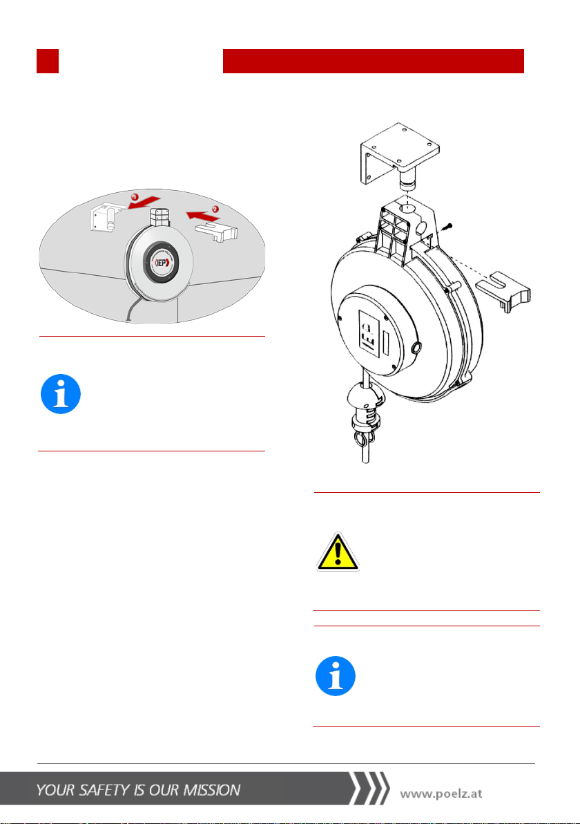
4.2
Mounting the Cable Reel
You can mount the cable reel on a wall or
on the ceiling.
Note!
If mounting the cable reel on
the ceiling, it must
be possible
to swivel it by 360
°; in the ca
se
of mounting on the wall, it
must be possible to swivel it by
150
°.
1. Screw the universal bracket to the wall
or ceiling.
2. Push the cable reel onto the universal
bracket's bolt.
3. Push the slide into the recess on the
universal bracket to secure the cable
reel.
4. Fix the slide using the locking screw.
Danger of injury!
It is crucial to fix the slide using
the locking screw; otherwise,
the cable reel can come loose
and drop off.
Ensure that the locking screw is
screwed tight.
Note!
When mounting the
cable reel,
ensure an optimum pull out
angle to avoid the cable ru
b-
bing against the pull out ope
n-
ing.
4
OPERATING INSTRUCTIONS
Spidy Cable Reel
14
Note!
Observe the maximum moun
t-
ing height of the device of up
to a maximum of 6.30
m (with
the Spidy
ROLLER 230 V, up to
a maximum of 8
m) (see also
Chapter 8.1 TECHNICAL DATA
).
4.3
Connecting the Cable Reel
Depending on the device type, you can
either connect the cable reel directly to
Industrieelektronik Pölz GmbH's battery
testing and charging system (or similar
devices) or to the mains supply.
Connect the pull out cable to Industrie-
elektronik Pölz GmbH's combined socket
on the vehicle or make another connec-
tion to the battery system.
Danger electrical hazard!
Check that the cable reel and
all its cables are in perfect
condition before use.
Caution!
Do not use a cable with a
green and yellow earth wire
with the Spidy ROLLER 12 V /
24 V and Spidy AIRROLLER
12
V / 24 V.
Note!
Industrieelektronik Pölz GmbH
recommend
s using a mainte-
nance unit (comprising an air
filter, a water separator,
a
pressure reducer, a pressure
gauge and a bracket).
You can order maintenance
units from our customer service
(see also Chapter 1.2 CUSTOM-
ER SERVICE)
.
4.3.1
Connecting a Spidy ROLLER
12 V / 24 V (without Com-
pressed Air Supply) to the
Battery Testing and Charging
System
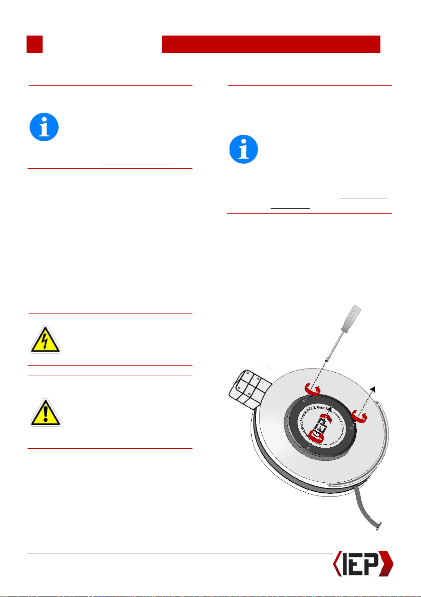
1. Screw the cover off.

4
OPERATING INSTRUCTIONS
Spidy Cable Reel
15
2. Connect the cable reel to Industrie-
elektronik Pölz GmbH's battery testing
and charging system (or similar devic-
es) by connecting the associated wires
according to the graphic below:
3. Screw the cover closed.
4.3.2
Connecting a Spidy ROLLER
12 V / 24 V (with Compressed
Air Supply) to the Battery
Testing and Charging System
1.
Connect the cable reel to the battery
testing and charging system as de-
scribed in Chapter
4.3.1 CONNECTING A
SPIDY ROLLER 12 V/24 V(WITHOUT
COMPRESSED AIR SUPPLY)TO THE BATTERY
TESTING AND CHARGING SYSTEM.
2. Connect the air hose to the com-
pressed air supply system in the vehicle
hall to ensure the supply of com-
pressed air. To do this, proceed as fol-
lows:
3. Release the (blue) coupling ring.
4. Press the coupling ring onto the air
hose.
5. Put on the air hose.
6. Screw the coupling ring tight.
7. Screw the cover closed.
4.3.3
Connecting a Spidy ROLLER
230 V (without Compressed
Air Supply) to the Mains Sup-
ply
1.
Screw off the cover as described in
Chapter
4.3.1 CONNECTING A SPIDY
ROLLER 12 V/24 V(WITHOUT COM-
PRESSED AIR SUPPLY)TO THE BATTERY TEST-
ING AND CHARGING SYSTEM.
2. Loosen the screws of the lustre ter-
minal.
3. Connect the cable reel to the mains
supply as shown in the graphic below:

4
OPERATING INSTRUCTIONS
Spidy Cable Reel
16
•Protective earth (c) = yellow and green
cable with earth wire
•N (neutral conductor) = blue cable (not
fused)
•L1 (wire 1, phase) = brown cable
(fused)
Note!
When connecting, make sure to
connect the yellow and green
cable with the earth wire to the
lustre terminal marked with the
earth symbol
c
and that strain
relief is screwed tight.
4. Tighten the screws of the lustre termi-
nal and strain relief.
5. Screw the cover closed.
4.3.4
Connecting a Spidy ROLLER
230 V (with Compressed Air
Supply) to the Mains Supply
1. Screw off the cover as described in
Chapter
4.3.1 CONNECTING A SPIDY
ROLLER 12 V/24 V(WITHOUT COM-
PRESSED AIR SUPPLY)TO THE BATTERY TEST-
ING AND CHARGING SYSTEM
.
2. Loosen the screws of the lustre termi-
nal.
3. Connect the cable reel to the mains
supply as shown in the graphic below:
•Protective earth (c) = yellow and green
cable with earth wire
•N (neutral conductor) = blue cable (not
fused)
•L1 (wire 1, phase) = brown cable
(fused)
•L2 (wire 2) = black cable

4
OPERATING INSTRUCTIONS
Spidy Cable Reel
17
Note!
When connecting, make sure to
connect the yellow and green
cable with the earth wire to the
lustre terminal marked with the
earth symbol
cand
that strain
relief is screwed tight.
4. Tighten the screws of the lustre termi-
nal and strain relief.
5.
Connect the air hose to the com-
pressed air supply system in the vehicle
hall to ensure the supply of com-
pressed air (see also
ter
4.3.2 CONNECTING A SPIDY ROLLER
12 V/24 V(WITH COMPRESSED AIR SUP-
PLY)TO THE BATTERY TESTING AND CHARG-
ING SYSTEM).
6. Screw the cover closed.
Caution!
When connecting to electric
motors make sure that the
start
-up current does not ex-
ceed about three times the
rated current and 10
A.

5
OPERATING INSTRUCTIONS
Spidy Cable Reel
18
5
Operation
After you have connected the cable reel to
the battery testing and charging system or
the mains supply, it is ready to supply
power and (depending on the device type)
compressed air.
Fire hazard!
When reeled
-
up, the cable can
become very hot in the case of
severe inductive loading.
If under heavy load, pull the
cable out completely.
Caution!
The supplied cables are rated
for normal operation.
Do not overtension the cable
(e.g. by hanging weights from
it).
Do not use force to pull the
cable, since
this damages the
device.
Note!
If supplying of power and co
m-
pressed air does not work,
check the fuses and cables as
well as the air pressure at the
pressure gauge (see also Cha
p-
ters 7.1.1 CHECKING AND REPLAC-
ING FUSES
and
7.1.2 CHECKING
AND REPLACING CABLES
).

6
OPERATING INSTRUCTIONS
Spidy Cable Reel
19
6
Dismantling
Danger, electrical hazard!
Before carrying out any
dis-
mounting work, disconnect the
cable
reel from the mains
su
pply or the battery testing
and charging system.
6.1.1
Dismounting the Cable Reel
Note!
Ensure that all the cable has
been reeled in.
1. Loosen the slide's locking screw to pull
the slide.
2. Pull the cable reel off the universal
bracket's bolt.
3. Take the cable reel out of the universal
bracket.
4. Take the cable reel off the wall or
ceiling.
Danger of dropping!
Take the cable reel off the wall
or ceiling before starting any
servicing work.

7
OPERATING INSTRUCTIONS
Spidy Cable Reel
20
7
Service
Danger!
Servicing work must only be
carried out by qualified people
who have been tasked with this
work.
Danger, electrical hazard!
Before carrying out any servi
c-
ing work, disconnect the cable
reel from the main
s supply or
the battery testing and char
g-
ing system.
Danger of dropping!
Take the cable reel off the wall
or ceiling before starting any
servicing work.
7.1
Maintenance
Note!
The cable reel is maintenance
-
free.
7.1.1
Checking and Replacing Fuses
1. Screw off the cover as described in
Chapter
4.3.1 CONNECTING A SPIDY
ROLLER 12 V/24 V(WITHOUT COM-
PRESSED AIR SUPPLY)TO THE BATTERY TEST-
ING AND CHARGING SYSTEM
.
2. Remove the fuse holder.
3. Take the fuse out of the fuse holder
and replace it if necessary.
4. Press the new fuse into the fuse hold-
er.
Note!
Use only fuses rated at 10 A
(slow blow).
5. Push the fuse into the fuse holder.
6. Screw the cover closed.
This manual suits for next models
3
Table of contents
Other IEP Tools manuals


