Sealey GA40 User manual

INSTRUCTIONS FOR:
OPTICAL ALIGNMENT GAUGE
Model No: GA40
Thank you for purchasing a Sealey product. Manufactured to a high standard this product will, if used according to these instructions
and properly maintained, give you years of trouble free performance.
GA40 - 1 - 080304
1. SAFETY INSTRUCTIONS
IMPORTANT: PLEASE READ THESE INSTRUCTIONS CAREFULLY. NOTE THE SAFE OPERATIONAL REQUIREMENTS, WARNINGS & CAUTIONS.
USE THE PRODUCT CORRECTLY AND WITH CARE FOR THE PURPOSE FOR WHICH IT IS INTENDED. FAILURE TO DO SO MAY CAUSE
DAMAGE AND/OR PERSONAL INJURY AND WILL INVALIDATE THE WARRANTY. PLEASE KEEP INSTRUCTIONS SAFE FOR FUTURE USE.
1.1 GENERAL SAFETY
pWARNING! Ensure Health & Safety, local authority, and general workshop practice regulations are adhered to when using this equipment.
3Maintain the gauge in good condition (use an authorised service agent).
3Replace or repair damaged parts. Use genuine parts only. Unathorised parts may be dangerous and will invalidate the warranty.
3Locate gauge in a suitable working area, keep area clean and tidy and free from unrelated materials.
pWARNING! Use gauge on level and solid ground.
3Keep the gauge clean to ensure accurate performance.
7DO NOT use outside in damp or wet weather conditions.
7DO NOT allow untrained persons to operate the gauge.
7DO NOT leave the gauge unattended.
pWARNING! When setting front end alignment on commercial vehicles never make adjustments to drop arms or interconnecting links. Doing
so could result in serious tyre, wheel and steering problems.
3Any alignment changes deemed necessary as a result of using this equipment must be made strictly in accordance with the vehicle
manufacturers recommendations.
2. INTRODUCTION & SPECIFICATION
Steel and cast aluminium construction.
Measures toe-in and toe-out by contact with wheel rims and using optical sight to align markers.
Works on practically all cars and light commercial vehicles with rim diameters between 200mm and 600mm.
3.1. ASSEMBLY. Your gauge has been supplied in flat pack form for quick and easy assembly.
3.1.1 Take each ready assembled side frame in turn and slide on the balance leg (fig.1.8). Slide the balance leg back onto the alignment peg
and tighten the thumbscrew.
3.1.2 Place the two frames opposite each other with each extended bar portion positioned to the right hand side. The frame nearest to you is
the one to which the periscope (fig. 1.3.) unit should be attached.
3.1.3 Place the periscope unit onto the tube and slide it to the left until it stops against the end of the tube. Tighten the two thumb screws on
the back of the unit to secure it to the main bar. Attach the target plate (fig. 1.4.) to the periscope using the screws supplied.
3.1.4 Slip the mirror unit (fig. 1.2.) onto the main bar of the other frame and tighten the thumb screw to secure it.
3.1.5 Attach a contact bar (fig. 1.1.) to each of the upright arms. Firstly loosen the thumb screw on the contact bar holder and place through
the upright arm. Slide the square portion of a contact bar through the holder, tighten the thumbscrew to secure.
3.1.6 Each contact bar may be fitted either to the left or the right of its respective support arm. This is to allow the gauge to handle all tyres
on 8 to 24 diameter rims and to allow close contact when required e.g. when in use on a vehicle lift.
3.2. CALIBRATION. The gauge will be calibrated each time it is used as part of the process of checking wheel alignment. Calibration will be
done with the two halves of the gauge facing each other with the contact bars touching.
3. ASSEMBLY & CALIBRATION
Fig. 1. Fig. 2.

4. OPERATING THE GAUGE - CARS & VANS
NOTE: CARS & VANS. Prior to use check vehicle manufacturers recommendations relating to loading. Check that tyre pressures are correct.
4.1. Ensure that the vehicle is on a smooth level surface with the wheels pointing straight ahead. Do not back the vehicle into position.
4.2. Position the periscope unit against the offside front wheel ( see fig. 3 ) and adjust the height of the contact bars by fixing them in which
ever of the five preset positions is closest to a horizontal line through the centre of the wheel. At the same time adjust the side to side
positioning of the contact bars so that they touch the sidewall of the tyre either side of the rim. Position the tips of the contact bars to
touch the centre of the sidewalls at the greatest point of curvature. Avoid any ribs or raised lettering on the tyre side wall.
3.2.1 Stand the complete gauge on a level, clean floor with contact bars touching as in fig. 1.
3.2.2 Adjust the mirror and periscope until the reflection of the target plate (fig. 1.4.) is visible through the periscope.
3.2.3. Sighting through the periscope move the pointer (fig. 1.5.) until the image reflects the hair line in the centre of the triangle between the
vertical lines as in (fig. 2.).
3.2.4. The pointer should now be at zero on the graduated scale (fig. 1.6.). If not slacken the two wing nuts holding the scale, adjust the
scale to zero and tighten the wing nuts. The gauge is now ready for use.
4.3. The contact bars of the mirror unit should now be set up to the same height and width as
the periscope unit. To do this remove the periscope unit from its position on the tyre and
place it in front of the mirror unit to make the necessary adjustments.
4.4. When the contact bar arrangements on both units match, proceed to calibrate the gauge.
( See calibration set - up 3.2.1 to 3.2.4. )
4.5. Set up both units as in (fig. 4.). Looking through the periscope adjust the pointer until the
hair line bisects the triangle between the two vertical lines.(fig. 2.) The amount of toe-in or
toe-out can now be read from the scale (fig. 6.) in degrees and minutes.
4.6. To allow for any possible lateral run out of the wheels and tyres the vehicle should be
moved forward until the wheels have rotated half a revolution (1800) and the operation
repeated. If a different reading is obtained the two results should be averaged.
4.7. The calculator (fig. 1.7.) allows conversion of the angle obtained to a linear measurement
in millimetres or fractions of an inch (Linear toe in or toe out). Set the large arrow on the
top dial to the specified width on the bottom dial. The specified width may either be the
nominal wheel diameter or a dimension equivalent to a diameter to the tyre sidewall e.g.
mid sidewall (or in accordance with the measuring position figures in the appropriate
workshop manual or handbook). Read the linear toe reading from the bottom dial,
opposite the angular toe reading from the top dial.
4.8. Any alignment necessary must be made strictly in accordance with the vehicle
manufacturers recommendations.
Fig. 3.
Fig. 4.
NOTE: COMMERCIAL VEHICLES. The gauge is also designed to check wheel alignment on two, three or four axle vehicles. Before using
the gauge, the vehicle manufacturers recommendations in respect of loading, tyre pressures etc must be complied with. In the
absence of definite instructions, it is normal practice to check commercial vehicles when fully laden and with all wheels parallel.
When setting front end alignment, never make adjustments to drop arms or interconnecting links. Doing so could result in
serious tyre, wheel and steering problems.
5.1 Single Steering Axle : Procedure is the same as for cars and vans.
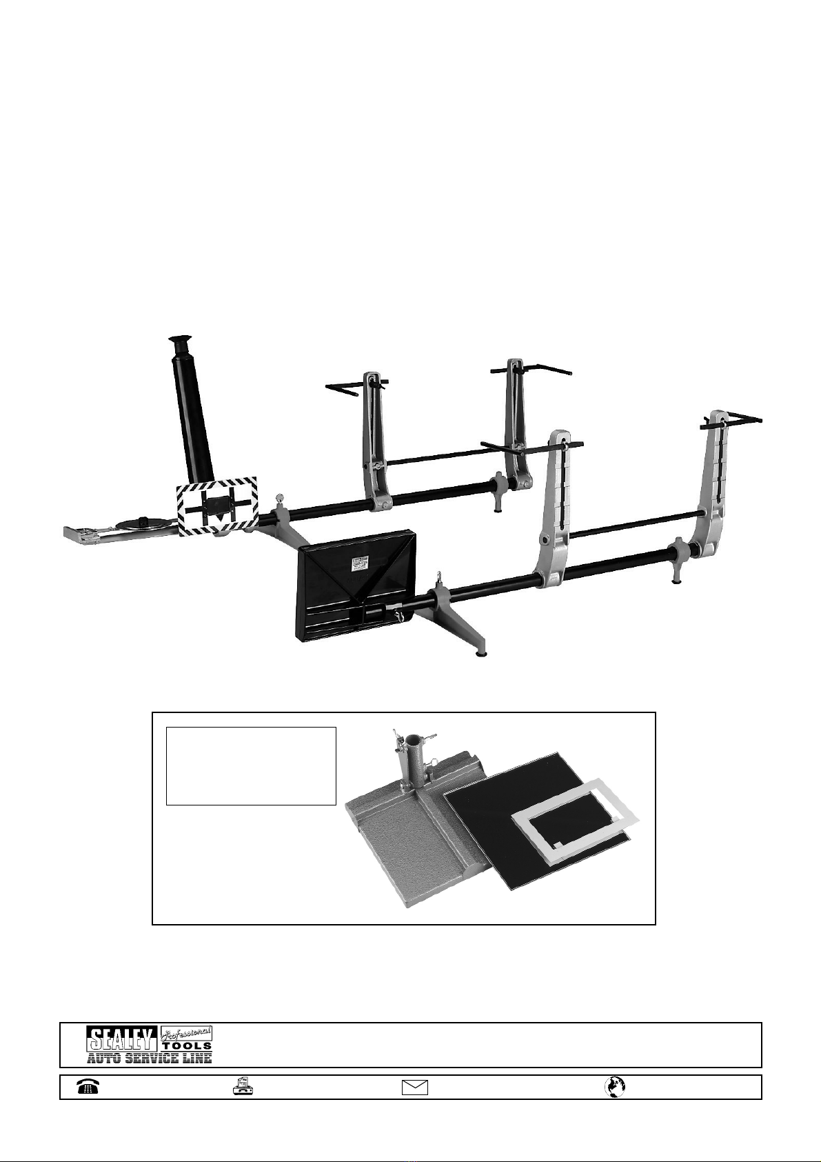
5.2 Twin Steering Axles : When checking wheel alignment on twin steering vehicles you will also need to use the optional equipment
package comprising larger mirror and frame. Order Item: GA43
5. OPERATING THE GAUGE - COMMERCIAL VEHICLES
Fig. 5.
GA40 - 1 - 080304
Sole UK Distributor, Sealey Group,
Bury St. Edmunds, Suffolk.
NOTE: It is our policy to continually improve products and as such we reserve the right to alter data, specifications and component parts without prior notice.
IMPORTANT: No liability is accepted for incorrect use of this product.
WARRANTY: Guarantee is 12 months from purchase date, proof of which will be required for any claim.
INFORMATION:
For a copy of our latest catalogue and promotions call us on 01284 757525 and leave your full name and address, including
postcode.
01284 757500 sales@sealey.co.uk www.sealey.co.uk
01284 703534 e-mail Web
5.2.3 Stand the periscope unit on a level floor approximately 1metre ahead of the front bumper with the target plate facing the mirror. This is
the set up shown in fig.5. With the pointer at zero, move the periscope unit until the hair line bisects the triangle as in fig. 2.
5.2.4 Without moving the periscope unit, transfer the mirror unit to the next axle ( X in fig.5 ) and check the reading. This should be identical
to axle Y. If not then the rear axles are not parallel and will require adjustment.
5.2.5 Position mirror unit at axle A and check reading. If the original setting was parallel, the hair line should be central on the target plate.
For a toe in setting, move the pointer until it shows half the amount of the recommended toe-in ( e.g. a 20 movement for a 40 toe-in
).
The hair line should now be in the central position on the target plate. If not, gently turn the steering wheel, keeping the contact bars
positioned on the rim or the tyre sidewall until the hair line is central. Axle A is now correctly aligned with the rear axles.
5.2.6 Move the mirror unit to axle B and note the reading in comparison to axle A.
5.2.7 If the reading is different the inter-axle adjuster will need adjustment, recheck from step 5.2.2 onwards.
5.2.8 To compensate for run-out in tyres and/or wheels roll the vehicle forward until the wheels have rotated half a revolution (1800). Repeat
steps 5.2.2 to 5.2.6. Should the results vary, average the figures obtained. Adjust the connecting rods as necessary until the hair line
appears central.
5.2.1 Check alignment of the two pairs of front axle wheels ( A & B in fig.5 ) in the same way as you would for cars including the calibration
procedure. Adjust if required to the manufacturers recommendations or set to parallel.
5.2.2 Replace normal mirror unit with the larger mirror unit. Place this unit against the last axle ( Y in fig.5 ) with the mirror orientated towards
the front of the vehicle.
GA40 - 1 - 080304
Optional equipment consisting of
a larger size mirror and a target
plate enlargement frame.
Order Item: GA43
Table of contents
Other Sealey Tools manuals

Sealey
Sealey RS13 User manual

Sealey
Sealey SM94.V3 User manual

Sealey
Sealey VS9112 User manual

Sealey
Sealey HRCHD User manual

Sealey
Sealey BSL103 User manual

Sealey
Sealey VS2386 User manual

Sealey
Sealey PS990 User manual

Sealey
Sealey TC904 User manual

Sealey
Sealey VS0205.V2 User manual

Sealey
Sealey Power tools GSA11 User manual

Sealey
Sealey AK962EV.V2 User manual

Sealey
Sealey SUPERSNAP RE83/10/SK User manual

Sealey
Sealey VSE127H05 User manual

Sealey
Sealey VS7233 User manual

Sealey
Sealey PS983.V2 User manual

Sealey
Sealey SA51 User manual

Sealey
Sealey CPG18V.V3 User manual

Sealey
Sealey Auto Service VS2046.V2 User manual

Sealey
Sealey PS990.V2 User manual

Sealey
Sealey VS919 User manual


