iFactory3D One Pro User manual

_97971.01
Assembly instructions - Aufbauanleitung
iFactory3D One Pro
Language
ENG Page 2
DE Page 20
Check for updated versions of the assembly instructions on https://ifactory3d.com/instruction-
manuals/
Die neueste Version der Anleitung kann hier abgerufen werden: https://ifactory3d.com/instruction-
manuals/

V_97971.01
2
ENG
General Information
Read the instructions carefully. By using the machine, you confirm to have
read the assembly instructions as well as safety, maintenance and warranty
advise!
Safety advises
Unintended use and wrong handling can lead to machine fault.
The machine can only be used or cleaned or maintained by instructed persons.
Intended use just includes 3D-Printing (additive manufacturing) of polymer parts with appropriate material (filament).
Outdoor use is not recommended. Use only at own risk.
Avoid contact between the device and any liquid.
Always pull the power plug when the machine is not in use or before cleaning/maintaining.
Power cable is not allowed to touch hot, moving or sharp objects.
Do not use the machine if:
o The power plug or cable are damaged.
o The device might have taken damage from falling or other reasons.
Do not open the electronics case, especially not the power supply unit.
The device must be used on a flat surface, which is large enough for the whole machine to fit on.
This surface must be heat resistant and able to handle vibrations.
Make sure no flammable objects can get in contact with the machine.
Careful!
Printhead and printbed / belt area as well as surrounding parts will be hot during use. Do not touch!
Belts driving the printhead and the main belt will move while printing or operating. Do not touch!
Do not move the device during use.

V_97971.01
3
Maintenance
Check the quality of the produced parts regularly.
Nozzle and belt will wear down while printing.
We recommend changing the nozzle after constant use. The reasonable frequency highly depends on the used materials abrasiveness.
The nozzle should be changed as soon as you notice the extrusion width exceeds its original size by far.
We have been able to still achieve good results after more than one month of constant printing with iFactory3D brass nozzle and
iFactory3D PETG filaments.
Non-hardened brass nozzles wear faster than hardened nozzles especially when using filaments with high abrasiveness, such as plaster or
reinforced filaments.
The belt usually lasts between 6 - 12 months of constant printing if the whole belt width is used. Try varying the placing of objects in the
slicer to use the whole width of the belt evenly to increase its lifetime.
The belt might be stained after printing with some materials but it can still be printed on these areas.
Change the belt when it’s been heavily roughened and fibers stand out clearly or parts of it have melted.
Check the friction of the linear rails holding the printhead regularly.
For relubricating, check the instructions:
https://www.hiwin.us/wp-content/uploads/lubricating_instructions.pdf
for MGN12 linear rails.
Use supported lubricants only.
Warranty
Perform all maintenance instructions regularly. There is no warranty on parts listed in maintenance section caused by skipping
maintenance schedule or normal wear.
If you perform any software changes unauthorized by iFactory3D, we cannot provide any support for software related issues.
Opening the power supply unit or changing parts of the electronics will also lead to a loss of warranty.
Do not use any software which is not officially tested by iFactory3D.
Do not exchange parts of the machine with different parts that have not been tested before by iFactory3D.
Only use genuine iFactory3D parts for this machine.
Changing the machine by exchanging parts or somehow mechanically machining them will lead to a loss of warranty for all changed parts
and all damages caused by these changes.

V_97971.01
4
A testprint has been performed on your machine before shipping.
Any traces of filament on the nozzle/heatblock or marks on the belt are caused by a single short
testprint performed by us to check the quality and settings of the machines.
Note: Some assembly groups are attached to each other via cables.
Remove them from the packaging material carefully to not stress or bend the cables.
The One Pro comes with a unique serial number on the right side next to the power input.
For any support questions or problems with your machine make sure to have the serial number
ready.

V_97971.01
5
Parts included
Please check if all listed parts are included before starting to assemble the machine.
If there are damaged or missing parts, contact [email protected] immediately.
ASM-Group1:
This group contains electronics, display and the belt.
ASM-Group2 and the Raspberry-Pi camera are attached to AMS-Group1 via cable.

V_97971.01
6
ASM-Group2:
This group contains printhead and gantry.
Do not tension gt2-belts before the machine is fully assembled.
ASM-Group3:
This group contains a 2040-Extrusion with the filament runout sensor.

V_97971.01
7
ASM-Group4:
This group only contains one 2040 extrusion.
Other parts:
Cam-clip x3
Allen keys 1.5; 2; 2.5; 3 and 4 [mm]
Wrench 13 mm for M8 nuts (belt rollers)
Wrench 5.5 mm for M3 nuts
Power cable
Clip for coupler
Screws & nuts:
o M5x30 4x
o M5x20 6x
o M5x8 2x
o M4x18 4x
o M4x8 5x
o M4 slot nut 5x (+ one spare)

V_97971.01
8
Assembly
Step 1:
Place AMS-Group1 on a flat surface. Make sure the cable connecting ASM-Group1 and ASM-Group2
is not tensioned.
Now place ASM-Group3 (profile with filament runout sensor) onto the front right foot in a 45° angle.
The filament sensor should point inwards.
Use two M5x20 screws to secure the profile to the foot.
Use two M4x8 screws and two M4 slot nuts to attach the profile to the display.
Note: Slot nuts need to be inserted into the slot of the profile before positioning them:

V_97971.01
9
Step 2:
Mount ASM-Group4 to the front left foot:
Make sure that the sinkings on the top end of the profile are pointing to the outside.
Use two M5x20 screws.
V_97971.01
10
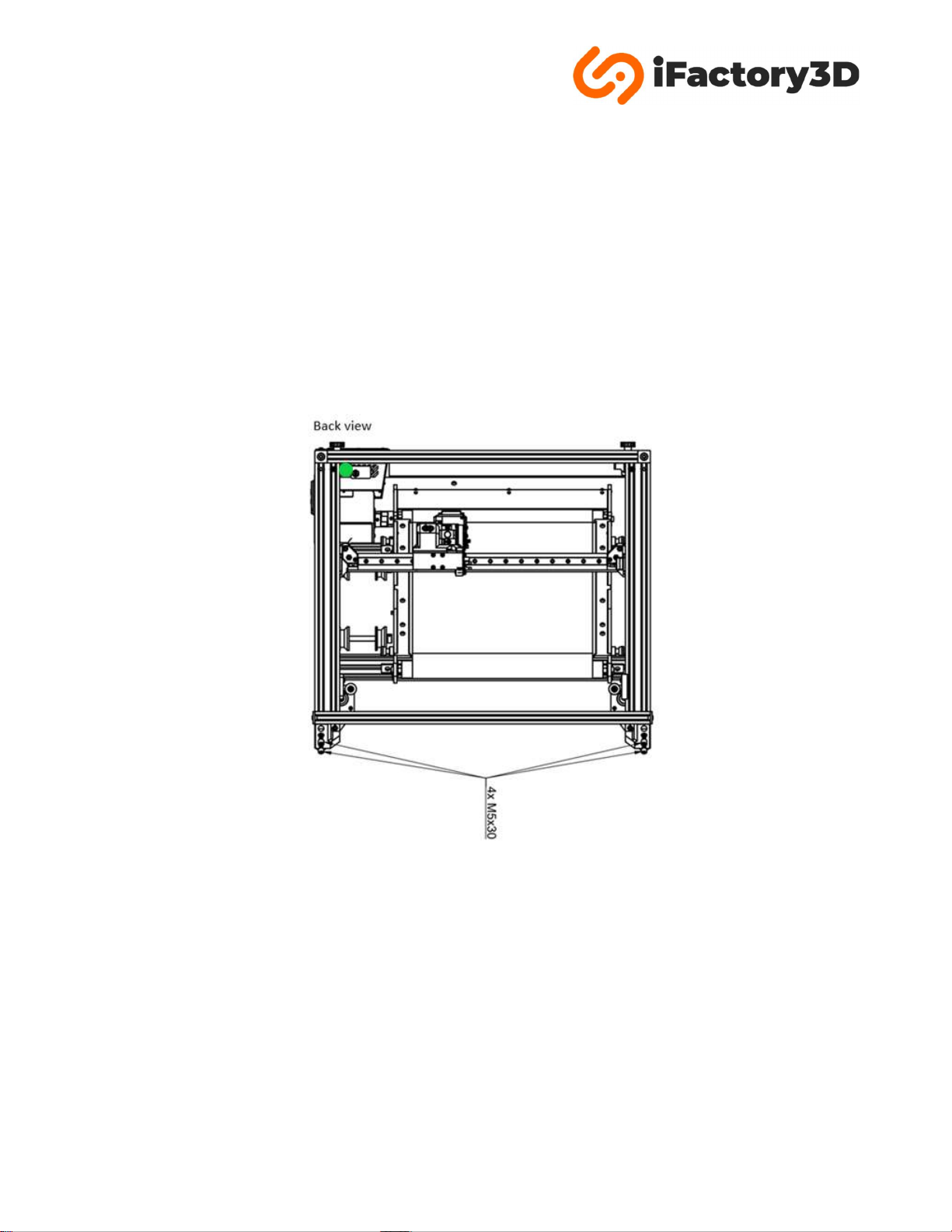
Step 3:
Mount ASM-Group2 on the end of the back profiles of ASM-Group1:
The corner cubes and gt2-tensioning system should point upwards.
Back feet of ASM-Group2 should point downwards.
The cable connecting the printhead with ASM-Group1 must be placed beside the filament runout
bracket from ASM-Group3:
Use four M5x30 screws for the back feet of ASM-Group2.
Other manuals for One Pro
1
Table of contents
Languages:
Other iFactory3D 3D Printer manuals


