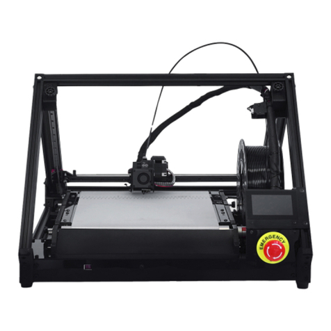
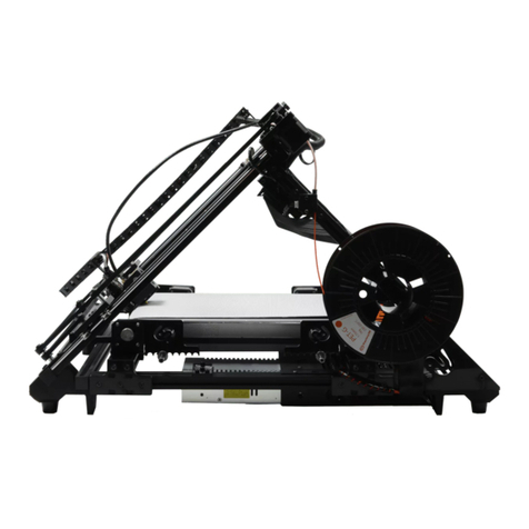
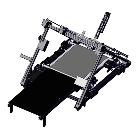
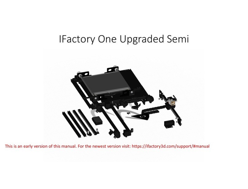
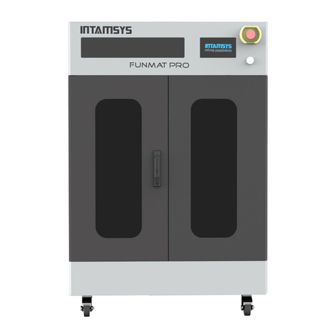
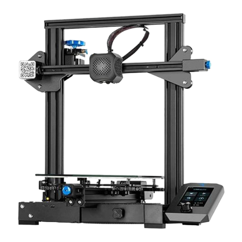
iFactory3D One User manual

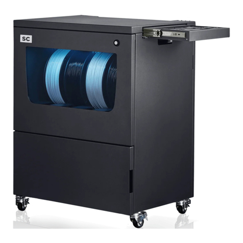
iFactory One Semi
Disclaimer: This is an early version of this manual. For the newest version visit: https://ifactory3d.com/support/#manual

General advice
For the assembly of many components of the iFactory
One, so-called T-nuts are used. The T-nuts need to be
pushed into the profiles groove. This only works if the
T-nut is in the correct position, as shown in the
picture.

General advice
Once the T-nut is in the groove and the component is
in place, the screw can be tightened. To create the
desired clamping, the T-nut must be turned 90° as
shown in the picture.
There might be the case that the T-nut does not turn
in the groove when the screw gets tightened. If this
happens, you should turn the screw back a little (do
not turn the screw all the way out because then you
will lose the nut!) and then tighten it again until the
T-nut produces the desired clamping.
In general, screws in plastic components should not
be tightened too much, otherwise those might break
(as soon as you hear noises, do not continue turning).

Step1
Mounting of the back feet
Belt group
First, the feet must be attached to the pre-
assembled belt assembly. The rear feet are
already attached
to an aluminium profile and will be mounted on
the back of the belt assembly as shown in the
picture.
The easiest way to mount the feet is to lay the
belt assembly on its side and tighten the pre-
assembled
M4x14 screws in the feet from below. The rear
feet must be placed so that they touch the
underside of the rear tensioning guides.
Back feet

Step 2
Mounting of the front feet
The front feet will be mounted on the front 20x20
profile and are attached in the same way as the back
feet.
The 45°chamfer is pointing inwards.
Foot LF Foot RF

Step 3
Mounting the guide rails
The guide profiles are mounted with the small roller
holders to the aluminium profile of the back feet.
For this purpose, the T-nuts of the roller holders are
used.
Guide rails

Step 4
Printhead
The guide profile of the print head is pushed over the
metal rails with the pre-assembled large roller
holders. The print head must be aligned so that the
nozzle of the printhead points in the direction of
the belt. If the printhead guide rail has been pushed
correctly, [roller holder large R] is now on the same
rail as the [roller holder small L].
Printhead

Step 5
Attaching the 20x20x460 profiles
Now the 20x20x460 profile with the pre-
assembled angles must be mounted to the
front
feet (attention: angles are attached to the
profile and are not used to attach the profiles
to the feet).
Mount the profiles on the 45° side of the feet
so that the angles on the profiles point
upwards. Attach the other side of the
20x20x460 profile to the guide rail.
Use M5x25 screws for this step.
20x20x460 Profile

Step 6
Mounting of the motor profile
Please note the orientation of the motors as shown
in the picture. Mount the profile on the angles from
the previous step.
Motors with profile

Step 7
Adjusting the motors
Now loosen the M4 (lower) screws in the X- and Y-
plates.
Then slide the plates inwards as shown in the
illustration until the side T-nuts are in the recesses of
the 20x20x460 profile (mounted in Step 5).

Step 8
Securing the motors
After the motors are placed, tighten the circled screws and
screw in a M5x25 screw as indicated in the picture.
Do this step for the Y- as well as for the X-motor.

Step 8.5
Aligning the wheels
Check, if the printhead moves smoothly upwards and
downwards. If it does, go to Step 9.
If the printhead rail does not move smoothly, do the
following steps:
The wheels that should be adjusted are the eccentric
wheels - indicated with arrows in the picture.

Step 8.5
Aligning the wheels
First, loosen the set screws (no need to do it as far as
in the picture but just a little bit).
Try loosening the bolt on the other side of the wheel.

Step 8.5
Aligning the wheels
You can fasten the bolt again, when you have placed
the X-rail onto the frame. Fastening the bolt
automatically realigns the wheel (it rotates along
with the bolt until the wheel hits the rail). Then
fasten the set screws.
If the bolt does not really want to come loose, you
can try to turn the disc with the eccentric bore. This
may require some force if the bolt is firmly fastened.

Step 9
Placing the Y-belt
The next step is best done from the back of the
printer. Place the gt2 belt over the Y-stepper
motor pulley and then along all the other pulleys
on the back - as shown in the picture - to build a
core XY-motion system. Mount the belt to the
printhead with a cable tie. Do not tension the belt
too much, just avoid any sagging.

Step 10
Placing the X-belt
Place the gt2 belt over the X-stepper motor pulley
and then along all the other top pulleys on the back
as shown in the picture to build a core XY motion
system. Mount the belt to the printhead with a cable
tie.
Do not tension the belt too much, just prevent any
sagging.

Step 11
Tightening the X- and Y-belts
Release the four M3 screws in each motorplate.
Pull the motors upwards as shown in the picture and
tighten the M3 screws again.
If the belt is not tensioned enough, release the four
M3 screws again and repeat Step 20 and 21, but this
time with more tension applied to the belts.
If the belts are tight enough, you can cut off the
remaining gt2 belt at the printhead.

Step 12
Side bracket
Side bracket
Mount the corner brackets with the logo on the front
outer corners.

Step 13
Belt and tightening
Pull the two back belt tightening sliders as far as
possible to the back and tighten the M4 screws.
Pull the two front belt tightening sliders in the
direction of the side plates with the iFactory3D logo
and fasten the sliders as soon as they hit the side
plates*.
* For all early versions of the printers, there are still smaller side plates, so an equal air gap of around 7mm between side plate and sliders
is needed.

Step 14
Rods and tightening
8mm rod
Now place the two 8mm rods through the belt and
the underside of the square bar and clip it into the
fitting of the bearing brackets.
The fittings are numbered, and the rods need to be
at the same number to apply the tension evenly to
the belt.
The higher the number of the fitting, the more
tension is applied to the belt.
This manual suits for next models
1
Table of contents
Other iFactory3D 3D Printer manuals
