ReDeTec ProtoCycler+ User manual
User Manual
Rev 2.0

Table of Contents
1.0 Introduction to the ProtoCycler+ 3
1.1 Safety 3
1.1.1 General Safety 3
1.1.2 Extrusion Safety 3
1.2 ProtoCycler+ Layout 4
2.0 Grinding 6
2.1 Grinder Operation 6
2.1.1 Grinder Safety 6
2.1.2 Grinder First Time Setup 6
2.1.3 Operation 7
2.2 Sorting Ground Material 7
2.3 Ground Material Size & Extruding Recycled Plastic 8
3.0 Important Things to Know Before Extruding 9
3.1 Puller Wheel Storage 9
3.2 Cleanliness 9
3.3 Plastic Care: Dry vs Wet - Clean vs Dirty 10
3.4 Opaque vs Transparent Plastic 11
3.5 Spooler Set Up 11
3.5.1 Spooler Assembly Instructions 16
3.6 Light Guide Alignment 17
3.6.2 Light Guide Alignment Overview: 18
3.6.3 Step 1 - Adjusting the sensor height 19
3.6.4 Step 2 - Evenly lighting the sensor 20
3.6.5 Step 3 - Calibrating the readings 21
4.0 Extrusion Operational Instructions 23
4.1 Overview 23
4.2 Initial Extrusion Steps for both Manual and Automatic: 23
4.3 Automatic Extrusion 24
4.3.1 Automatic Extrusion Steps 24
4.3.2 Diameter Sensor Check 26
4.4 Manual Extrusion 28
4.4.1 Manual Extrusion Steps 28
5.0 Intro to the ProtoCycler+ Purge Procedure (PPP) 30
5.1 Purging 30
5.1.1 Short Purge 30
5.1.2 Disco Purge 31
5.2 Purge Tips 31
1

1.0 Introduction to the ProtoCycler+
Welcome to the ProtoCycler+ community! The team here at ReDeTec is excited that you have
chosen to walk the path of sustainable 3D printing! We’re here to ensure your success with your
device. Operating the device requires a knowledge base and it is strongly recommended that
you read this entire manual before use.
Upon completion, you will know your way around the device, understand its key limitations, and
be able to operate in both automatic and manual extrusion modes. Most importantly, you will be
able to operate it safely.
If the manual doesn’t cover what you’re looking to understand, or raises further questions,
please visit: www.redetec.com/support
Please consider the environment before printing any copies of this manual.
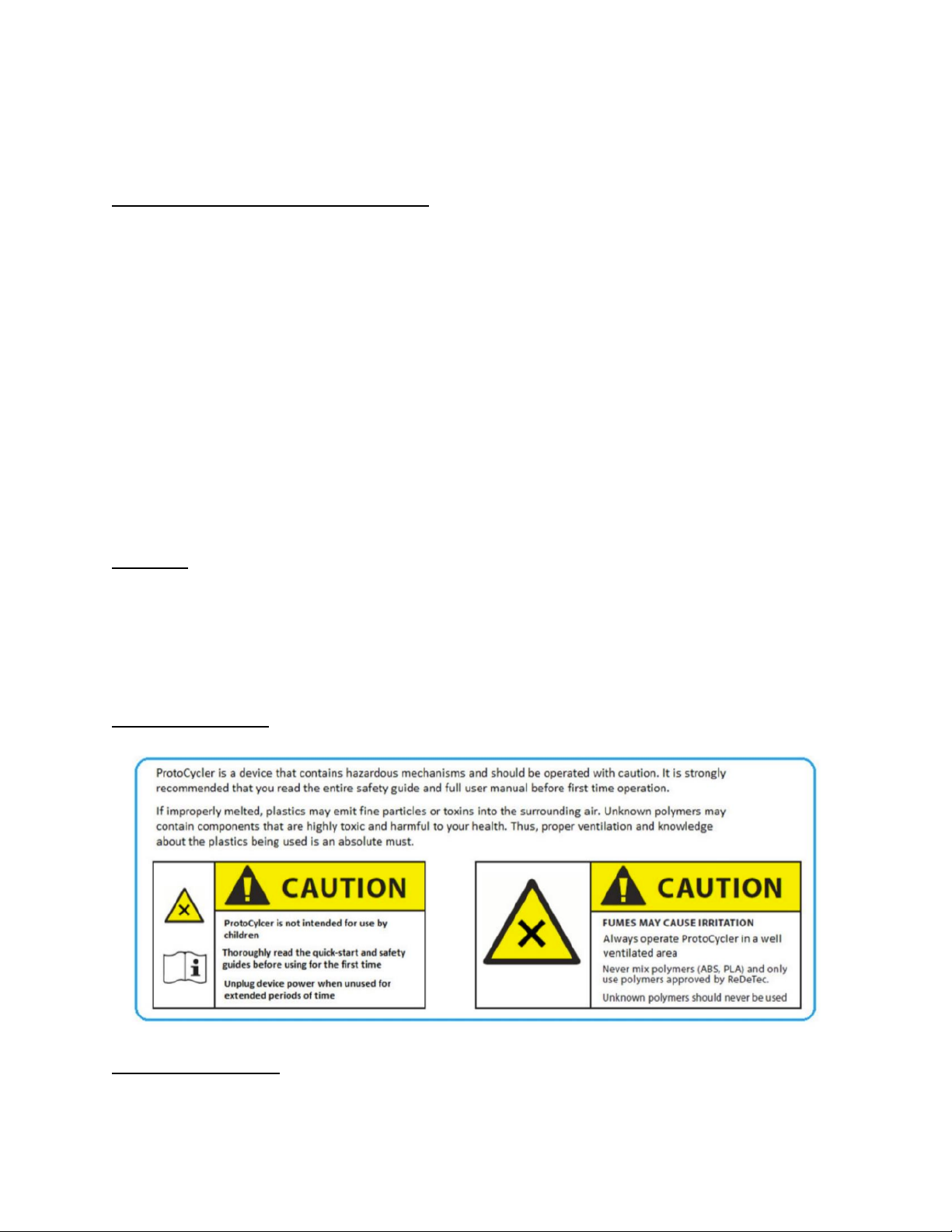
1.1 Safety
Please do not compromise safety for anything. ProtoCycler+ brings industrial grade technology
to the desktop, and should be fully understood before operation. Please thoroughly review the
safety precautions before operating your device. Failure to do so may result in damage to
your device or may cause bodily harm.
1.1.1 General Safety
1.1.2 Extrusion Safety
3

Note: If you have a High Temperature model, temperatures may reach as high as 500°C!
Never extrude PVC or any unknown plastic. The fumes could be lethal! ProtoCycler+
currently supports PLA, ABS, HDPE*, LDPE*, PA12, PETG, HIPS (*special printing hardware is
required to print HDPE/LDPE).
The device provides the ability to experiment with new materials and colors via the manual
extrusion mode. Please do not attempt to extrude any unknown materials unless you
understand the chemical reaction that occurs when the material is thermally broken down. For
example, PVC releases chlorine gas and under no circumstances should you try to extrude it
with the ProtoCycler+.
Always ensure proper ventilation when extruding any plastic, from the supported list or
otherwise.
1.2 ProtoCycler+ Layout
Before we dive in any further, let’s learn the basic anatomy and terminology used for the device.
The following images label the key features.
4

Figure 1: ProtoCycler+ Front View (labeled)
Figure 2: ProtoCycler+ Side Views (labeled)
Figure 3: ProtoCycler+ Inside View (labeled)
Figure 4: From left to right - Nozzle Screen, Nozzle Breaker Plate, Nozzle Cap
5
2.0 Grinding
(skip over this section if you have a Grinderless Unit)
2.1 Grinder Operation
The ProtoCycler+ must be powered on at all times to operate the grinder. The grinder
relies on an electromagnet interlock that engages the grinder drive train only when supplied with
power. The electromagnet is calibrated to disengage the interlock at set torque limit value to
prevent damage to the gear train. The grinder will only work if the two interlock switches are
engaged while the unit is powered on. One switch is engaged by the grinder lid, and the other
by the grinder drawer.
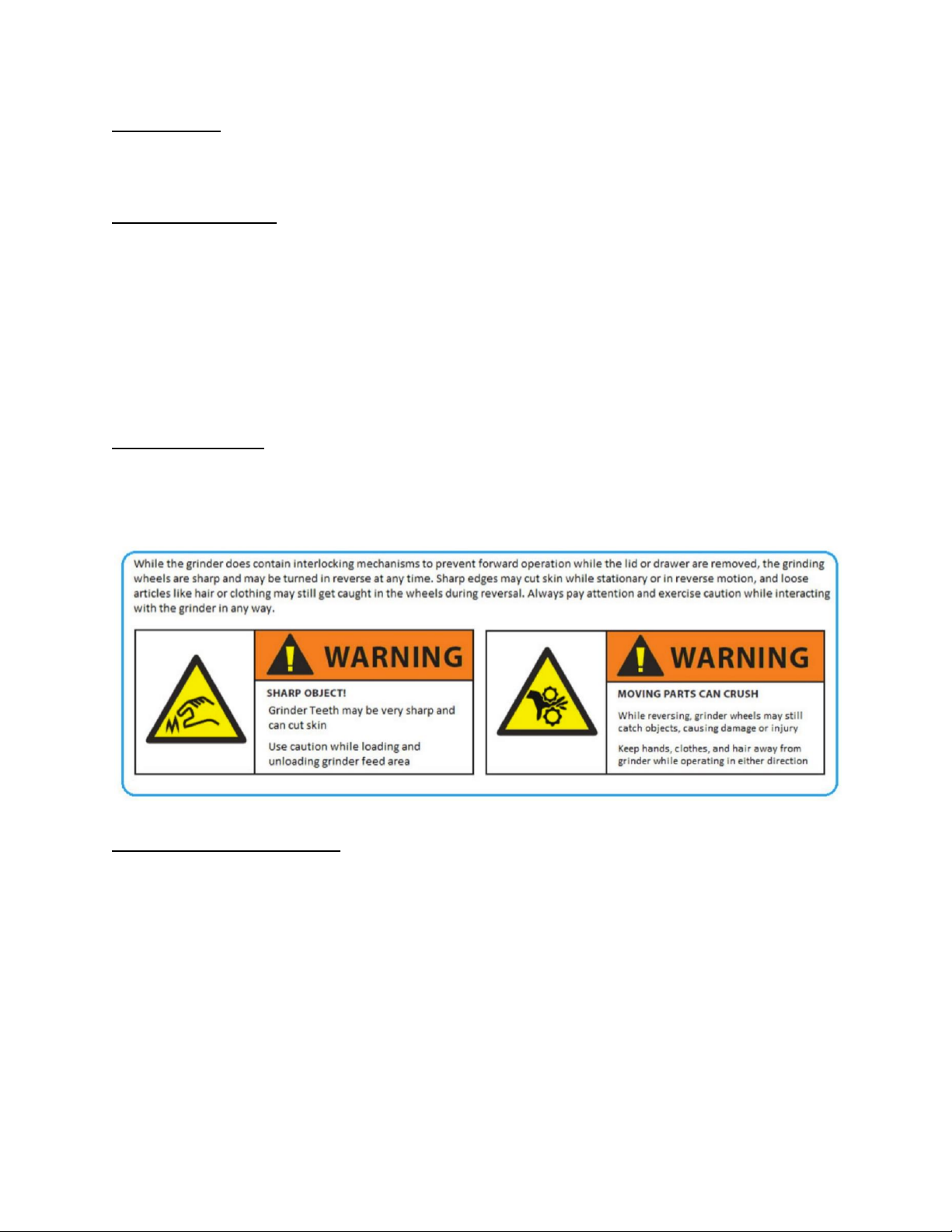
2.1.1 Grinder Safety
Please thoroughly review the safety precautions before operating the grinder. Failure to
do so may result in serious injury or irreparable damage to your device.
2.1.2 Grinder First Time Setup
Installing the Grinder Handle:
1. Remove the Grinder Crank Arm and Allen Key from the Accessories Box.
2. Use the Allen Key to remove the screw and washer from the Grinder Crank.
3. Place the support washer onto the crankshaft.
4. Install the Crank Arm over the hex on the Grinder Crank with the handle facing outwards
Note: the hex size is 5/16”.
5. Replace the screw with the washer under it, and tighten until snug.
Grinder Drawer Preparation:
1. Remove the Grinder Drawer from the side of the ProtoCycler+
6

2. Uninstall the Grinder Sorter from the drawer in preparation for use.
3. Insert the now empty Grinder Drawer back into your ProtoCycler+ in preparation for use.
Note: the Grinder Sorter should never be installed in the Grinder Drawer when
operating the Grinder as this could cause plastic build-up and jamming. The
Grinder Sorter should only be installed in the Grinder Drawer for sorting ground
material
2.1.3 Operation
Note: It is not advised to operate the Grinder while the Extruder is running. Grinder
operation may shift or vibrate the unit which may affect filament quality.
1. Power on your ProtoCycler+
2. Remove the Grinder Lid and place the part you wish to grind into the grinder hopper.
Place the lid back in the hopper. The lid and drawer must be correctly installed in order
to operate the Grinder. While the lid only needs to be partially in, the drawer must
be fully seated against the back wall. Particulates may block this, and so it is
necessary to make sure the drawer slot is clean of debris before reinserting the
drawer.
3. To grind, first rotate the Grinder Handle counter-clockwise to ensure the interlock is
engaged. Then press down on the Grinder Lid Plunger and rotate the Grinder Handle
clockwise. Viewing through the clear area of the Grinder Lid, you will see the Grinder
Teeth spin inwards.
4. During operation, if at any time the load on the grinder teeth exceeds the maximum, the
Grinder Interlock will disengage. Reverse the grinder all the way until the part is pulled
off of the teeth by the clearers, and then attempt grinding again. If unsuccessful, you
may need to fully remove the part and reduce its size by other means, or otherwise
reduce the number of parts you are grinding at one time.
5. When you are done grinding, remove the Grinder Drawer to retrieve the ground material.
Sort the particulates and re-grind the oversized bits. See the following section on sorting
ground material for extrusion.
2.2 Sorting Ground Material
Depending on the material type, density and shape, it may be necessary to sort the ground
material using the provided sorting mechanism. The Grinder Sorter is a liner comprising two
levels of offset holes which are used to sift through the ground material and only allows ground
material of appropriate extrusion size through.
1. Read section 2.3 on desired ground material size.
2. Install the Grinder Sorter into the Grinder Drawer
3. Lift the sorting mechanism most of the way out of the drawer, and hold it so they are still
overlapping.
7

4. Shake the two side to side, up and down, until it seems the only particles left in the sorter
are too large to fall through.
5. You may also wish to shake the sorter over a large pan or bucket to allow a little more
freedom of motion. Make sure whatever you choose for your “catch container” is clean of
contaminants. Rubbing alcohol is an excellent choice for cleaning your container as it
dissolves and cleans surface contaminants while evaporating quickly. Using soap and
water is fine, but make sure your grinder drawer/container is fully dry before using it with
your ProtoCycler+ system.
6. Remove the sorting mechanism and pour the large particles that remain in the sorter
back into a container for re-grind or back into the Grinder Hopper. Pour the small
particles that made it into the drawer (or catch container of your choice) into a container
or plastic bag to save for extrusion.
7. You will want to collect ground material and dry it as a large batch before packaging or
using it for extrusion. See section 3.3 on wet/dry plastic .
2.3 Ground Material Size & Extruding Recycled Plastic
The size of pellets/ground material particles entering your extruder is very important. If
the plastic media is too large in any dimension, it can jam your extruder. Using 100% regrind
can also lead to jamming. De-jamming is a difficult process which may require partial
disassembly of your unit.
1. The appropriate pellet size that can be used in your ProtoCycler+’s Extruder is 0.125" to
0.2" in diameter. Pellets that do not fit in this size range will not pass through the
Extruder Hopper Filter. Particles over 0.2" in any dimension may jam your extruder.
While having some portion of pellets be undersized is fine, the extruder hasn't been
tested with high concentration of small particles yet.
WARNING: The Extruder Hopper Filter does not replace the act of proper
pre-sorting.The Extruder Hopper Filter is a final protection for the Extruder to
reduce the chances of issues. It is your responsibility to ensure proper sorting
before using ground recycled plastic. Use the sorting mechanism to ensure all of
your ground particles are small enough.
2. Ground material must be mixed with virgin pellets. 50% recycled plastic is the
recommended ratio, though tests with higher percentages of recycled materials have
been successful (important factors are size, dryness, and quality of the ground material).
Extruding 100% regrind may jam your extruder! High consistency in size of your ground
material will improve filament quality.
8

3.0 Important Things to Know Before Extruding
3.1 Puller Wheel Storage
The plastic is pulled from the extruder nozzle using two wheels. These two wheels have soft
silicone tires, and use a spring to hold force between them for gripping the filament. If left
stationary in one position for an extended period of time, the tires can develop a flat!
Therefore, it is important to disengage the spring and rotate the puller idler wheel out of
position when not in use to avoid developing a flat. The following images depict Puller
operation and Puller storage positions.
Figure 5: Puller idler wheel spring engaged (left image), and disengaged (right image).
3.2 Cleanliness
It is important to make sure your device is clean before use. We thoroughly clean each unit
before shipping, but dust accumulation occurs over time. Before extruding, inspect your extruder
hopper for dust and other contaminants. If material other than the plastic you wish to
process makes it through the system, you risk defects in the output filament.
ProtoCycler+ also uses two light sensors to read filament diameter output. We recommend
using a canister of dry compressed air (“computer duster”) to blow-out any dust or particles that
may obstruct the light sensor. We will show you how to know if there is dust getting in the way of
the LED or photoresistor in the “Light Guide Alignment” section 3.6 of this manual. If
compressed air doesn’t do the trick then we also recommend using a softer material (a skinny
piece of PLA filament works very well) to clean the photoresistor “slot” on the UI panel where
the LED shines light into. Never use metal or anything sharp to clean the diameter sensors,
as permanent damage can occur.
9
Table of contents
Other ReDeTec 3D Printer manuals


