NWA3D Afinibot A31 User manual

NWA3D A31 User Manual
1. 3D Printer Parts Diagram
2. Assembly
3. Fine-Tuning
4. Leveling the Build Plate
5. Loading and Unloading Filament
6. Operation: The Four Steps in 3D Printing
7. Troubleshooting
© 2017 NWA3D LLC Version 2.0

NWA3D A31 User Manual
8. Additional Resources
2
© 2017 NWA3D LLC

NWA3D A31 User Manual
1. 3D Printer Parts Diagram
3
© 2017 NWA3D LLC

NWA3D A31 User Manual
2. Assembly
1. Remove the parts from the box and remove any tape and padding from the
parts. Inspect the parts to make sure they were not damaged in shipment.
Packing list:
●Base frame
●Gantry frame
●Power & control box
●Power cord
●M5x20 machine screw (4)
●Washer (4)
●Frame reinforcement plates (2)
●Spool holder bracket
●Spool holder tube
●Spool holder thumb screws (2-3)
●Sample spool of filament
●USB–miniUSB cable
●Standard tool kit
●Scraper
●Nozzle cleaner
●microSD card with USB adapter
●Spare parts bag with extra fasteners, nozzle, and Bowden tube coupler
2. Install the gantry frame (A) to the base frame (B).
a. On the gantry frame, make sure the nozzle assembly is on the front, and
the long vertical lead screw is on the back. On the base frame, make sure
the black belt cover is on the front, and the stepper motor is on the back.
b. Use the M5x20 screws (4) and lock washers (4). Raise the base frame
above the table with two blocks (boxes, books, etc.) Install the screws
through the base frame into the threaded holes in the gantry frame.
Tighten with the M5 hex key (Allen) wrench.
4
© 2017 NWA3D LLC

NWA3D A31 User Manual
A B
3. Install the two T-shaped frame reinforcement plates. The plate with a limit
switch goes on the left. The plate with no limit switch goes on the right.
a. Loosen the t-nuts by hand so that they will fit into the grooves on the
frames. You want the nuts to be loose so that when you tighten the bolts,
the nuts will rotate 90°C and grab onto the inside of the groove.
b. Align the nuts to the grooves and insert the T-shaped plates into the
frames.
c. Tighten all eight bolts using the M4 hex key (Allen) wrench.
4. Attach the white PTFE Bowden tube coming out of the hot end to the yellow
tube coupler on the extruder. Firmly push the tube into the connector on the
extruder. You should feel it slide in and lock into place.
5
© 2017 NWA3D LLC

NWA3D A31 User Manual
5. Cut and discard the tie wrap holding the nozzle to the gantry frame.
6. Install the filament spool holder.
a. Attach the bracket to the top of the power & control box using two
thumbscrews. Tighten the screws by hand. Do not overtighten.
b. Remove the first nut from the double-nut side of the filament holder tube.
Install the tube into the bracket and re-install the nut to hold it in place.
Tighten the two nuts by hand so that the tube is snugly attached to the
bracket. Do not overtighten.
c. Tighten the nut on the other end of the tube by hand. Do not overtighten.
7. Place the power & control box on the left side of the base plate, as shown in
the image on Page 1 of this manual.
8. Connect all electrical cables.
a. On the right side of the power & control box, make sure the voltage select
switch reads “110V.” If it doesn’t, select “110V” by gently sliding the
switch with a screwdriver or other tool.
6
© 2017 NWA3D LLC

NWA3D A31 User Manual
b. Connect the heater cables to the power & control box.
The cable for the build plate heater has four pins. The cable for the nozzle
heater has eight pins. Rotate the connector until the pins slide easily into
the socket. Do not force them. After the pins are fully inserted,
hand-tighten the knurled nuts so they won’t become unplugged.
c. Connect the stepper motor and limit switch cables.
The Y cables go to the motor and switch at the back of the base frame that
move the build plate. The Z cables go to the motor and switch on the left
side of the base frame that move the nozzle gantry. The X and E
(extruder) cables go onto the gantry frame. The X cables go to the motor
and switch that runs the belt and the E cable goes to the motor that feeds
the filament. Hint: Install the smaller limit switch connectors first. Small
hands are an advantage. Don’t bend the connectors as you push them in.
7
© 2017 NWA3D LLC

NWA3D A31 User Manual
8
© 2017 NWA3D LLC

NWA3D A31 User Manual
d. Connect the power cord to the back of the power & control box and to a
standard 110-volt electrical outlet.
e. Turn the power on using the switch is on the back of the power & control
box.
9
© 2017 NWA3D LLC

NWA3D A31 User Manual
f. To operate the controls, rotate the button to scroll and push the button to
select.
3. Fine-Tuning
1. Adjust the tension of the build plate assembly on the Y-axis on the base
frame.
a. Check the tension of the build plate assembly. Hold the build plate
carriage under the build plate and try to wiggle it left and right. If the
build plate assembly wiggles back and forth on the Y-axis frame, it is too
loose.
b. To tighten the build plate assembly, rotate the three eccentric nuts that
connect the three wheels to the right side of the build plate assembly. Use
the open-end wrench to rotate the nuts slightly—a quarter turn is usually
enough—until each of the three wheels is tight against the Y-axis frame
and the carriage no longer rotates.
c. Re-check the tension of the build plate assembly. The assembly and the
belt should move forward and backward without much effort, but there
should have no side-to-side wiggle or play.
2. Adjust the tension of the gantry on the right pillar of the gantry frame.
a. Check the tension of the gantry assembly at the right pillar of the frame.
Hold the gantry and try to wiggle it up and down. If the gantry wobbles on
the right pillar frame, it is too loose.
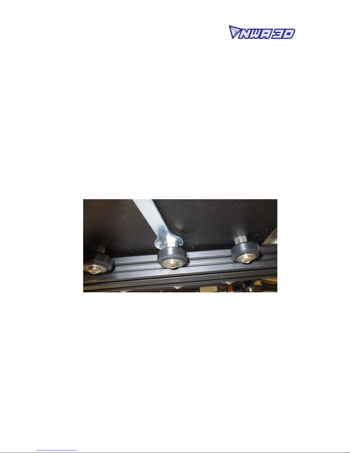
b. To tighten the gantry, rotate the one eccentric nut that connects the
wheel to the inside of the gantry. Use the open-end wrench to rotate the
nut slightly—a quarter turn is usually enough—until the wheel is snug
against the frame pillar and the gantry no longer wobbles.
10
© 2017 NWA3D LLC

NWA3D A31 User Manual
3. Adjust the tension of the nozzle assembly on the X-axis on the gantry frame.
a. Check the tension of the nozzle assembly. Hold the mounting bracket
behind the nozzle and try to wiggle it back and forth. If the nozzle
assembly wobbles on the X-axis frame, it is too loose.
b. To tighten the nozzle assembly, rotate the one eccentric nut that connects
the wheel to the bottom of the nozzle assembly. Use the open-end wrench
to rotate the nut slightly—a quarter turn is usually enough—until the
wheel is tight against the X-axis frame and the assembly no longer
wobbles.
c. Re-check the tension of the nozzle assembly. The assembly and the belt
should move left and right without much effort, but there should have no
side-to-side wiggle or play.
11
© 2017 NWA3D LLC

NWA3D A31 User Manual
4. Check the tension of the belt driving the Y-axis (under the build plate). The
belt should be taut, with no slack or slop. If the belt is loose:
a. Loosen the four bolts at the front of the base frame holding the belt
follower pulley to the base frame.
b. Using an Allen wrench as a lever, push the follower pulley to tighten the
belt.
c. Holding the belt taut, tighten the four bolts.
5. Check the tension of the belt driving the X-axis (on the gantry). The belt
should be taut, with no slack or slop. If the belt is loose:
a. Loosen the two bolts at the right side of the gantry holding the belt
follower pulley to the gantry.
b. Using an Allen wrench as a lever, push the follower pulley to tighten the
belt.
c. Holding the belt taut, tighten the two bolts.
12
© 2017 NWA3D LLC

NWA3D A31 User Manual
13
© 2017 NWA3D LLC

NWA3D A31 User Manual
4. Leveling the Build Plate
To build good parts, the build plate needs to be level, and the nozzle needs to be
about 0.1–0.2mm from the build plate in all locations. If you have a LokBuild
print surface, we recommend a distance of 0.20–0.25mm. This is about the
thickness of two pieces of paper (or one piece folded in half to double its
thickness). If you use painter’s tape as your print surface, we recommend a
distance of 0.1mm. This is about the thickness of a single piece of paper. You
want to adjust the height of the build plate so that you can barely slide the paper
between the nozzle and the build plate with only a little resistance.
1. Select Setup > Preheat PLA. This will heat the nozzle and melt any hardened
plastic that might be on the nozzle and affect the leveling process. This will
also heat the build plate and make the leveling more accurate.
2. When the nozzle and build plate reach the set temperatures, select Setup >
Auto home. This will move the nozzle to the home position at the front left
corner of the build plate.
3. Select Setup > Disable motors. This will allow you to move the nozzle
assembly (X axis) and build plate (Y axis) by hand.
Pro Tip: The Z axis stepper is also disabled, and you don’t want it
to move at all. So you should handle the printer gently during the
leveling process. Keep it flat and move the nozzle assembly
carefully.
4. Slide the paper between the nozzle and the build plate. Use a single sheet of
paper if you have painter’s tape on your build surface. Use two sheets (or one
folded in half) if you have a LokBuild print surface.
5. Adjust the four thumbscrews under the bed until the paper slides, with a tiny
bit of drag, in all locations on the build plate.
14
© 2017 NWA3D LLC

NWA3D A31 User Manual
6. Select Setup > Auto home, then Setup > Disable motors, and recheck in
several places. This is to make sure the Z-axis leadscrew didn’t rotate during
the leveling process.
7. You may need to make fine adjustments to the bed level when you start
printing. The first layer of the print will show whether the distance between
the nozzle and build plate is correct. Refer to the following graphic.
15
© 2017 NWA3D LLC

NWA3D A31 User Manual
a. If the bed is too low, the extruded plastic may not stick to the build plate.
Parallel lines of filament on the first layer will look rough, with high
tracks and low valleys.
b. If the bed is too high, the extruded plastic will squeeze out the sides of the
nozzle. The nozzle will plow the plastic and leave a first layer that is too
thin.
c. You can try to carefully adjust the thumbscrews during the first layer of
the build while the plate is moving until the distance between the build
plate and the nozzle is producing smooth extruded lines. Be careful of the
moving parts to not get pinched.
d. After you have fine-tuned the bed level during the first layer, you may
want to stop the build, clear the build plate, and restart the build.
16
© 2017 NWA3D LLC

NWA3D A31 User Manual
17
© 2017 NWA3D LLC

NWA3D A31 User Manual
5. Loading and Removing Filament
1. Loading filament
a. Load a spool of filament into the spool holder.
b. Cut off the used or bent end of the filament at an angle and it will be
easier to feed into the extruder and Bowden tube.
c. Feed the end of the filament into the extruder with one hand as you
squeeze the extruder release lever with your other hand.
d. Push the filament all the way through the white Bowden tube until it
stops when it hits the nozzle assembly.
e. Select Setup > Preheat PLA.
f. When the nozzle reaches the set temperature, check to make sure the
filament is fully loaded. This will also remove all of the material left in the
printer from the previous print. To do this, manually push filament
through the heated nozzle until the new color begins coming out of the
nozzle.
18
© 2017 NWA3D LLC

NWA3D A31 User Manual
Pro Tip: Never leave the printer preheated with material
inside of it for long periods of time. This will cause the
filament to bake inside of the nozzle assembly and can
cause it to clog.
2. Removing filament
To remove the filament cleanly, you should do a “soft pull.” This involves
heating the nozzle to 100°C, and then pulling the filament out of the printer.
a. Select Setup > Preheat soft pull and wait until the nozzle to reach the set
temperature.
b. When the nozzle temperature is 100°C, squeeze the extruder release
lever with one hand and pull the filament out of the extruder with your
other hand with one steady motion.
c. Cut the end of the filament to remove the partly melted plastic.
Pro Tip: Feed the end of the filament roll into the hole
on the side of the spool. This will insure it doesn’t get
tangled and cause a build to fail the next time you use it.
d. Remove the filament from the filament spool holder.
19
© 2017 NWA3D LLC

NWA3D A31 User Manual
6. Operation: The Four Steps of 3D Printing
3D printing involves four steps:
1. Create or find a 3D file
2. Slice the file for 3D printing
3. Send the file to the printer
4. Print!
1. Create or find a 3D file
a. You can create a 3D model—a digital geometry—using any CAD
(computer-aided design) software program. We recommend free
programs, such as TinkerCAD, OnShape, and Blender. Another is
SketchUp, which has free licenses available for schools. These programs
take some time to learn, and can be challenging. But they are also
rewarding, especially when you see your own creation being printed on
your 3D printer!
Every CAD program allows users to save or export digital files for 3D
printing. You want to save your file as an STL file (“filename.stl”). The STL
file is the standard file format for 3D printing. In some programs, it’s as
easy as the Save command. In others, you need to select the File > Export
option, and choose the STL format. OBJ files can also be sliced and 3D
printed.
b. You can find 3D models in many online libraries of digital content.
Thingiverse.com, GrabCAD, and Instructables are examples, and many
other sites exist.
2. Slice the file for 3D printing
Slicing is the process of converting your 3D model into the layered print
language your printer can understand, called G-Code. We recommend using
free, open-source slicer programs. Our favorite slicers are Cura and Repetier
Host. Both are free and easy to use. We’ve included Cura and its setup .ini file
on your printer’s SD card because it’s easier for beginners. We recommend
that you install Cura on a PC or Mac and use it to do your slicing.
There are a lot of slicers that will create G-Code automatically for your
printer. All you have to do is input the correct settings for your printer (using
the files we included), import your 3D model, and click slice! It’s that easy.
a. Install the Cura program on a PC or Mac.
b. Open the Cura application. You’ll then be given several options. In the Add
20
© 2017 NWA3D LLC
Other manuals for Afinibot A31
3
Table of contents
Other NWA3D 3D Printer manuals