3DBIZZ 3Dfeedy User manual

3DBIZZ UG (haftungsbeschränkt)
Zur Au 8 | 85256 Vierkirchen | Germany
info@3dbizz.com | www.3dbizz.com
3DFEEDY
INSTRUCTION MANUAL
Version 1.0
April 29, 2021

General Information » Read and keep the operation instructions
Version 1.0 2 von 25
TABLE OF CONTENTS
GENERAL INFORMATION ............................................................................................................................ 4
1. Read and keep the operation instructions ........................................................................................... 4
2. Legend of Symbols ................................................................................................................................. 4
SECURITY ...................................................................................................................................................... 5
1. Intended Use ............................................................................................................................................ 5
PREPARATION 3D-PRINTER ....................................................................................................................... 6
1. Disconnect Power Supply ...................................................................................................................... 6
2. Unplug PTFE Tube ................................................................................................................................. 6
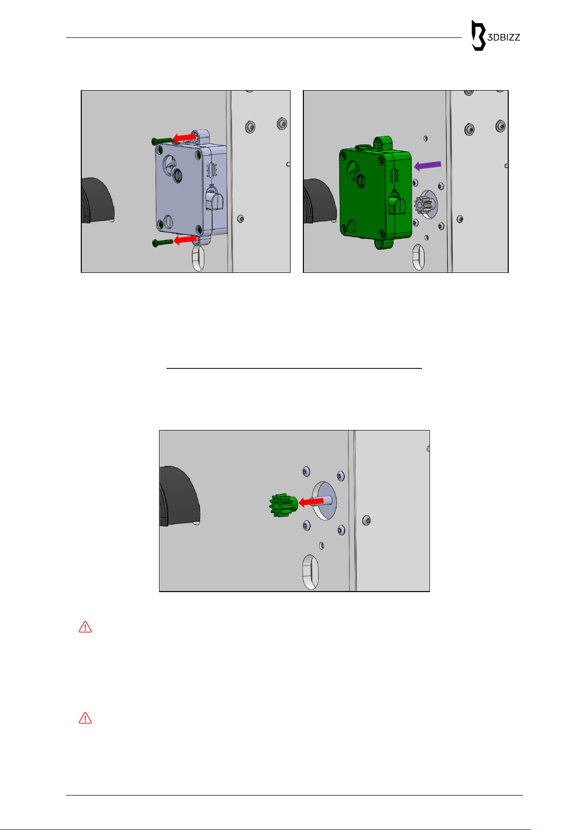
3. Remove Extruder .................................................................................................................................... 7
4. Remove Drive Gear ................................................................................................................................ 7
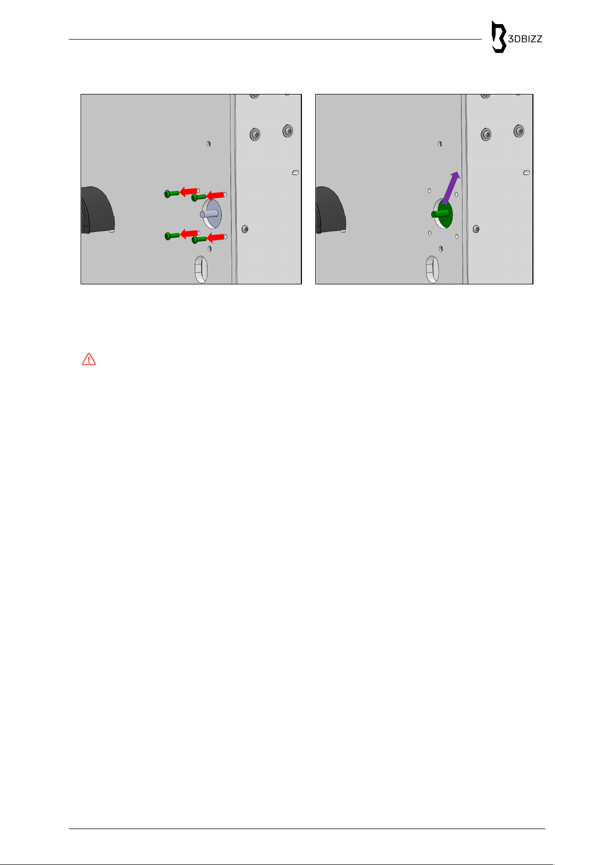
5. Remove Extruder Drive Motor ............................................................................................................... 8
PREPARATION 3DFEEDY ............................................................................................................................ 9
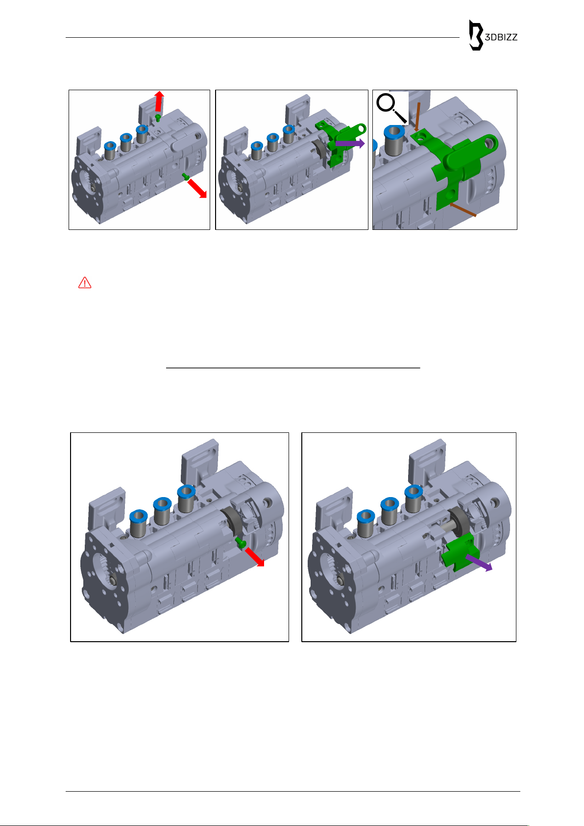
1. Remove Manual Adjustment Fixture .................................................................................................... 9
2. Remove First Selector Cover .............................................................................................................. 10
3. Remove Second Selector Cover ......................................................................................................... 10
4. Remove Third Selector Cover ............................................................................................................. 11
5. Remove Fourth Selector Cover ........................................................................................................... 11
6. Remove Selector Shaft ......................................................................................................................... 12
7. Remove Drive Gear Cover ................................................................................................................... 12
ASSEMBLY 3DFEEDY ................................................................................................................................ 14
1. Connect Drive Gear to Extruder Drive Motor .................................................................................... 14
2. Connect Extruder Drive Motor to Cover of Drive Unit ...................................................................... 15
2.1. Connect other Extruder Drive Motor sizes to Drive Unit Cover .................................................. 15
3. Marriage: Connect Extruder Drive Motor to 3Dfeedy ....................................................................... 16
3.1. Marriage: Connect other Extruder Drive Motor sizes to 3Dfeedy ............................................... 16
4. Insert Selector Shaft ............................................................................................................................. 17
5. Insert Fourth Selector Cover ................................................................................................................ 18
6. Insert Third Selector Cover .................................................................................................................. 18
7. Insert Second Selector Cover .............................................................................................................. 19
8. Insert First Selector Cover ................................................................................................................... 19
9. Insert Manual Adjustment Fixture ....................................................................................................... 20

General Information » Read and keep the operation instructions
Version 1.0 3 von 25
ASSEMBLY 3D-PRINTER ........................................................................................................................... 21
1. Install 3Dfeedy to 3D-Printer ................................................................................................................ 21
2. Insert PTFE Tubes to 3Dfeedy ............................................................................................................ 21
3. Insert PTFE Tubes to Collector ........................................................................................................... 22
4. Insert PTFE Tube to Collector ............................................................................................................. 22
5. Calibration of the Extruder ................................................................................................................... 23
6. Insert PTFE Tube to Printhead ............................................................................................................ 23
SERVICE AND MAINTENANCE ................................................................................................................. 24
1. Typical Problems ................................................................................................................................... 24
2. Cleaning and Maintenance .................................................................................................................. 25
3. Waste Management .............................................................................................................................. 25
4. Further Information ................................................................................................................................ 25

General Information » Read and keep the operation instructions
Version 1.0 4 von 25
GENERAL INFORMATION
1. Read and keep the operation instructions
These operating instructions belong to the multi-filament feeder of 3DBIZZ “3Dfeedy”. For the sake of
clarity, the multi-filament feeder will be referred to as "3Dfeedy" in the following. Read the operating
instructions carefully, especially the safety instructions, before using 3Dfeedy. Failure to follow these
operating instructions may result in injury or damage to 3Dfeedy or 3D-printers connected to. Applicable
local and national legislation regarding the use of this product must be followed. Keep the operating
instructions for further use. If you pass 3Dfeedy on to third parties, be sure to include this operating
manual.
For different languages and the most recent version of this document please visit:
www.3dbizz.com/manuals
2. Legend of Symbols
The following symbols and signal words are used in this instruction manual:
Electricity hazard
Keep out of the reach of children.
CHOKING HAZARD – Small parts not for children under 3 years or any individuals who
have a tendency to place inedible objects in their mouths.
Warnings require your attention. Failure to follow the instructions for proper set up, use and care
for your device can increase the risk of serious personal injury, death or property damage.
i The symbol indicates additional information for assembling and further tips.
• Colors in the image description correspond to the illustration for better comprehensibility.
• Parts in the illustration relevant for the work step are colored green.

Security » Intended Use
Version 1.0 5 von 25
SECURITY
1. Intended Use
3Dfeedy is designed exclusively for the home user in the hobby and do-it-yourself sector for the
following purposes:
• multi-filament printing
• number of filaments dependent on number of Feedy units; 3Dfeedy intended for 3 filaments.
• compatible filament is dependent on your 3D-printer.
All other applications are expressly excluded and are considered to be non-intended use. The
manufacturer or dealer accepts no liability for injuries, loss or damage caused by non-intended or
incorrect use.
Possible examples of non-intended or incorrect use are:
• use of the 3Dfeedy for purposes other than those for which it is intended;
• failure to observe the safety instructions and warnings, as well as the assembly, operating,
maintenance and cleaning instructions contained in this operating manual;
• failure to observe any accident prevention, occupational health or safety regulations specific
and/ or generally applicable to the use of 3D-printing equipment;
• use of accessories and spare parts not intended for the 3Dfeedy;
• modifications to the 3Dfeedy;
• repair of the 3Dfeedy by someone other than the manufacturer or a specialist;
• commercial, craft or industrial use of 3Dfeedy;
• operation or maintenance of 3Dfeedy by persons who are not familiar with the handling of the
feeder and/or do not understand the associated hazards.
Despite intended use, non-obvious residual risks cannot be completely ruled out.

Preparation 3D-Printer » Disconnect Power Supply
Version 1.0 6 von 25
PREPARATION 3D-PRINTER
The following steps are explained in general, as they are applicable the same way to any 3D-printer.
However, the pictures are shown as an example based on Ultimaker 2+, which makes the individual
steps probably look slightly different.
We cannot give any warranty for your 3D-printer. However, if you follow all the steps carefully
and take care of yourself and your printer, no damage is expected.
As you are installing 3Dfeedy to your 3D-printer, you have to make sure your 3D-printer does
have a CE-Conformity.
1. Disconnect Power Supply
Disconnect your 3D-printer from the power supply.
Failure to follow the instructions for proper set up, use and care for your device can increase the
risk of serious personal injury, death or property damage.
2. Unplug PTFE Tube
• Unplug the PTFE tube from the extruder.
• Unplug the PTFE tube from the printhead.
For unplugging the PTFE tube, usually a release button has to be used.

Preparation 3D-Printer » Remove Extruder
Version 1.0 7 von 25
3. Remove Extruder
• Unscrew the screws of the extruder.
• Remove the extruder.
i It could look different with your 3D-printer to the visualization shown above.
4. Remove Drive Gear
• Remove the drive gear from the extruder drive motor.
In some cases, an additional stud screw has to be removed or loosened.
i It could look different with your 3D-printer to the visualization shown above.
i Sometimes, the drive gear already fits to the drive gear of 3Dfeedy (e.g. Ultimaker 2+), which
makes it unnecessary to change it. You can check this by comparing the additional drive gear
from the box with the mounted one of your 3D-printer.
If the drive gear is tight fit to the extruder drive motor, do not damage the extruder drive motor.
Please purchase a new extruder drive motor with equal settings of the existing extruder drive
motor.

Preparation 3D-Printer » Remove Extruder Drive Motor
Version 1.0 8 von 25
5. Remove Extruder Drive Motor
• Unscrew the screws of the extruder drive motor.
• Remove the extruder drive motor.
i It could look different with your 3D-printer to the visualization shown above.
Make sure the 3D-printer is disconnected from the power supply.
i If it is necessary for dismounting the extruder drive motor, unplug the extruder drive motor cable
temporarily from the mainboard of your 3D-printer. Remember the plug position on your
mainboard.

Preparation 3Dfeedy » Remove Manual Adjustment Fixture
Version 1.0 9 von 25
PREPARATION 3DFEEDY
Before Installing 3Dfeedy to your 3D-printer, you have to prepare it for installing some components of
your 3D-printer, as 3Dfeedy is shipped in fully assembled state for quality check.
This is the initial configuration of 3Dfeedy in the box.
1. Remove Manual Adjustment Fixture
• Remove the manual adjustment fixture by unscrewing it by hand.

Preparation 3Dfeedy » Remove First Selector Cover
Version 1.0 10 von 25
2. Remove First Selector Cover
• Unscrew and remove the two screws with the Allen key.
• Now remove the transmission unit selector cover.
Be careful when removing the transmission unit selector cover for not breaking it!
• If the transmission unit selector cover is tight fit, carefully insert a thin screwdriver to the marked
edges to take it out of the grooves.
3. Remove Second Selector Cover
• Unscrew and remove the screw with the Allen key.
• Now remove the first repeater unit selector cover.

Preparation 3Dfeedy » Remove Third Selector Cover
Version 1.0 11 von 25
4. Remove Third Selector Cover
• Unscrew and remove the screw with the Allen key.
• Now remove the second repeater unit selector cover.
5. Remove Fourth Selector Cover
• Unscrew and remove the three screws with the Allen key.
• Now remove the drive unit selector cover.
Be careful when removing the drive unit selector cover for not breaking it!
• If the drive unit selector cover is tight fit, carefully insert a thin screwdriver to the marked edges
to take it out of the grooves.

Preparation 3Dfeedy » Remove Selector Shaft
Version 1.0 12 von 25
6. Remove Selector Shaft
• Remove the selector shaft from 3Dfeedy.
Be careful when removing the selector shaft for not damaging the housing at the transmission
unit!
• If the selector shaft is getting stuck at the housing of the transmission unit, carefully rotate the
shaft slightly to release the gear from the housing.
7. Remove Drive Gear Cover
• Unscrew and remove the two screws with the Allen key.
• Now remove the drive unit cover.

Preparation 3Dfeedy » Remove Drive Gear Cover
Version 1.0 13 von 25
The prepared 3Dfeedy for installing the necessary components of your 3D-printer looks like following:

Assembly 3Dfeedy » Connect Drive Gear to Extruder Drive Motor
Version 1.0 14 von 25
ASSEMBLY 3DFEEDY
Now 3Dfeedy is ready for marriage:
1. Connect Drive Gear to Extruder Drive Motor
i You may use the extruder drive motor from your 3D-printer uninstalled in chapter “Preparation
3D-Printer”.
i Alternatively, a new extruder drive motor can be bought and used for further steps.
If a new extruder drive motor was bought, make sure it has equal settings to your extruder drive
motor for not damaging the mainboard of your 3D-printer.
• Connect the drive gear from the box to the extruder drive motor by pushing it on the shaft if
necessary.
i Take a close look at the flat shaft of the extruder motor drive to correctly align and connect the
drive gear.

Assembly 3Dfeedy » Connect Extruder Drive Motor to Cover of Drive Unit
Version 1.0 15 von 25
2. Connect Extruder Drive Motor to Cover of Drive Unit
• Put the drive unit cover on the extruder drive motor.
i If the extruder drive motor is of the size NEMA 14 or NEMA 11 go to step 2.1 and take a closer
look on how to install these extruder drive motors.
i If the extruder drive motor is of a different size than NEMA 11, NEMA 14, NEMA 17, probably a
new drive unit cover has to be prepared in advance.
i If the motor shaft is too long use spacer between extruder drive motor and drive unit cover. This
will be shown in detail in the instruction “3Dfeedy Spacer Instruction Manual”.
• For NEMA 17 insert and tighten three M3x6 screws hand-tight with the Allen key to fix the
extruder drive motor to the drive unit cover.
2.1. Connect other Extruder Drive Motor sizes to Drive Unit Cover
• If the extruder drive motor is of the size NEMA 14, use the holes highlighted in red and fix the
extruder drive motor with four M3x6 screws from the box hand-tight with the Allen key.
• If the extruder drive motor is of the size NEMA 11, use the holes highlighted in purple and fix the
extruder drive motor with four M2.5x6 screws from the box hand-tight.
i If the motor shaft is too long use spacer between extruder drive motor and drive unit cover. This
will be shown in detail in the instruction “3Dfeedy Spacer Instruction Manual”.

Assembly 3Dfeedy » Marriage: Connect Extruder Drive Motor to 3Dfeedy
Version 1.0 16 von 25
3. Marriage: Connect Extruder Drive Motor to 3Dfeedy
• Connect the extruder drive motor with the drive unit cover to 3Dfeedy.
• Insert and tighten two M3x6 screws hand-tight with the Allen key.
• Insert and tighten the M3x12 screw from the box hand-tight with the Allen key.
i If the extruder drive motor is of the size NEMA 14 or NEMA 11, follow the steps 3.1.
3.1. Marriage: Connect other Extruder Drive Motor sizes to 3Dfeedy
…
• Connect the extruder drive motor with the drive unit cover to 3Dfeedy.
• Insert and tighten the two M3x6 screws hand-tight with the Allen key to fix the extruder drive
motor to 3Dfeedy.
• Insert a M3 hexagon nut from the box to the groove.
i If the steps of the manual “3DFeedy Spacer Instruction Manual” has been followed, sometimes
the hexagon nut is already installed.
• Insert and tighten the M3x6 screw from the box hand-tight with the Allen key.

Assembly 3Dfeedy » Insert Selector Shaft
Version 1.0 17 von 25
4. Insert Selector Shaft
• Insert the selector shaft to 3Dfeedy.
Be careful when inserting the selector shaft for not damaging the housing at the transmission
unit!
• After inserting the selector shaft carefully rotate it slightly to fit the highlighted area of the
selector shaft to the drive gear.
• If there are collisions when inserting the selector shaft, the components on the shaft may be
slipped and have to be repositioned during insertion.
• Try to rotate the manual adjustment wheel until the selector shaft starts to rotate.
i Slightly press in the selector shaft at the bearings to avoid it from pushing out.
i If the selector shaft starts to rotate, the selector shaft is correctly oriented.
i If the selector shaft does not start to rotate and the selector shaft is pressed out even though it
is fixed with your hands, the selector shaft is probably wrong oriented and the step marked in
violet should be repeated. This can usually also be seen when the bearing does not fit at all in
the groove.

Assembly 3Dfeedy » Insert Fourth Selector Cover
Version 1.0 18 von 25
5. Insert Fourth Selector Cover
• Insert the drive unit selector cover.
• Insert and tighten three M3x6 screws hand-tight with the Allen key.
6. Insert Third Selector Cover
• Insert the second repeater unit selector cover.
• Insert and tighten the M3x6 screw hand-tight with the Allen key.

Assembly 3Dfeedy » Insert Second Selector Cover
Version 1.0 19 von 25
7. Insert Second Selector Cover
• Insert the first repeater unit selector cover.
• Insert and tighten the M3x6 screw hand-tight with the Allen key.
8. Insert First Selector Cover
• Insert the transmission unit selector cover.
• Insert and tighten two M3x6 screws hand-tight with the Allen key.

Assembly 3Dfeedy » Insert Manual Adjustment Fixture
Version 1.0 20 von 25
9. Insert Manual Adjustment Fixture
• Insert and tighten the manual adjustment fixture hand-tight.
The assembled 3Dfeedy ready to install looks like following:
Table of contents