IFM Electronic Efector 400 User manual

Operating instructions
BasicLine encoders
Rx3xxx
706392/01 10/2015
UK

2
Contents
1 Preliminary note���������������������������������������������������������������������������������������������������3
1�1 Notes on this document���������������������������������������������������������������������������������3
1�2 Symbols used ������������������������������������������������������������������������������������������������3
2 Safety instructions �����������������������������������������������������������������������������������������������3
2�1 General����������������������������������������������������������������������������������������������������������3
2�2 Installation and connection ����������������������������������������������������������������������������3
3 Functions and features ����������������������������������������������������������������������������������������4
4 Installation������������������������������������������������������������������������������������������������������������4
4�1 Mounting drawings ����������������������������������������������������������������������������������������5
4�1�1 Type with synchro flange ����������������������������������������������������������������������5
4�1�2 Type with clamp flange and synchro flange������������������������������������������5
4�1�3 Type with hollow shaft ��������������������������������������������������������������������������6
5 Electrical connection��������������������������������������������������������������������������������������������6
6 Function���������������������������������������������������������������������������������������������������������������7
6�1 Output function / programming ����������������������������������������������������������������������7
7 IO-Link �����������������������������������������������������������������������������������������������������������������7
8 Technical data������������������������������������������������������������������������������������������������������8
8�1 Data sheets ���������������������������������������������������������������������������������������������������8
8�2 Accessories����������������������������������������������������������������������������������������������������8
9 Maintenance, repair and disposal������������������������������������������������������������������������8
10 Approvals/standards ������������������������������������������������������������������������������������������8

3
UK
1 Preliminary note
1.1 Notes on this document
This document applies to encoders of the following types:
• BasicLine encoders with magnetic detection system, order numbers Rx3xxx
It is part of the device and contains information about the correct handling of the
product�
This document is intended for qualified electricians� These specialists are people
who are qualified by their training and their experience to recognise and to avoid
possible hazards that may be caused during operation of the device�
►Read this document before using the device�
►Keep this document during the service life of the device�
1.2 Symbols used
►Instructions
> Reaction, result
[…] Designation of keys, buttons or indications
→Cross-reference
Important note
Non-compliance may result in malfunction or interference�
Information
Supplementary note
2 Safety instructions
2.1 General
►Observe these operating instructions�
►Adhere to the warning notes on the product�
Non-observance of the instructions, operation which is not in accordance with use
as prescribed below, wrong installation or incorrect handling can affect the safety
of operators and machinery�
2.2 Installation and connection
The device must only be installed, connected and put into operation by a qualified
electrician as the safe function of the device and machinery is only guaranteed
when installation is correctly carried out�

4
The installation and connection must comply with the applicable national and
international standards� Responsibility lies with the person installing the device�
Note: This product complies with the standard EN61000-6-4� The unit may cause
radio interference in domestic areas� The user must take appropriate measures to
avoid this interference, if necessary�
3 Functions and features
The encoder converts rotary movements into digital numerical values� Each
angular position of the revolutions is provided as a numerical value�
These values allow angular movements to be measured and positions to be
determined�
Products from ifm electronic gmbh are usually individual components of larger
installations� These applications require tests of the entire installation and do not only
depend on the specification of these components� The notes in these instructions
apply only to the product from ifm electronic and not to the entire installation� If the
product is used in a non-intended way, this will be at your own risk�
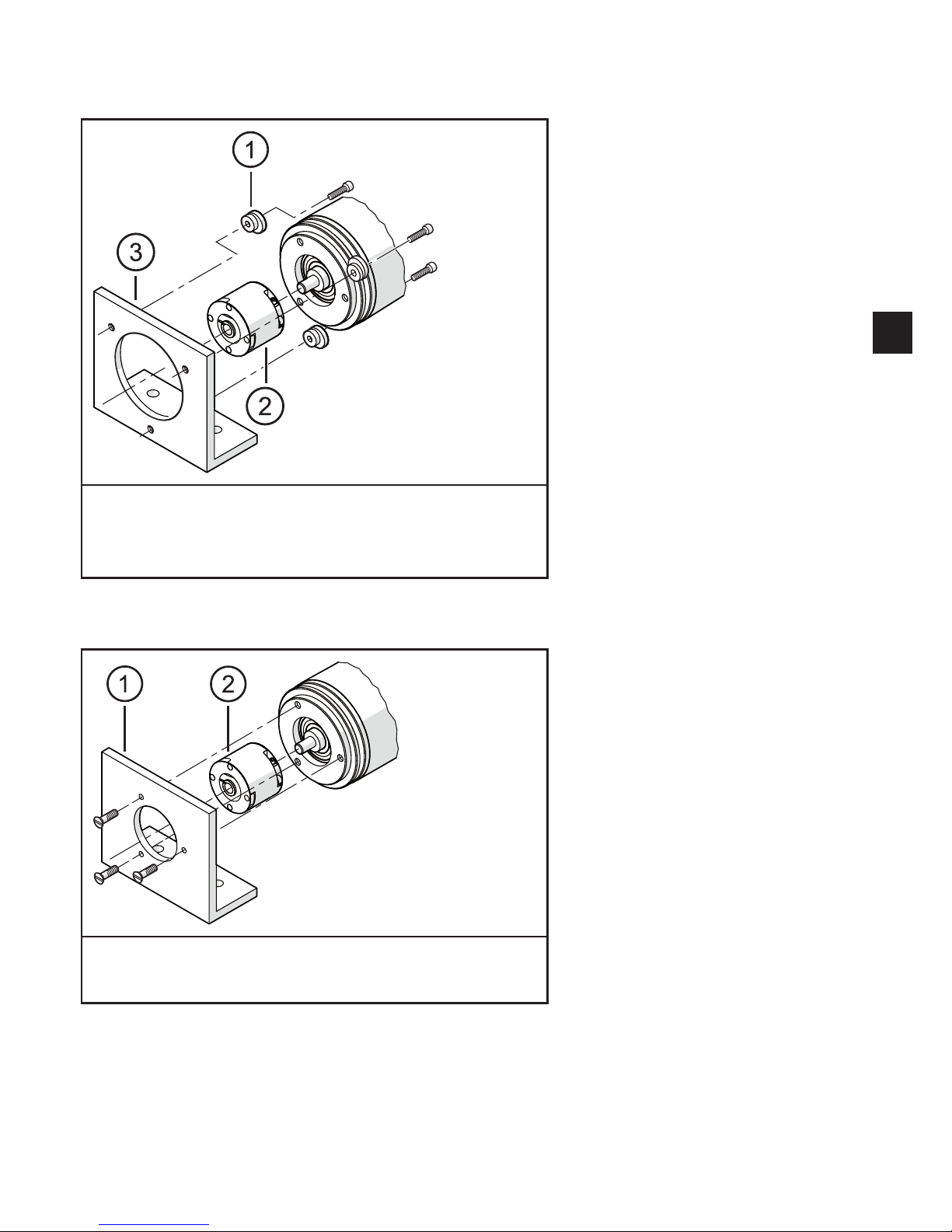
4 Installation
►Disconnect power�
►Ensure that the machine stands still�
►The drive must not be started during installation�
►Do not hit the shaft; do not use a file or similar tool on the shaft: risk of
destruction!
This product is a precision measuring device� Therefore it has to be handled with
care by trained staff� The following warnings apply to influences outside the limit
values indicated in the product data sheet�
Damage to the product can be caused by:
• too high forces on the shaft
• humidity and chemical liquids (do not connect any cables oriented upwards)
• extreme temperatures
• too high vibrations and shocks
• short circuit or too high an operating voltage
• impact, shock or any other physical forces

5
UK
4.1 Mounting drawings
4.1.1 Type with synchro flange
1: fastening clamp (3 pieces) E60041
2: clutch
3: angle bracket
4.1.2 Type with clamp flange and synchro flange
1: angle bracket
2: clutch
►Minimise the displacement between the two shafts�
►Avoid the following mistakes:
- radial displacement
- angular displacement

6
- axial movement
►To minimise the forces on the shaft use a flexible shaft coupling with guiding
slot for the installation�
4.1.3 Type with hollow shaft
Version with one stator coupling Version with two stator couplings
1: angle bracket
►Verify the radial displacement after installation and with slow rotation�
The displacement must not be larger than 0�5 mm since otherwise the life cycle of
the encoder may be shortened or the system accuracy impaired�
5 Electrical connection
►Disconnect power�
►Connect the device according to the indications on the type label�
►For the wiring please see the type label
►Keep potential interfering sources (magnets, heat sources) at a distance�
Ensure that the cable length does not exceed the value indicated in the data
sheet�

7
UK
For frequency converters on asynchronous motors use a screened cable for perfect
data transmission�
►Ensure grounding via the screen�
►Ensure that the bending radius (R) of the cable does not exceed the
permissible minimum value�
Bending radius of the firmly laid cable: 25 mm (5 x cable diameter)
Bending radius of the freely laid cable: 50 mm (10 x cable diameter)
6 Function
• The unit generates output signals according to the parameter settings�
• It moreover provides the process data via IO-Link�
• The unit is laid out for fully bidirectional communication� So, the following
options are possible:
IO-Link
- Remote display: reading and displaying the current settings�
- Remote parameter setting: reading and changing the current parameter
setting�
- IO-Link parameter setting
6.1 Output function / programming
• HTL 50 mA (preset by the factory) / 5 V TTL 20 mA
• Parameter setting options via IO-Link:
- Resolution per revolution 1���9999
- HTL, TTL level
- rotational direction
7 IO-Link
General information
This device has an IO-Link communication interface which requires an IO-Link-
capable module (IO-Link master) for operation�
The IO-Link interface enables direct access to the process and diagnostic
data and provides the possibility to set the parameters of the unit� In addition
communication is possible via a point-to-point connection with a USB adapter
cable�

8
You will find the IODDs necessary for the configuration of the IO-Link device and
detailed information about process data structure, diagnostic information, device-
specific information, parameter setting tools and parameter addresses at
www�ifm�com�
8 Technical data
8.1 Data sheets
Data sheets are available at:
www�ifm�com
8.2 Accessories
You will find matching accessories at:
www�ifm�com
9 Maintenance, repair and disposal
►Dispose of the device in accordance with the national environmental
regulations�
10 Approvals/standards
The EC declaration of conformity and approvals can be found at:
www�ifm�com

9
UK
Table of contents
Other IFM Electronic Media Converter manuals

IFM Electronic
IFM Electronic E7354A User manual

IFM Electronic
IFM Electronic Efector 400 RA Series User manual

IFM Electronic
IFM Electronic E70454 User manual

IFM Electronic
IFM Electronic Efector 400 RO Series User manual

IFM Electronic
IFM Electronic Efector 400 RM30 Series Application guide

IFM Electronic
IFM Electronic Efector 400 RV User manual

IFM Electronic
IFM Electronic Efector 400 RN30 Series Application guide

IFM Electronic
IFM Electronic AS-i CompactLineM12 User manual