Connection
examples *6
Performance_Level: e to
DIN EN ISO 13849-1
SIL 3 to DIN EN 61508
Category 4 to EN954-1
We reserve the right to make alterations without prior notice
ifm electronic.gmbh Date: 22.03.07
&RQWHQWV 3DJH
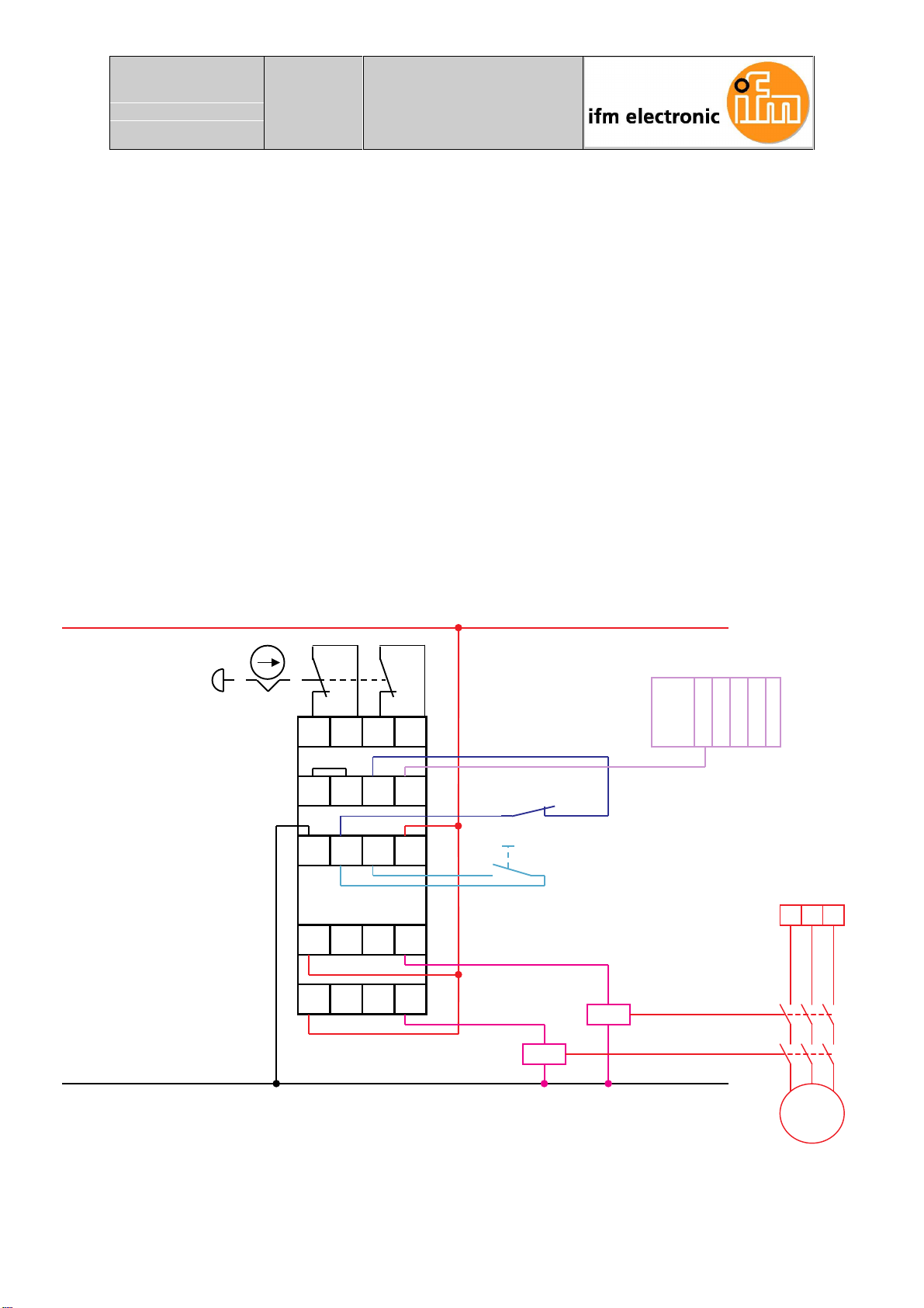
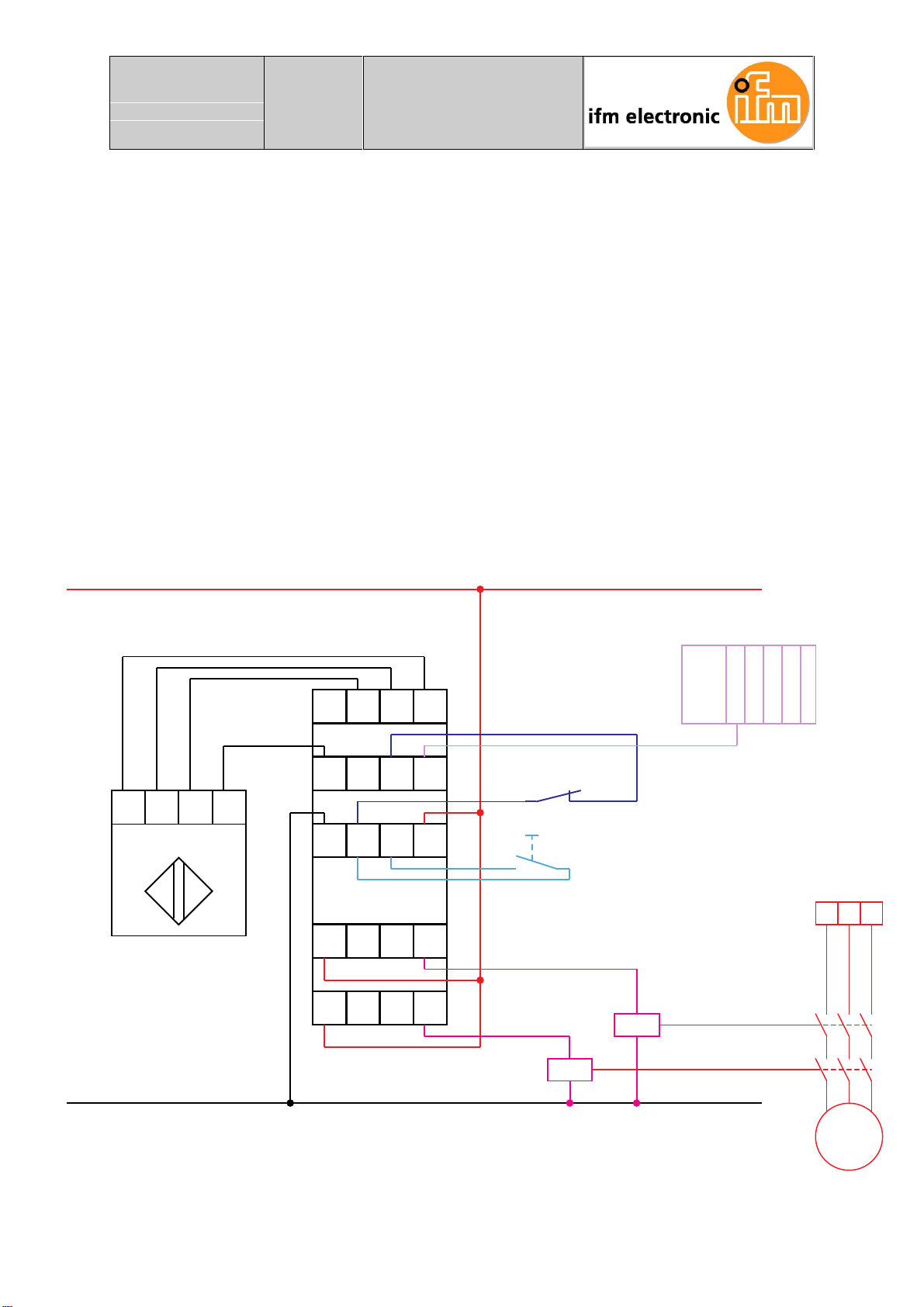
(6723$33/,&$7,21
7ZRFKDQQHOVZLWKPRQLWRUHGVWDUWDQGUHOD\FRQWUROZLWKIHHGEDFNORRSPRQLWRULQJ
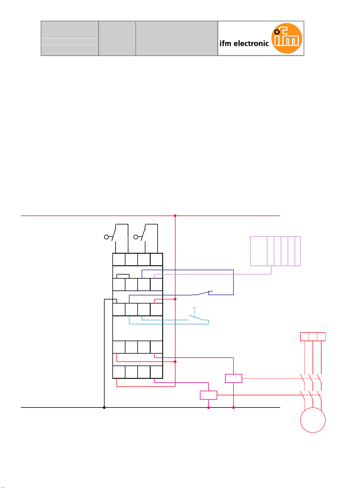
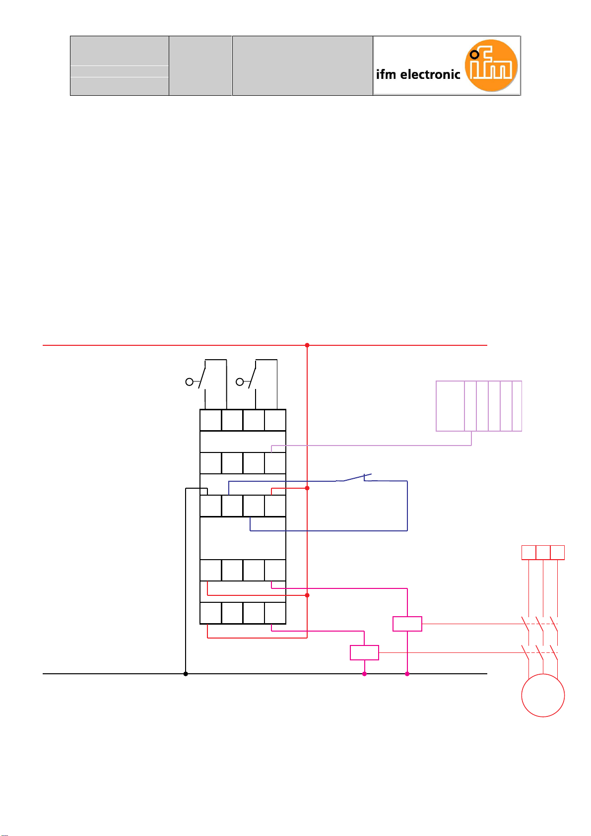
3527(&7,9(*8$5'$33/,&$7,21
:LWKPRQLWRUHGVWDUW
:LWKDXWRPDWLFVWDUW
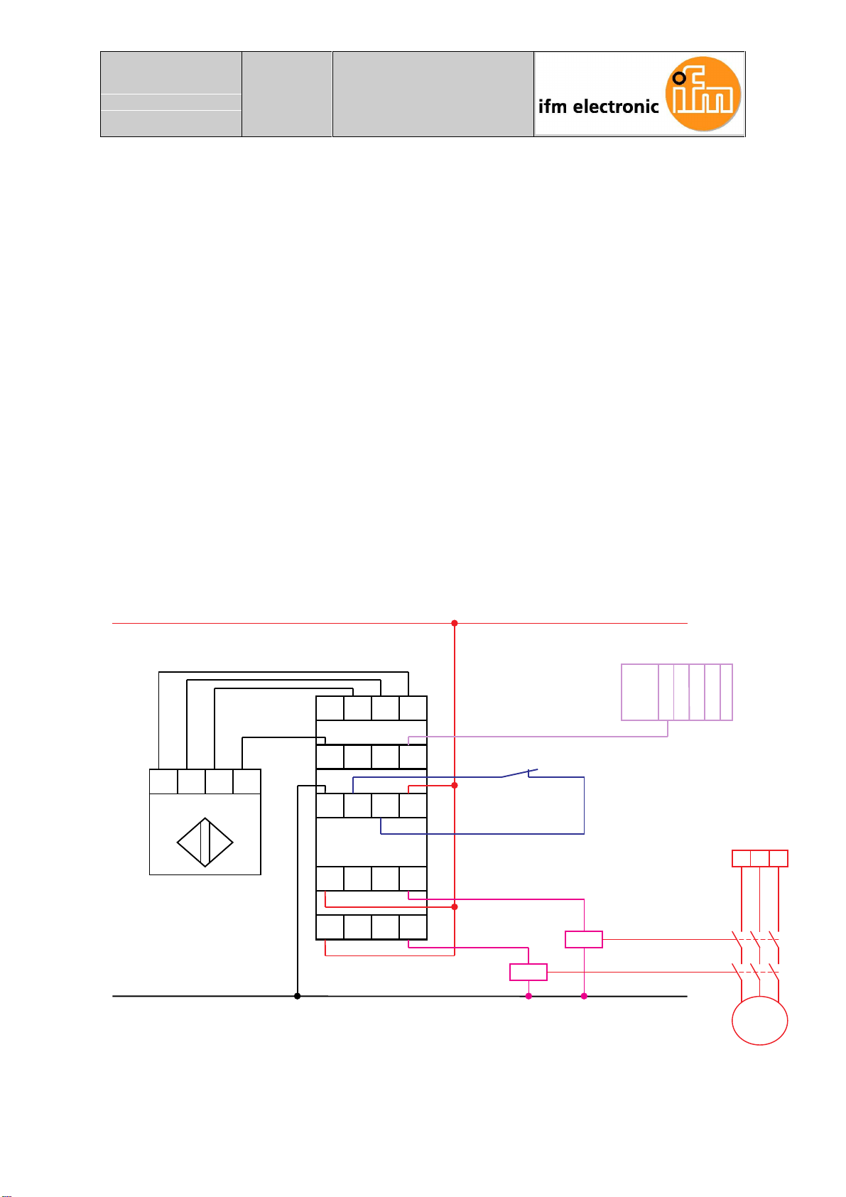
&211(&7,212)$121&217$&76$)(7<'(9,&(:,7+6(0,&21
'8&7252873876;36:,7&+,1*(**067+528*+%($0
6(1625/,*+7&857$,1/$6(56&$11(5
:LWKDXWRPDWLFVWDUWDQGVXSSO\RIWKHQRQFRQWDFWVDIHW\GHYLFHFXUUHQWFRQVXPSWLRQ
P$YLDWKH*6
:LWKPRQLWRUHGVWDUWDQGVXSSO\RIWKHQRQFRQWDFWVDIHW\GHYLFHFXUUHQWFRQVXPSWLRQ
P$YLDWKH*6
:LWKDXWRPDWLFVWDUWDQGH[WHUQDOVXSSO\RIWKHQRQFRQWDFWVDIHW\GHYLFHFXUUHQW
FRQVXPSWLRQ!P$
:LWKPRQLWRUHGVWDUWDQGH[WHUQDOVXSSO\RIWKHQRQFRQWDFWVDIHW\GHYLFHFXUUHQW
FRQVXPSWLRQ!P$
&211(&7,212)$&/2&.(')$,/6$)(6(1625(**06**6
*,6(7&
:LWKDXWRPDWLFVWDUWDQGVXSSO\RIWKHIDLOVDIHVHQVRUYLDWKH*6
:LWKPRQLWRUHGVWDUWDQGVXSSO\RIWKHIDLOVDIHVHQVRUYLDWKH*6
:LWKDXWRPDWLFVWDUWDQGH[WHUQDOVXSSO\RIWKHQRQFRQWDFWVDIHW\GHYLFH
:LWKPRQLWRUHGVWDUWDQGH[WHUQDOVXSSO\RIWKHQRQFRQWDFWVDIHW\GHYLFH
7:2+$1'&21752/86,1*0(&+$1,&$/6:,7&+(6
7:2+$1'&21752/86,1*(/(&7521,&6(16256