IFM DV2900 User manual

Operating instructions
20-LED light tower
DV2900
DV2910
DV2920
DV2930
11455266 / 0007 / 2022
GB

DV2900 DV2910 DV2920 DV2930 20-LED light tower
2
Contents
1 Preliminary note ............................................................. 3
1.1 Symbols used.......................................................... 3
2 Safety instructions............................................................ 4
3 Intended use................................................................ 5
4 Function ................................................................... 6
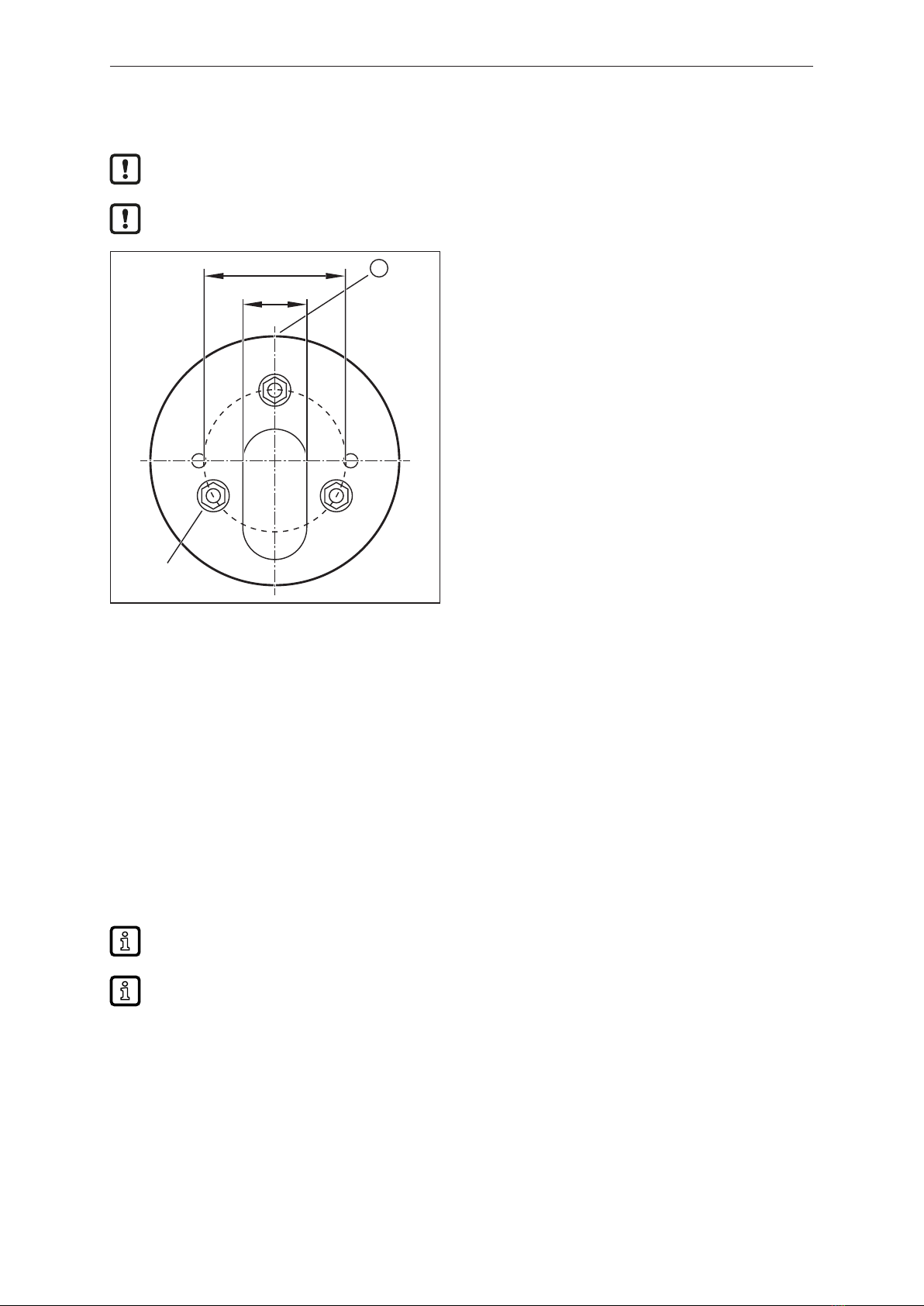
5 Installation.................................................................. 7
6 Electrical connection.......................................................... 8
6.1 Pin assignment......................................................... 8
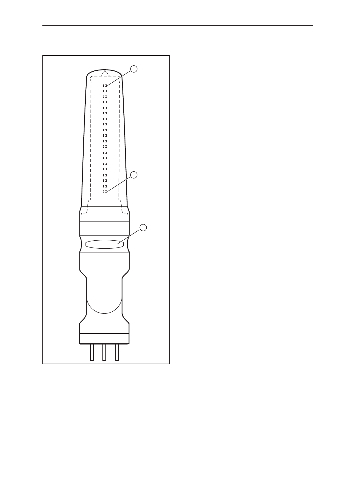
7 Operating and display elements................................................. 9
7.1 Signal Light Mode....................................................... 9
7.2 Level Meter Mode....................................................... 10
8 Operation .................................................................. 11
8.1 Signal Light Mode....................................................... 11
8.2 Level Meter Mode....................................................... 11
8.3 User-specific colour combinations........................................... 12
9 Parameter setting............................................................ 14
9.1 Identification........................................................... 14
9.1.1 Application-specific tag............................................... 14
9.1.2 Function tag ....................................................... 14
9.1.3 Location tag ....................................................... 14
9.2 Parameter............................................................. 14
9.2.1 Operating mode .................................................... 15
9.2.2 LED Intensity....................................................... 15
9.2.3 Buzzer Intensity .................................................... 15
9.2.4 User preference color Bank 1. LED x . . . . . . . . . . . . . . . . . . . . . . . . . . . . . . . . . . . . 15
9.2.5 User preference color Bank 2. LED x . . . . . . . . . . . . . . . . . . . . . . . . . . . . . . . . . . . . 15
9.2.6 User preference color Bank 3. LED x . . . . . . . . . . . . . . . . . . . . . . . . . . . . . . . . . . . . 15
9.2.7 Select user color.................................................... 15
9.2.8 Blank between Segments............................................. 15
9.2.9 Segment colors. Segment x ........................................... 16
9.2.10 Segment appearance. Segment x . . . . . . . . . . . . . . . . . . . . . . . . . . . . . . . . . . . . . . . 16
9.2.11 Size of segment. Segment x........................................... 16
9.2.12 Direction of flow .................................................... 16
9.2.13 Scope of appearance ................................................ 17
9.2.14 Level meter thresholds. LED x ......................................... 17
9.2.15 LED Colors. LED x .................................................. 18
9.2.16 LED appearance. LED x.............................................. 18
10 Maintenance, repair and disposal................................................ 19

20-LED light tower DV2900 DV2910 DV2920 DV2930
3
1 Preliminary note
You will find instructions, technical data, approvals and further information using the QR code on the
unit / packaging or at www.ifm.com.
1.1 Symbols used
Requirement
Instructions
Reaction, result
[...] Designation of keys, buttons or indications
Cross-reference
Important note
Non-compliance may result in malfunction or interference.
Information
Supplementary note

DV2900 DV2910 DV2920 DV2930 20-LED light tower
4
2 Safety instructions
• The unit described is a subcomponent for integration into a system.
– The system architect is responsible for the safety of the system.
– The system architect undertakes to perform a risk assessment and to create documentation in
accordance with legal and normative requirements to be provided to the operator and user of
the system. This documentation must contain all necessary information and safety instructions
for the operator, the user and, if applicable, for any service personnel authorised by the
architect of the system.
• Read this document before setting up the product and keep it during the entire service life.
• The product must be suitable for the corresponding applications and environmental conditions
without any restrictions.
• Only use the product for its intended purpose (Ò Intended use).
• If the operating instructions or the technical data are not adhered to, personal injury and/or damage
to property may occur.
• The manufacturer assumes no liability or warranty for any consequences caused by tampering with
the product or incorrect use by the operator.
• Installation, electrical connection, set-up, programming, configuration, operation and maintenance
of the product must be carried out by personnel qualified and authorised for the respective activity.
• Protect units and cables against damage.
• Replace damaged units, otherwise the technical data and safety will be impaired.
• Observe applicable documents.

20-LED light tower DV2900 DV2910 DV2920 DV2930
5
3 Intended use
The unit is used for the visual display of machine conditions. The versions DV2910 and DV2930
additionally have a buzzer for acoustic signalling.
The LEDs / LED segments and the audible warning device can be switched on and off individually.
The unit is not suited for environments with particular requirements on mechanical stability (e.g.
shock/vibration).
The unit is intended for indoor use only.
uObserve the operating conditions (Ò Technical data at www.ifm.com).
The unit is not approved for safety-related tasks in the field of operator protection.

DV2900 DV2910 DV2920 DV2930 20-LED light tower
6
4 Function
This unit has an IO-Link communication interface which enables direct access to process and
diagnostic data. In addition it is possible to set the parameters of the unit while it is in operation.
Operation of the unit via the IO-Link interface requires an IO-Link master.
With a PC, suitable IO-Link software and an IO-Link adapter cable, communication is possible while
the system is not in operation.
The IODDs necessary for the configuration of the unit, detailed information about process data
structure, diagnostic information, parameter addresses and the necessary information about the
required IO-Link hardware and software can be found at www.ifm.com.

20-LED light tower DV2900 DV2910 DV2920 DV2930
7
5 Installation
uDisconnect the power of the machine before installation.
uFor installation choose a flat mounting surface.
1
18
40
M4
Fig.1: Fixture (view from bottom)
1: Front side
uAttach the fixture for the device to the mounting surface using the supplied M4 nuts. Tightening
torque 1.8 Nm.
uOnly with the models DV2900 and DV2910:
For mounting on a horizontal surface attach the base to the fixture (overlapping marks on base and
fixture) and turn clockwise by approx. 10 ° to fix it. For mounting on a vertical surface loosen the
screw in the base, turn the upper part of the base by 180 ° and tighten the screw again. Attach the
base to the fixture (overlapping marks on base and fixture) and turn clockwise by approx. 10 ° to fix
it.
uInsert the cable through the fixture and, if necessary, the base and connect the socket with the M12
connector in the signal lamp. Tightening torque max. 0.4 Nm. (Observe the maximum tightening
torque of the connection cables.)
uAttach the signal lamp to the fixture or the base (overlapping marks) and turn clockwise by approx.
10 ° to fix it.
Integrated seals at the bottom of the fixture and in the base as well as O-rings at the fixture and
base prevent ingress of moisture.
Information about available accessories at www.ifm.com

DV2900 DV2910 DV2920 DV2930 20-LED light tower
8
6 Electrical connection
The unit must be connected by a qualified electrician.
Observe the national and international regulations for the installation of electrical equipment.
Voltage supply according to SELV, PELV.
The IO-Link port must be connected according to the IO-Link specification.
uDisconnect power.
uConnect the cable with the M12 connector of the unit.
Tightening torque max. 0.4 Nm.
Observe the maximum tightening torque of the connection cable.
6.1 Pin assignment
M12 plug IO-Link, 4-pole (4 x 0.34 mm² / AWG 22)
43
2 1
1: L+
2: not used
3: L-
4: IO-Link

20-LED light tower DV2900 DV2910 DV2920 DV2930
9
7 Operating and display elements
7.1 Signal Light Mode
2
3
4
5
6
1
1: Segment 1 with 4 RGB LEDs as factory setting (number and size of the LED segment can be configured)
2: Segment 2 with 4 RGB LEDs as factory setting (number and size of the LED segment can be configured)
3: Segment 3 with 4 RGB LEDs as factory setting (number and size of the LED segment can be configured)
4: Segment 4 with 4 RGB LEDs as factory setting (number and size of the LED segment can be configured)
5: Segment 5 with 4 RGB LEDs as factory setting (number and size of the LED segment can be configured)
6: Buzzer (only DV2910 and DV2930)

DV2900 DV2910 DV2920 DV2930 20-LED light tower
10
7.2 Level Meter Mode
2
3
1
1: LED 20 as factory setting (direction of movement of LED control can be configured)
2: LED 1 as factory setting (direction of movement of LED control can be configured)
3: Buzzer (only DV2910 and DV2930)

20-LED light tower DV2900 DV2910 DV2920 DV2930
11
8 Operation
Connect the unit to an IO-Link master (master port class A) using a 4-pole connection cable. The
controller switches the individual LEDs / LED segments on and off in the configured colours according
to the set parameters.
Via the parameter [Operating mode] the following modes can be set:
• Signal Light Mode
• Level Meter Mode
8.1 Signal Light Mode
While the device is operating, the controller switches the LED segments and the buzzer (if present) on
and off (PDout, cyclical data communication). Signalling corresponds to the pre-defined parameters
for the individual LED segments and the buzzer.
Via the acyclic parameter setting the following properties can be set for every LED segment:
• Segment size (number of LEDs for the individual LED segments)
A maximum of 20 LEDs can be divided into a maximum of 5 LED segments.
• Space between the segments
The lowest LED in each LED segment can be switched off.
• Colour per LED segment (off, red, green, orange, blue, violet, turquoise, white, user-specific)
• Colours of the 20 LEDs (3 user-specific combinations with a maximum of 20 colours each)
• Frequency per LED segment (permanently on, flashing slow/medium/fast, blinking slow/medium/
fast)
• Brightness of all LEDs (0...100 %)
For the models with an acoustic signal device the audibility of the buzzer can be set (0…100 %).
7 6 5 4 3 2 1 0 PDout
--- Buzzer sound (buzzer style 1...8) --- User-specific colour com-
bination (Bank 1, 2, 3 or
none)
Buzzer Byte 0
--- --- --- Segment 5 Segment 4 Segment 3 Segment 2 Segment 1 Byte 1
8.2 Level Meter Mode
While in operation the controller transmits an analogue value between 0 and 100 % in byte 1 via
PDout. The device indicates it if the analogue value exceeds configured thresholds. Byte 0 determines
the display of the visual signalling as well as the acoustic signal (only for DV2910 and DV2930).

DV2900 DV2910 DV2920 DV2930 20-LED light tower
12
Position Threshold value Colour Flashing frequency
LED 20
LED 19
LED 18
LED 17
LED 16
LED 15
LED 14
LED 13
LED 12
LED 11
LED 10
LED 9
LED 8
LED 7
LED 6
LED 5
LED 4
LED 3
LED 2
LED 1
95
90
85
80
75
70
65
60
55
50
45
40
35
30
25
20
15
10
5
0
1 (red)
1 (red)
1 (red)
1 (red)
5 (orange)
5 (orange)
5 (orange)
5 (orange)
9 (green)
9 (green)
9 (green)
9 (green)
11 (turquoise)
11 (turquoise)
11 (turquoise)
11 (turquoise)
13 (blue)
13 (blue)
13 (blue)
13 (blue)
Blinking fast
Blinking fast
Blinking fast
Blinking fast
Blinking medium
Blinking medium
Blinking medium
Blinking medium
Flashing fast
Flashing fast
Flashing fast
Flashing fast
Flashing medium
Flashing medium
Flashing medium
Flashing medium
Flashing slow
Flashing slow
Flashing slow
Flashing slow
Fig.2: Application example
Via acyclic parameter setting, the following properties can be set for the LEDs:
• Direction of movement (from bottom to top or from top to bottom)
• Level thresholds per LED (a maximum of 20 thresholds between 0 and 100 in ascending order)
When the threshold is exceeded, the corresponding LED is activated.
• Colours of the 20 individual LEDs (20 different colours each or off)
• Colours of the 20 LEDs (3 user-specific combinations with a maximum of 20 colours each)
• Frequency per LED (permanently on, flashing slow/medium/fast, blinking slow/medium/fast)
• Display range (all LEDs, individual LEDs, top LED only)
• Brightness (0...100 %)
For the models with an acoustic signal device the audibility of the buzzer can be set (0…100 %).
76543210PDout
--- Buzzer sound (buzzer style 1...8) --- User-specific colour com-
bination (Bank 1, 2, 3 or
none)
Buzzer Byte 0
--- Analogue value 0...100 % Byte 1
8.3 User-specific colour combinations
In both Signal Light Mode and Level Meter Mode, the LEDs are controlled according to the process
data.
Independently of this, the user has the option of defining three different colour combinations (User
preference color Bank 1, Bank 2 and Bank 3).

20-LED light tower DV2900 DV2910 DV2920 DV2930
13
If a number from 1-3 is sent in the process data (byte 0, bit 1+2), the current display of the segments /
LEDs is overwritten with the selected colour combination Bank 1, 2 or 3. For example, in Level Meter
Mode, a warning message can be switched to when a certain event occurs (e.g. all LEDs flash red).

DV2900 DV2910 DV2920 DV2930 20-LED light tower
14
9 Parameter setting
Parameters can be set before installation or during operation.
If you change parameters during operation, this will influence the function of the plant.
uEnsure that there will be no malfunctions in your plant.
During parameter setting the unit remains in the operating mode. It continues to monitor with the
existing parameter until the parameter setting has been completed.
Depending on the parameter setting, the parameters available in the menu may change.
Requirements for parameter setting via the IO-Link interface:
üA suitable parameter setting software, e.g. ifm moneo|configure
üThe Input Output Device Description (IODD) for the device, see documentation.ifm.com
üOne IO-Link master
uConnect the IO-Link master to a parameter setting software.
uSet the port of the master to the IO-Link operating mode.
uConnect the device to a free port of the IO-Link master.
wThe unit switches to IO-Link mode.
uChange parameter settings in the software.
uWrite parameter settings to the unit.
Notes on parameter setting Ò Manual of the parameter setting software
9.1 Identification
Under [Identification], individual identifiers can be assigned to the device via the following parameters:
9.1.1 Application-specific tag
Customer-specific application description, max. 32 characters long.
Default value: “ *** ” / can be freely defined by the customer
9.1.2 Function tag
Customer-specific function tag of the unit, max. 32 characters long.
Default value: “ *** ” / can be freely defined by the customer
9.1.3 Location tag
Customer-specific location tag of the unit, max. 32 characters long.
Default value: “ *** ” / can be freely defined by the customer
9.2 Parameter
The type of signalling is configured under [Parameters].

20-LED light tower DV2900 DV2910 DV2920 DV2930
15
9.2.1 Operating mode
Setting of the operating mode
• Signal Light Mode (Ò/11)
• Level Meter Mode (Ò/11)
Factory setting: Signal Light Mode
9.2.2 LED Intensity
Setting of the LED brightness
• 0…100
Factory setting: 70
9.2.3 Buzzer Intensity
Setting of the buzzer volume
• 0…100
Factory setting: 100
9.2.4 User preference color Bank 1. LED x
Colour definition of the 20 LEDs in user-specific combination 1
For each LED, 1 of 21 colours or the switched off state can be configured.
Factory setting for all LEDs: Off
9.2.5 User preference color Bank 2. LED x
Colour definition of the 20 LEDs in user-specific combination 2
For each LED, 1 of 21 colours or the switched off state can be configured.
Factory setting for all LEDs: Off
9.2.6 User preference color Bank 3. LED x
Colour definition of the 20 LEDs in user-specific combination 3
For each LED, 1 of 21 colours or the switched off state can be configured.
Factory setting for all LEDs: Off
9.2.7 Select user color
Setting of a user-specific colour
1 of 21 colours or the switched off state can be configured.
Factory setting: Lemon
This parameter is only available in Signal Light Mode.
9.2.8 Blank between Segments
Setting of spaces between the individual segments
The lowest LED in each LED segment can be switched off.

DV2900 DV2910 DV2920 DV2930 20-LED light tower
16
• Activated
• Deactivated (factory setting)
This parameter is only available in Signal Light Mode.
9.2.9 Segment colors. Segment x
Colour definition for all LEDs in this segment
• Off
• Red (factory setting for segment 1)
• Green (factory setting for segment 3)
• Orange (factory setting for segment 2)
• Blue (factory setting for segment 5)
• Violet
• Turquoise
• White (factory setting for segment 4)
• User-specific configuration: see parameters Select user color (Ò/15)
This parameter is only available in Signal Light Mode.
9.2.10 Segment appearance. Segment x
Setting of the flashing frequency for this segment
• Permanently on (factory setting for segment 1...5)
• Flashing slow
• Flashing medium
• Flashing fast
• Blinking slow
• Blinking medium
• Blinking fast
This parameter is only available in Signal Light Mode.
9.2.11 Size of segment. Segment x
Number of LEDs for this LED segment
A maximum of 20 LEDs can be divided into a maximum of 5 LED segments. If a total of 20 LEDs is
assigned, no further segment can be configured.
• 0…20
Factory setting for segment 1...5: 4
This parameter is only available in Signal Light Mode.
9.2.12 Direction of flow
Setting of the direction of movement for increasing input value with exceeded thresholds

20-LED light tower DV2900 DV2910 DV2920 DV2930
17
• From bottom to top (factory setting)
• From top to bottom
This parameter is only available in Level Meter Mode.
9.2.13 Scope of appearance
Setting of the colour and flashing frequency for the LEDs that are activated by exceeded thresholds
• All LEDs (factory setting)
The colour and flashing frequency of the LED with the currently highest exceeded threshold are
adopted for all LEDs with a lower threshold configuration.
• Individual LEDs
For each LED activated by an exceeded threshold, the colour and flashing frequency from the
associated parameters are kept.
• Only the top LED
The colour and flashing frequency of the LED with the currently highest exceeded threshold are
kept from the associated parameters.
For all LEDs with lower threshold configuration, the colour from the associated parameters is kept.
However, they light up permanently.
This parameter is only available in Level Meter Mode.
9.2.14 Level meter thresholds. LED x
Setting of the level threshold for this LED
A threshold between 0 and 100 can be configured for each LED. The individual values must be
configured in ascending order. When a threshold is exceeded, the corresponding LED is activated.
Factory setting:
LED Threshold value
1 0
2 5
3 10
4 15
5 20
6 25
7 30
8 35
9 40
10 45
11 50
12 55
13 60
14 65
15 70
16 75
17 80
18 85
19 90

DV2900 DV2910 DV2920 DV2930 20-LED light tower
18
LED Threshold value
20 95
This parameter is only available in Level Meter Mode.
9.2.15 LED Colors. LED x
Colour definition for this LED
For each LED, 1 of 21 colours or the switched off state can be configured.
Factory setting:
LED Colour
1…4 blue
5…8 turquoise
9…12 green
13…16 orange
17…20 red
This parameter is only available in Level Meter Mode.
9.2.16 LED appearance. LED x
Setting of the flashing frequency for this LED
• Permanently on (factory setting for LED 1...4)
• Flashing slowly (factory setting for LED 5...8)
• Flashing medium
• Flashing quickly (factory setting for LED 9...12)
• Blinking slow
• Blinking medium (factory setting for LED 13...16)
• Blinking fast (factory setting for LED 17...20)
This parameter is only available in Level Meter Mode.

20-LED light tower DV2900 DV2910 DV2920 DV2930
19
10 Maintenance, repair and disposal
Cleaning the unit:
uDisconnect the unit from the voltage supply.
uClean the unit from dirt using a soft, chemically untreated and dry micro-fibre cloth.
The operation of the unit is maintenance-free.
Only the manufacturer is allowed to repair the unit.
uAfter use dispose of the device in an environmentally friendly way in accordance with the
applicable national regulations.
This manual suits for next models
3
Table of contents
Other IFM Lighting Equipment manuals