Contents
1Vorbemerkung 4
1.1 Symbols used.......................................................................................................................4
1.2 Warnings used.....................................................................................................................4
1.3 Modification history ..............................................................................................................5
2Safety instructions 6
3Functions and features 7
4Function 8
4.1 IO-Link..................................................................................................................................8
4.1.1 IO-Link supply ..............................................................................................................................8
4.2 Additional digital input / output.............................................................................................8
4.3 Visual indication...................................................................................................................8
4.4 Parameter setting.................................................................................................................8
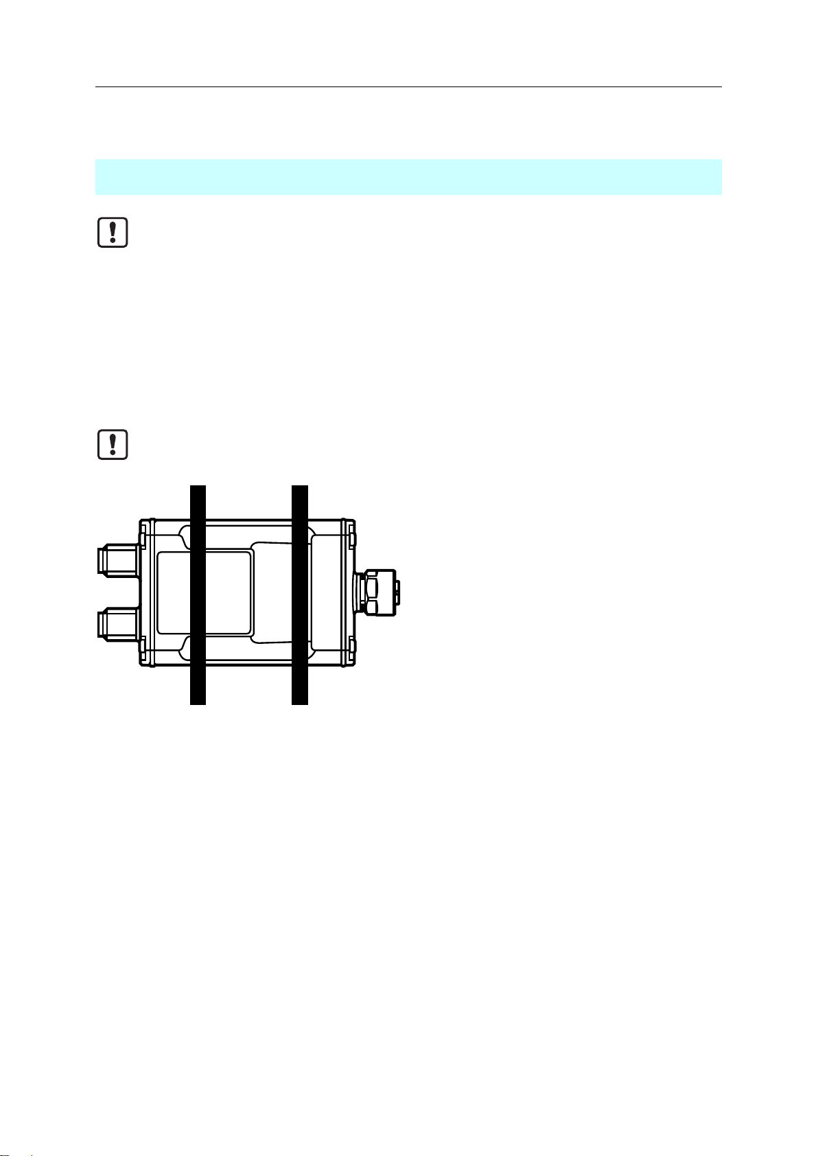
5Installation 9
5.1 Installing the device .............................................................................................................9
6Electrical connection 10
6.1 Overview............................................................................................................................11
6.2 Connecting the IO-Link device...........................................................................................11
6.3 Connecting the device .......................................................................................................11
7Operating and display elements 12
7.1 LED: PWR..........................................................................................................................12
7.2 LED: IO-Link.......................................................................................................................12
7.3 LED: DI/DO........................................................................................................................12
8Set-up 13
8.1 Installing LR DEVICE.........................................................................................................13
9Parameter setting 14
9.1 First steps...........................................................................................................................14
9.1.1 Online parameter setting............................................................................................................15
9.1.2 Offline parameter setting............................................................................................................15
9.2 Port 1: Configuring operating mode pin 4..........................................................................16
9.3 Port 1: Configuring device validation and data storage.....................................................17
9.3.1 Note: Device validation and data storage...................................................................................18