IFR STD-7000 Manual

Artisan Technology Group is your source for quality
new and certied-used/pre-owned equipment
• FAST SHIPPING AND
DELIVERY
• TENS OF THOUSANDS OF
IN-STOCK ITEMS
• EQUIPMENT DEMOS
• HUNDREDS OF
MANUFACTURERS
SUPPORTED
• LEASING/MONTHLY
RENTALS
• ITAR CERTIFIED
SECURE ASSET SOLUTIONS
SERVICE CENTER REPAIRS
Experienced engineers and technicians on staff
at our full-service, in-house repair center
WE BUY USED EQUIPMENT
Sell your excess, underutilized, and idle used equipment
We also offer credit for buy-backs and trade-ins
www.artisantg.com/WeBuyEquipment
REMOTE INSPECTION
Remotely inspect equipment before purchasing with
our interactive website at www.instraview.com
LOOKING FOR MORE INFORMATION?
Visit us on the web at www.artisantg.com for more
information on price quotations, drivers, technical
specications, manuals, and documentation
Contact us: (888) 88-SOURCE | sales@artisantg.com | www.artisantg.com
SM
View
Instra

I
I
I
I
I
I
I
I
111
I
I
I
I
I
I
I
tt
I
OPERATION I
MAINTENANCE
MANUAL
STANDARD
DIGITAL INTERFACE SYSTEM
STD-7000
PUBLISHED
BY
IFR
AMERICAS,
INC.
COPYRIGHT
©
IFR
Americas,
Inc.
1999
All
rights
reserved.
No
part
of
this
publication
may
be
reproduced,
stored
in a
retrieval
system,
or
transmitted
in
any
form
or
by
any
means,
electronic,
mechanical,
photocopying,
recording
or
otherwise
without
the
prior
permission
of
the
publisher.
10200
West
York
/
Wichita,
Kansas
67215
U.S.A.
/
(316)
522-4981
/
FAX
(316)
524-2623
Artisan Technology Group - Quality Instrumentation ... Guaranteed | (888) 88-SOURCE | www.artisantg.com

I
I
I
I
I
I
I
I
II
I
I
I
I
I
I
I
fI
I
I
Artisan Technology Group - Quality Instrumentation ... Guaranteed | (888) 88-SOURCE | www.artisantg.com

I
~~
OPERATION/MAINTENANCE
MANUAL
~'A
STD-7000
WARNING:
FIRST AID
HIGH VOLTAGE EQUIPMENT
RESCUE OF SHOCK VICTIMS
1.
DO
NOT
ATTEMPT
TO
PULL
OR
GRAB
THE
VICTIM
2.
IF
POSSIBLE,
TURN
OFF
THE
ELECTRICAL
POWER.
3.
IF
YOU
CANNOT
TURN
OFF
ELECTRICAL
POWER,
PUSH,
PULL
OR
LIFT
THE
VICTIM
TO
SAFETY
USING
A
WOODEN
POLE,
A
ROPE
OR
SOME
OTHER
DRY
INSULATING
MATERIAL.
1.
AS
SOON
AS
VICTIM
IS
FREE
OF
CONTACT
WITH
SOURCE
OF
ELECTRICAL
SHOCK,
MOVE
VICTIM
A
SHORT
DISTANCE
AWAY
FROM
SHOCK
HAZARD.
2.
SEND
FOR
DOCTOR
AND/OR
AMBULANCE.
3.
KEEP
VICTIM
WARM,
QUIET
AND
FLAT
ON
HIS/HER
BACK.
4.
IF
BREATHING
HAS
STOPPED,
ADMINISTER
ARTIFICIAL
RESUSCITATION.
STOP
ALL
SERIOUS
BLEEDING.
THIS
EQUIPMENT
CONTAINS
CERTAIN
CIRCUITS
AND/OR
COMPONENTS
OF
EXTREMELY
HIGH
VOLTAGE
POTENTIALS,
CAPABLE
OF
CAUSING
SERIOUS
BODILY
INJURY
OR
DEATH.
WHEN
PERFORMING
ANY
OF
THE
PROCEDURES
CONTAINED
IN
THIS
MANUAL,
HEED
ALL
APPLICABLE
SAFETY
PRECAUTIONS.
~-----
I
I
I
I
I
I
I
-
I
I
I
I
I
I
I
IArtisan Technology Group - Quality Instrumentation ... Guaranteed | (888) 88-SOURCE | www.artisantg.com

OPERATION/MAINTENANCE
MANUAL
STD-7000
CAUTION:
------
INTEGRATED
CIRCUITS
AND
SOLID
STATE
DEVICES
SUCH
AS
MOS
FETtS,
ESPECIALLY
CMOS
TYPES,
ARE
SUS-
CEPTIBLE
TO
DAMAGE
BY
ELECTROSTATIC
DISCHARGES
RECEIVED
FROM
IMPROPER
HANDLING,
THE
USE
OF
UNGROUNDED
TOOLS,
AND
IMPROPER
STORAGE
AND
PACKAGING.
ANY
MAINTENANCE
TO
THIS
UNIT
MUST
BE
PERFORMED
WITH
THE
FOLLOWING
PRECAUTIONS:
1.
BEFORE
USING
IN
ACIRCUIT,
KEEP
ALL
LEADS
SHORTED
TOGETHER
EITHER
BY
THE
USE
OF
VENDOR-SUPPLIED
SHORTING
SPRINGS
OR
BY
INSERTING
LEADS
INTO
A
CONDUCTIVE
MATERIAL.
2.
WHEN
REMOVING
DEVICES
FROM
THEIR
CONTAINERS,
GROUND
THE
HAND
BEING
USED
WITH
A
CONDUC-
TIVE
WRISTBAND.
3. TIPS
OF
SOLDERING
IRONS
AND/OR
ANY
TOOLS
USED
MUST
BE
GROUNDED.
4.
DEVICES
MUST
NEVER
BE
INSERTED
INTO
NOR
REMOVED
FROM
CIRCUITS
WITH
POWER
ON.
5.
PC
BOARD,
WHEN
TAKEN
OUT
OF
THE
SET,
MUST
BE
LAID
ON
A
GROUNDED
CONDUCTIVE
MAT
OR
STORED
IN
A
CONDUCTIVE
STORAGE
BAG.
6.
PC
BOARDS,
IF
BEING
SHIPPED
TO
THE
FACTORY
FOR
REPAIR,
MUST
BE
PACKAGED
IN
A
CONDUC-
TIVE
BAG
AND
PLACED
IN
A
WELL-CUSHIONED
SHIPPING
BOX.
I
I
I
I
I
I
I
I
-I
I
I
I
I
I
I
I
Artisan Technology Group - Quality Instrumentation ... Guaranteed | (888) 88-SOURCE | www.artisantg.com

I
I
,
I
I
I
I
I
I
I
--
I
I
I
I
I
I
I
I
~-
OPERATION/MAINTENANCE
MANUAL
~R
STD-7000
LIST
OF
EFFECTIVE
PAGES
---------------------
Cha£!~~LSe£!i~~L~~Q~~£l
E~~~
Date
--------
Ti t 1e
Pa
ge Apri 1
1/87
Copyright
Pa
ge Apri 1
1/87
Warning
Pa
ge Apri 1
1/87
Caution
Pa
ge Apri 1
1/87
Record
of
Revisions
Pa
ge Apri 1
1/87
List
of
Effective
Pa
ges 1
thru
2
April
1/87
Table
of
Contents
1
thru
2
April
1/87
Introduction
1
thru
2
April
1/87
I-Table
of
Contents
1
thru
4Apri 1
1/87
I-List
of
Illustrations
1
thru
2Apri 1
1/87
I-List
of
Tables
1
thru
2Apri 1
1/87
1-1-
11
thru
4Apri 1
1/87
1-
2-1
1
thru
8Apri 1
1/87
1- 2- 2 1
thru
6
April
1/87
1- 2- 3 1
thru
22
April
1/87
1-
3-1
1
thru
4Apri 1
1/87
1-4-1
1
thru
2Apri 1
1/87
1-5-1
1
thru
2
Ap
r i 1
1/87
2-Table
of
Contents
1
thru
4
April
1/87
2-List
of
Illustrations
1
thru
4
April
1/87
2-List
of
Tabl es 1
thru
2Apri 1
1/87
2-1-1
1
thru
2
April
1/87
2-
2-1
1
thru
30 Apri 1
1/87
2- 2- 2 1
thru
34 Apri 1
1/87
2- 2- 3 1
thru
10
Ap
r i 1
1/87
2- 2- 4 1
thru
62 Apri 1
1/87
2- 2- 5 1
thru
14 Apri 1
1/87
2- 2- 61
thru
12 Apri 1
1/87
2-
2-7
1
thru
34
Apri 1
1/87
2- 2- 8 1
thru
16
April
1/87
I-APPENDIX
A1
thru
6Apri 1
1/87
I-APPENDIX
B1
thru
4Apri 1
1/87
I-APPENDIX
C1
thru
2Apri 1
1/87
I-APPENDIX 01
thru
8
Ap
r i 1
1/87
I-APPENDIX E1
thru
2Apri 1
1/87
LIST
OF
EFFECTIVE
PAGES
Page 1
April
1/87
Artisan Technology Group - Quality Instrumentation ... Guaranteed | (888) 88-SOURCE | www.artisantg.com

~~
OPERATION/MAINTENANCE
MANUAL
Aft.
STD-7000
THIS
PAGE
INTENTIONALLY
LEFT
BLANK.
I
I
"I
I
I
I
I
I
I
-I
I
I
I
I
I
I
LIST
OF
EFFECTIVE
PAGES
Page 2 I
April
1/87
Artisan Technology Group - Quality Instrumentation ... Guaranteed | (888) 88-SOURCE | www.artisantg.com

I
~R~
OPERATION/MAINTENANCE
MANUAL
-,rA
STD-lOOO
'Ole
TABLE
OF
CONTENTS
-------------
I
I
I
I
I
I
I
lit
I
I
I
I
I
I
I
I
Title
Title
Page
Copyri
ght
Page
Caution
Page
Warning Page
Record
of
Revisions
List
of
Effective
Pages
Table
of
Contents
Introduction
Chapter
1
Description
Operation
Specifications
Shipping
Storage
Chapter
2
Servicing
Troubleshooting
Appendix A - Pin Out
Tables
Appendix B -
Test
Equipment
Requirements
Appendix C -
WRX/WRC-7708
GPIB
Command
Tables
Appendix D - STD-7000 I/O
Map
Appendix E - STD-7000
Memory
Map
Appendix F -
Abbreviations
1
1-1
1-
2
1-
3
1-4
1-
5
2
2-1
2-
2
TABLE
OF
CONTENTS
Pa
ge 1
Apri 1
1/87
Artisan Technology Group - Quality Instrumentation ... Guaranteed | (888) 88-SOURCE | www.artisantg.com

OPERATION/MAINTENANCE
MANUAL
STD-7000
THIS
PAGE
INTENTIONALLY
LEFT
BLANK.
I
I
I
I
I
I
I
III
I
I
I
I
I
I
I
TABLE
OF
CONTENTS
Page 2I
April
1/87
Artisan Technology Group - Quality Instrumentation ... Guaranteed | (888) 88-SOURCE | www.artisantg.com

I
I
I
I
I
I
I
I
-
I
I
I
I
I
I
I
I
~R~
OPERATION/MAINTENANCE
MANUAL
IrA STD-7000
.NC
INTRODUCTION
- STD-7000
STANDARD
DIGITAL
INTERFACE
SYSTEM
-------------------------------------------------
This
manual
contains
operation
and
maintenance
instructions
for
the
STD-7000
Bus
Controller
and
its
optional
Operator
Terminal
designated
as
the
Standard
Digital
Interface
(with
keypad)
System
(SDIS).
.
The
information
provided
in
this
manual
will
familiarize
the
operator/technician
with
the
STD-7000
to:
1.
Understand
general
operating
capabilities
of
each
unit
and
how
both
are
to
be
implemented
into
a
functional
test
system.
2.
Identify
and
understand
function
of
all
equipment
controls.
3.
Properly
interface
STD-7000
to
its
Operator
Terminal
and
pre-
pare
for
further
interface
to
accessory
test
equipment
and
UUT.
4.
Power-up
STD-7000/0perator
Terminal
and
understand
all
phases
of
start-up
operations.
5.
Certify,
test,
repair
or
replace
any
major
assembly
or
module
within
the
STD-7000
Bus
Controller.
6.
Sufficiently
understand
the
circuitry
and
principles
of
opera-
tion
of
the
optional
Operator
Terminal
and Keypad.
7.
Maintain
the
operation
of
each
unit
in
the
Standard
Digital
Interface
System
to
comply
with
expected
performance
standards
as
depicted
in
the
"specifications"
for
each
unit.
8.
Understand
the
principles
of
operation
as
they
relate
to
the
overall
operation
of
the
system,
as
well
as
to
individual
circuits.
Due
to
the
diverse
range
of
applications
for
which
this
equipment
can be
used,
this
manual does
not
contain
detailed
operating
instructions
for
any
specific
application.
After
thoroughly
fami-
liarizing
oneself
with
all
contents
of
this
manual and
sequentially
performing
all
required
installation/operation
procedures,
operator
should
refer
to
appropriate
System
Operation
Manual
for
detailed
operating
instructions.
INTRODUCTION
Pa
ge 1
April
1/87
Artisan Technology Group - Quality Instrumentation ... Guaranteed | (888) 88-SOURCE | www.artisantg.com

~R~
OPERATION/MAINTENANCE
MANUAL
7rA
STD-7000
'NC
The
information
in
this
manual
applies
to
each
unit
in
the
Standard
Digital
Interface
System
(SOlS),
which
includes
the
STD-7000 Bus
Controller
Unit,
ESP
6515
CRT
Display
Terminal,
CRT
Interface,
Numeric Keypad and
associated
interface
cabling.
The
information
is
relative
to
the
mechanical
and
electrical
characteristics
of
the
Standard
Digital
Interface
System
(SOlS).
This
manual
contains
requirements
for
evaluating
the
SOlS
during
annual
certification
or
at
any
time
performance
is
in
doubt.
Even
though
its
history
indi-
cates
a
high
reliability
rate,
the
SOlS
may
require
"in
depth"
maintenance,
such
as
prudent
testing,
troubleshooting
and
or
exten-
sive
repair.
With
this
in
mind,
the
material
and
procedures
in
this
manual
will
be
helpful
to
the
technician
during
the
main-
tenance
process
from
problem
isolation
to
final
repair.
INTRODUCTION
Pa
ge 2
Apri 1
1/87
I
I
I
I
I
I
I
I
til
I
I
I
I
I
I
I
I
Artisan Technology Group - Quality Instrumentation ... Guaranteed | (888) 88-SOURCE | www.artisantg.com

---------------------------------------------------------
I-TABLE
OF
CONTENTS
Pa
ge 1
April
1/87
~R~
OPERATION
MANUAL
~rA
STD-7000
.-
SECTION
1 -
DESCRIPTION
1
1
1
2
2
2
2
2
1
1
1
3
3
3
4
5
5
1
1
1
1
1
2
2
3
3
3
3
3
3
4
4
1-1
1-1-
1
1-1-
1
1-1-
1
1-
1-1
1- 1- 1
1- 1- 1
1- 1- 1
1- 1- 1
1-
2
1-
2-
1
1-
2-1
1-
2-1
1-
2-1
1-
2-1
1-
2-
1
1-
2-1
1-
2-1
1-
2-1
1-
2-
2
1-
2-
2
1-
2-
2
1-
2-
2
1-
2-
2
1-
2-
2
1-
2-
2
1-
2-
2
1-
2-
2
1-
2-
2
1-
2-
2
1-
2-
2
1-
2-
2
1-
2-
2
1-
2-
2
CHAPTER
ONE
STQ~ZQQQ_~TANDARQ_QIQlI~h_llilfRf~ff_~r~If~
QfIRATIQ~MANQ~h
IABhf-Qf_£Q~IfNI~
£h~~L~~!iQ~L~~£I~£!
Installation
A. Gene"ral
(1)
Safety
Precautions
(2)
Equipment
Inspection
(3)
Power
Requirements
(4)
Installation
Equipment
(5)
Bench/Rack
Installation
B. System
Interface
(1)
System
Interface
Procedure
Description
of
Controls,
Connectors
and
Indicators
A. STD-7000
Front
Panel
(1)
Magnetic
Tape
Transport
(2)
Keypad Mount
(3)
Reset
Switch
(4)
Tape
Cassette
Eject
Button
(5)
AC
Power
Switch
B. Rear Panel
(1)
Discrete
Functions
Interface
Connector
(2)
CRT
Power
Receptacle
(3)
STD-7000 Power
Receptacle/Line
Fuse Compartment
(4)
RS-232C
Interface
Connector
(5)
IFR Bus
Interface
Connector
(6)
IEEE-488
Bus
Interface
Connector
(7)
IEEE-488
Address
Switch
2•
Tit1e
SECTION
2 -
OPERATION
1•
1.
General
2.
Functional
A. STD-7000 Bus
Controller
B.
Operator
Terminal
3.
Functional
Block Diagram
4.
Software
Implementation
A.
Magnetic
(or
"Per s onal tt
y'")
Tape
B.
PROM
Card
Memory
(Optional)
I
~
I
I
I
I
I
I
I
I
I
-
I
I
I
I
I
I
I
Artisan Technology Group - Quality Instrumentation ... Guaranteed | (888) 88-SOURCE | www.artisantg.com

~
I
I-TABLE
OF
CONTENTS
Pa
ge 2 I
April
1/87
1.
STD-7000
Specifications
A.
Bus
Characteristics
B. Rear Panel
Interfaces
C.
Processor
System
D.
Magnetic
Tape
Transport
E.
Physical
Characteristics
F. Opti onal
Peri
pheral
s
I
I
I
I
I
I
I
I
-.
I
I
I
I
I
I
I
1
1
2
2
3
3
4
16
20
f!S~
3
3
3
4
4
5
5
5
5
5
6
6
6
6
1
1
1
1
1
1
2
2
2
2
3
7
7
11
11
11
12
13
15
1-
2-
2
1-
2-
2
1-
2-
2
1-
2-
2
1-
2-
2
1-
2-
2
1-
2-
2
1-
2-
2
1-
2-
2
1-
2-
2
1-
2-
2
1-
2-
2
1-
2-
2
1-
2-
2
1-
2-
3
1-
2-
3
1-
2-
3
1-
2-
3
1-
2-
3
1-
2-
3
1-
2-
3
1-
2-
3
1-
2-
3
1-
2-
3
1-
2-
3
1-
2-
3
1-
2-
3
1-
2-
3
1-
2-
3
1-
2-
3
1-
2-
3
1-
2-
3
1-
2-
3
1-
2-
3
1-
2-
3
1-
3
1-
3-1
1-
3-1
1-
3-1
1-
3-1
1-
3-1
1-
3-1
1-
3-1
OPERATION
MANUAL
STD-7000
.-
Ti
tl
e
C. ESP-6515
CRT
Display
Terminal
(1)
CRT
Power
Switch
(2)
CRT
Keyboard
D.
Numeric Keypad
(1)
Basic
Keypad
Operations
E.
CRT
Interface
Front
Panel
(1)
Terminal
Connector
(2)
Keypad
Connector
(3)
STD-7000
Connector
(4)
Power
Indicator
Lamp
F.
CRT
Interface
Rear Panel
(I)
Fuse
(2)
Power
Input
Connector
(3)
Power
Output
Connector
.
3.
General
Operati
ng
Procedures
A. Power-Up
Behavior
(1)
Automatic
Start-Up
Routine
(2)
Diagnostic
Test
Program
(3)
Tape Program
{4}
PROM
Program
B. IEEE-488 Address
Switch
Settings
C. IEEE-488 Address
Switch
Functions
(I)
Selection
of
Start-Up
Routines
{2}
Selection
of
Bus
Address
D.
Automatic
Start-Up
Routine
E.
Set-Up
Mode
.
{I}
Set-Up
Mode
Procedure
F.
Personality
Display
(1)
Men
uFo
rm
at
(2)
Reset
vs.
Personality
Menus
{3}
Personality
Menus
(4)
Master
Menu
{5}
Function
Control
Menu
(6)
Data
Fields
(Identification
and
Manipulation)
(7)
Data
Entry
Format
SECTION
3 -
SPECIFICATIONS
---------------
Artisan Technology Group - Quality Instrumentation ... Guaranteed | (888) 88-SOURCE | www.artisantg.com

1.
STD-7000
Shipping/Repacking
A.
Shipping
Information
B. Repacking
Procedure
I
.,
,
I
I
I
I
I
I
I
•
I
I
I
I
I
I
I
.-
Title
SECTION
4 -
SHIPPING
SECTION
5 -
STORAGE
1.
Storage
Precautions
OPERATION
MANUAL
STD-7000
£h~£!~~L~~£!i~~L~~£i~£!
1-
4
1-
4-1
1-4-1
1-
4-1
1-
5
1-
5-1
1
1
1
1
I-TABLE
OF
CONTENTS
Pa
ge 3
April
1/87
Artisan Technology Group - Quality Instrumentation ... Guaranteed | (888) 88-SOURCE | www.artisantg.com

-----------------------~---------------.
OPERATION
MANUAL
STD-7000
THIS
PAGE
INTENTIONALLY
LEFT
BLANK.
1-TABLE
OF
CONTENTS
Page 4
April
1/87
I
-;
..
I
I
I
I
I
I
I
III
I
I
I
I
I
Artisan Technology Group - Quality Instrumentation ... Guaranteed | (888) 88-SOURCE | www.artisantg.com

~R~
OPERATION
MANUAL
-,rA
STD-7000
INC
LIST
OF
ILLUSTRATIONS
---------------------
f!.9.~
3
5
7
4
6
1
2
3
4
5
6
2
6
7
7
7
8
8
8
8
9
13
15
16
17
18
19
2
1-
2-
3
1-
2-
3
1-
2-
3
1-
2-
3
1-
2-
3
1-
2-
3
1-
2-
3
1-
2-
3
1-
2-
3
1-
2-
3
1-
2-
3
1-
2-
3
1-
2-
3
1-
2-
3
1-
2-
3
1-
4-1
£~£!~~L~£!i£~L~g£~~£!
1- 1- 1
1- 1- 1
1- 1- 1
1-
2-
1
1-
2-
1
1-
2- 2
1-
2-
2
1-
2-
2
1-
2-
2
1-
2-
2
1-
2-
2
1-
2-
3
Ti t1e
STD-7000
Functional
Block Diagram
STD-7000
Composite
CRT
Interface
Composite
Recommended
Installation
Configuration
System
Interface
Diagram
STD-7000
Front
Panel
STD-7000 Rear
Panel
CRT
Display
Terminal
(Front
View)
16-Key Numeric Keypad (Top View)
CRT
Interface
Front
Panel
CRT
Interface
Rear Panel
STD-7000 IEEE-488 Address
Switch
Settings
Automatic
Start-Up
Routine
(Sequence
of
Operation)
.
Directory
Menu
Display
Menu
General
Menu
Comm
Menu
Printer
Menu
Keyboard
Menu
Tab
Menu
Response
Menu
Master
Menu
(Typical
Display)
Function
Control
Menu
(Typical
Display)
Function
Control
Menu
(Binary
Data
Fields)
Function
Control
Menu
(Numeric Data
Fields)
Function
Control
Menu
(Alpha Data
Fields)
Function
Control
Menu
(Alphanumeric
Data
Fields)
Repacking
Procedure
I
I
I
I
I
I
I
I
.-
I
I
I
I
I
I
I
I
I-LIST
OF
ILLUSTRATIONS
Pa
ge 1
April
1/87
Artisan Technology Group - Quality Instrumentation ... Guaranteed | (888) 88-SOURCE | www.artisantg.com

OPERATION
MANUAL
5TD-7000
I
THI5
PAGE
INTENTIONALLY
LEFT
BLANK.
I
I
I
I
I
I
I
til
I
I
I
I
I
I
I
I-LIST
OF
ILLUSTRATIONS
Page 2 I
April
1/87
Artisan Technology Group - Quality Instrumentation ... Guaranteed | (888) 88-SOURCE | www.artisantg.com

-------------------------------------~------~
-~~
I
!PR~
OPERATION
MANUAL
-,rA
STD-7000
'000
LIST
OF
TABLES
I
I
I
I
I
I
I
.-
I
I
I
I
I
I
I
Ti
tl
e
Rack
Mounting
Kits
Segment
Positioning
£h!£!~rL~~£!iQ~LSubj~£!
1-
2-1
1-
2-
3
f!.9.~
4
2
I
1-LIST
OF
TABLES
Pa
ge 1
Apr;
1
1/87
Artisan Technology Group - Quality Instrumentation ... Guaranteed | (888) 88-SOURCE | www.artisantg.com

OPERATION
MANUAL
STD-7000 I
THIS
PAGE
INTENTIONALLY
LEFT
BLANK.
I
I
I
I
I
I
I
til
I
I
I
I
I
I
I
I-LIST
OF
TABLES
Page 2
April
1/87
I
Artisan Technology Group - Quality Instrumentation ... Guaranteed | (888) 88-SOURCE | www.artisantg.com

2•
£.Q!!..£liQ!!.~l
Until
programmed
for
a
specific
appl
ication
and
implemented
within
a
test
system
thru
an
appropriate
interface,
the
capabi-
lities
of
the
SOlS
are
limited
to
normal
power-up
functions
.
This
manual
therefore
describes
the
capabilities
of
the
SOlS on
a
general
level
only,
as
they
exist
within
any
ARINC
700
series
test
system.
Detailed
operation
of
the
system,
when programmed
for
specific
applications,
are
described
within
separate
System
Operation
Manuals.
I
I
I
I
I
I
I
I
.-
I
I
I
I
I
1 •
OPERATION
MANUAL
STD-7000
SECTION
1 -
DESCRIPTION
General
-----
The
Standard
Digital
Interface
System (SOlS)
is
comprised
of
the
STD-7000 Bus
Controller
and
Operator
Terminal
(CRT
Display,
CRT
Interface
and Numeric
Keypad).
These
components
make up a
standard
hardware
configuration
com-
mon
to
several
different
ARINC
compatible
avionics
test
systems.
The
primary
function
of
the
configuration
is
to
generate
and
receive
ARINC
429/453
buses
and
display
the
con-
tents
of
those
buses
on a
CRT,
thereby
permitting
an
operator
to
verify
the
integrity
of
the
system
under
test.
A
prime
design
goal
of
the
SOlS
is
to
provide
a
clear
and
simple
format
for
monitoring
and
controlling
ARINC
bus
activity
from and
to
the
unit
under
test
(UUT),
while
allowing
the
operator
to
interpret
and
manipulate
data
with
aminimum
of
effort.
A. STD-7000 Bus
Controller
The STD-7000
is
a
programmable
ARINC
bus
controller
designed
to
control
serial
bus
communication
within
ARINC
700
series
avionics
test
systems.
The
controller
contains
the
following
bus
provisions:
(1)
Six
(6)
programmable
high/low
speed
ARINC
429 I/O
buses
and
three
(3)
programmable
very
high
speed
ARINC
453 I/O
buses.
(2)
One
(1) IFR
I/O
bus used
for
interface
of
auxiliary
IFR
test
equipment.
(3)
One
(1)
IEEE
Standard
488-1978
bus
for
interface
of
an
external
ATE
Controller.
(4)
One
(1)
EIA
RS232C
bus
for
interface
of
Operator
Term
ina
1•
1-1-1
Page 1
Apr; 1
1/87
Artisan Technology Group - Quality Instrumentation ... Guaranteed | (888) 88-SOURCE | www.artisantg.com
Table of contents
Popular Controllers manuals by other brands

AutomationDirect
AutomationDirect DL05 user manual
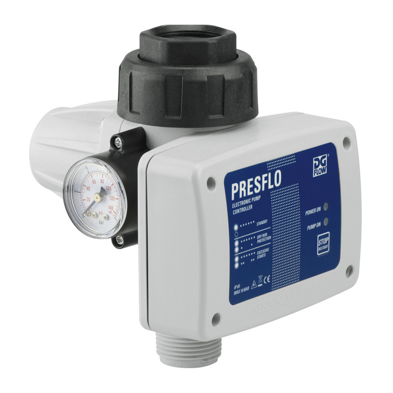
DGFLOW
DGFLOW PRESFLO user manual
AutomationDirect
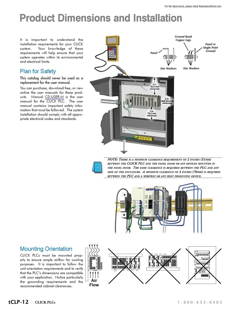
AutomationDirect CLICK Product Dimensions and Installation

Fairchild
Fairchild 1600A Installation, operation and maintenance instructions
IFM Electronic
IFM Electronic AS interforce AC1303 installation instructions
ABB
ABB ACS880-07 Hardware manual
