manuals.online logo
Brands
  1. Home
  2. •
  3. Brands
  4. •
  5. Sanyo
  6. •
  7. Controllers
  8. •
  9. Sanyo VSP-3000 User manual

Sanyo VSP-3000 User manual

FILE NO.
REFERENCE No.SM5310743
L8CSE/WA (R)
NOTE: 1. Parts order must contain model number, part number, and description.
2. Substitute parts may be supplied as the service parts.
3. N.S.P. : Not available as service parts.
Design and specifications are subject to change without notice.
SERVICE MANUAL
System Controller
The components designated by a symbol ( ! ) in this schematic diagram designates components whose value are of
special significance to product safety. Should any component designated by a symbol need to be replaced, use only the
part designated in the Parts List. Do not deviate from the resistance, wattage, and voltage ratings shown.
PRODUCT SAFETY NOTICE
RoHS
This product does not contain any hazardous substances prohibited by the RoHS Directive.
WARNING
You are requested to use RoHS compliant parts for maintenance or repair.
You are requested to use lead-free solder.
(This product has been manufactured using lead-free solder. Be sure to follow the warning given on page 2 when carrying
out repair work.)
CONTENTS
1. DISASSEMBLY .................................3
2. BASIC SETTING FOR JOYSTICK......5
3. PARTS LIST ....................................6
VSP-3000
(Product Code : 117 523 64)
(U.S.A., Canada, Brazil)
(Europe, U.K.,Asia, Africa)
(Otheania)
(General)
SPECIFICATIONS
Communication formar : RS485, RS-422
Keyboard : 29 keys
Joystick : Three-axis joystick (pan/ tilt/ zoom)
Control communication terminal : Tx1, Tx2, Tx3, TRx
Protocol : SSP, H-SSP, Pelco-D
USB mouse port : Compatible with DVRs with mouse function
Communication speed : 2400, 4800, 9600, 19200, 38400, 57600 bps
Maximum number of connectable units :
Total : 256 units
Cameras : SSP/HSSP:127 units, Pelco-D:255 units
Controllers : 5 units
Digital videorecorders : 99 units
Operating environment : Temperature 5 - 40°C Humidity 80 % or less
Storage environment : Temperature -20 - 60°C Humidity 80 % or less
Power source : Input voltage : 100 - 240V AC, 50/60 Hz
(AC adapter) Output voltage : 12 V DC
Current consumption : 0.2 A
Weight : 750g
-2 -
WARNING
Do not use solder containing lead.
This product has been manufactured using lead-free
solder in order to help preserve the environment.
Because of this, be sure to use lead-free solder when
carrying out repair work, and never use solder
containing lead.
Lead-free solder has a melting point that is 30 - 40°C (86 -
104°F) higher than solder containing lead, and moreover it
does not contain lead which attaches easily to other metals.
As a result, it does not melt as easily as solder containing
lead, and soldering will be more difficult even if the
temperature of the soldering iron is increased.
The extra difficulty in soldering means that soldering time
will increase and damage to the components or the circuit
board may easily occur.
Because of this, you should use a soldering iron and
solder that satisfy the following conditions when carrying out
repair work.
Soldering iron
Use a soldering iron which is 70 W or equivalent, and
which lets you adjust the tip temperature up to 450°C
(842°F). It should also have as good temperature recovery
characteristics as possible.
Set the temperature to 350°C (662°F) or less for chip
components, to 380°C (716°F) for lead wires and similar,
and to 420°C (788°F) when installing and removing shield
plates.
The tip of the soldering iron should have a C-cut shape or
a driver shape so that it can contact the circuit board as flat
or in a line as much as possible.
Solder
Use solder with the metal content and composition ratio by
weight given in the table below. Do not use solders which
do not meet these conditions.
Lead-free solder is available for purchase as a service tool.
Use the following part number when ordering:
Part name: Lead-free solder with resin (0.5 mm dia., 500 g)
Part number: VJ8-0270
Metal content Tin (Sn) Silver (Ag) Copper (Cu)
Composition
ratio by weight 96.5% 3.0% 0.5%
Note:
If replacing existing solder containing lead with lead-free
solder in the soldered parts of products that have been
manufactured up until now, remove all of the existing solder
at those parts before applying the lead-free solder.
-3 -
1
4
3
2
5
55
4
9
8
6
7
11
12
10
13
1. DISASSEMBLY
1-1. REMOVAL OF LOWER CASE (CASE BOTTOM) AND JOY STICK
1. Screw 3 x 6
2. Battery cover (Cover battery)
3. Battery DC9V
4. Rubber foot
5. Five screws 3 x 10
6. Battery cable connector
7. Screw 3 x 10
8. Cable tie
9. Lower case (Case bottom)
10. Four screws
11. Joy stick cover
12. Joy stick
13. Window
-4 -
1-2. REMOVAL OF UPPER CASE (CASE TOP) AND PCB ASSY MAIN
1-3. DIMENSIONS
Unit: mm
180
280
100
2
1
3
4
5
7
6
1. LCD cable
2. Four screws 3 x 10
3. Two screws 3 x 6
4. LCD module
5. Upper case (Case top)
6. Key rubber (Rubber keypad)
7. PCB assy MAIN
-5 -
2. BASIC SETTING FOR JOYSTICK
After assembling the product, it has to be set below
(especially, the AS of Main Board or Joystick)
2-1. JOYSTICK CALIBRATION:
Push No.3 + SUB MENU (3 sec), the it move to JOYSTICK CALIBRATION MODE
2-2. KEY TEST
Push No.3 + SUB MENU (3 sec),test each key button with LCD indication.
2-3. Renew the Password :
Put the PASS WORD5534 for master p/w and set the new one.
1
2
3
4
5
6
7
Set the center of JOYSTICK
(PushENT without joystick movement)
Set the left end of JOYSTICK
(PushENT with joystick move left end)
Set the right end of JOYSTICK
(PushENT with joystick move right end)
Set the up end of JOYSTICK
(PushENT with joystick move up end)
Set the down end of JOYSTICK
(PushENT with joystick move down end)
Set the WIDE end of JOYSTICK - counterclockwise
(PushENT with joystick move WIDE end)
Set the TELE end of JOYSTICK -clockwise
(PushENT with joystick move TELE end)
PTZ OFFSET
PAN LEFT
PAN RIGHT
TILT UP
TILT DOWN
ZOOM WIDE
ZOOM TELE
NO Joystick setting point Method
6
LOCATION PARTS NO. DESCRIPTION LOCATION PARTS NO. DESCRIPTION
3. PARTS LIST (R)
ACCESSORIES & PACKING MATERIALS
WNSAS-05 MANUAL OWNERS WTX-1200A
English,German,French,Spanish,
Chinese (Simplified),Japanese
WNSAS-06 AKZ1550-8P TERMINAL
WNSAS-07 ADAPTOR 100V~240V (SANYO) SA06L1113
12V/1.25A
(INCLUDING 3 KINDS OF POWER CODE)
WNSAS-08 CONNECTOR JACK DEK 301-6C
(JUNCTION BOX)
WNSAS-09 CABLE RJ-11 6P WTX-2000
WNSAS-10 CABLE USB WTX-1200
WNSAS-04 PACKING MATERIAL
BOX GIFT WTX-1200A (SANYO)
PE FOAM TOP WTX-1200 (SANYO)
PE FOAM BOTTOM WTX-1200
CABINET & CHASSIS PARTS
1 WNSAS-01 ASSY JOY STICK WJ-201 (INCLUDE SCREWS)
2 WNSAS-02 ASSY LCD MODULE
(INCLUDE METAL PLATE AND SCREWS)
3 WNSAS-03 ASSY CASE TOP WTX-1200 (SANYO)
(INCLUDE SCREWS, RUBBER FOOT)
WINDOW WTX-1200 SANYO
CASE BOTTOM WTX-1200 (SANYO)
COVER BATTERY WTX-1200 (SANYO)
RUBBER FOOT WTX-1200
RUBBER KEYPAD WTX-1200 (SANYO)
4 WNSAS-11 PCB ASSY MAIN WTX-1200A (ROHS)
(CABLE HARNESS, TERMINAL 2P)
7
4
2
3
1
L8CSE/WA(MS)
Apr./’08
SANYO Electric Co., Ltd.
Osaka, Japan

Other Sanyo Controllers manuals

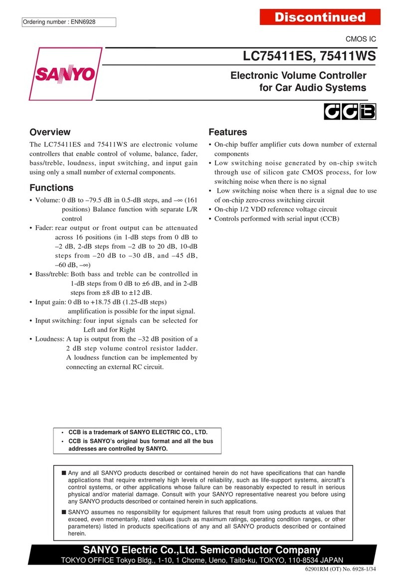
Sanyo LC75411ES User manual

Sanyo

Sanyo LC75411ES User manual

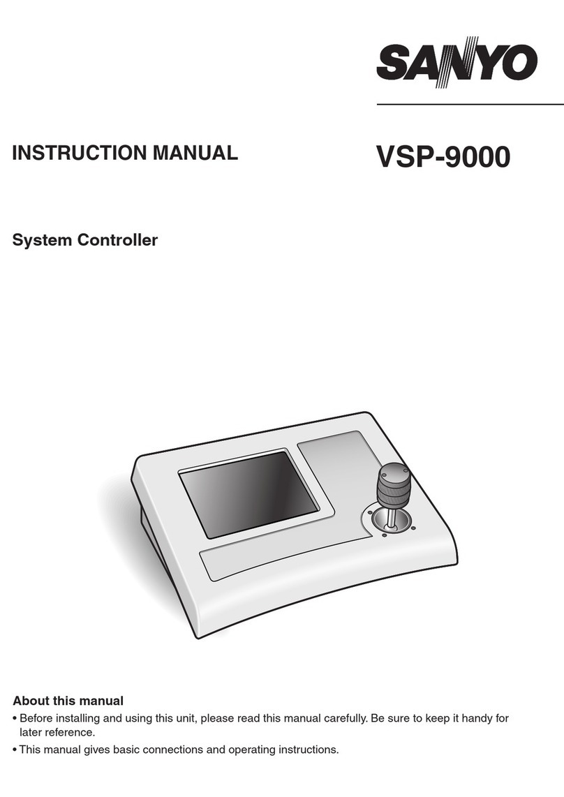
Sanyo VSP-9000 User manual

Sanyo

Sanyo VSP-9000 User manual

Sanyo SHA TM64 AGB User manual

Sanyo

Sanyo SHA TM64 AGB User manual

Popular Controllers manuals by other brands

Milton Roy LMI Liquitron DP5000 Series instruction sheet

Milton Roy

Milton Roy LMI Liquitron DP5000 Series instruction sheet

14POINT7 Edge AFR manual

14POINT7

14POINT7 Edge AFR manual

WebWay Mini quick start guide

WebWay

WebWay Mini quick start guide

X-keys XKE-40 Series product manual

X-keys

X-keys XKE-40 Series product manual

Danfoss AK-PC 420 instructions

Danfoss

Danfoss AK-PC 420 instructions

Nexmosphere XPERIENCE XC-938 quick start guide

Nexmosphere

Nexmosphere XPERIENCE XC-938 quick start guide

Embedded Systems LogicMachine5 manual

Embedded Systems

Embedded Systems LogicMachine5 manual

Suhr microMIDI Control user guide

Suhr

Suhr microMIDI Control user guide

Hydthc CHC-1000S user manual

Hydthc

Hydthc CHC-1000S user manual

Parker PTR Series Maintenance Instructions & Parts List

Parker

Parker PTR Series Maintenance Instructions & Parts List

LOVATO ELECTRIC RGAM 10 instruction manual

LOVATO ELECTRIC

LOVATO ELECTRIC RGAM 10 instruction manual

Morningstar SUNSAVER DUO Installation and operation manual

Morningstar

Morningstar SUNSAVER DUO Installation and operation manual

Vacon NX series Applications manual

Vacon

Vacon NX series Applications manual

LAW-CHAIN LF-318 quick start guide

LAW-CHAIN

LAW-CHAIN LF-318 quick start guide

CHINT NS2-80B User instruction

CHINT

CHINT NS2-80B User instruction

ZALMAN ZM-MFC3 user manual

ZALMAN

ZALMAN ZM-MFC3 user manual

Vertiv Liebert Load Bus Sync Controller user manual

Vertiv

Vertiv Liebert Load Bus Sync Controller user manual

Gossen MetraWatt R2900 operating instructions

Gossen MetraWatt

Gossen MetraWatt R2900 operating instructions

manuals.online logo
manuals.online logoBrands
  • About & Mission
  • Contact us
  • Privacy Policy
  • Terms and Conditions

Copyright 2025 Manuals.Online. All Rights Reserved.