IFR FM/AM-1200A User manual

-~
ARTISAN
®
~I
TECHNOLOGY
GROUP
Your definitive source
for
quality
pre-owned
equipment.
Artisan Technology
Group
Full-service,
independent
repair
center
with
experienced
engineers
and
technicians
on staff.
We
buy
your
excess,
underutilized,
and
idle
equipment
along
with
credit
for
buybacks
and
trade-ins
.
Custom
engineering
so
your
equipment
works
exactly as
you
specify.
•
Critical
and
expedited
services
•
Leasing
/
Rentals/
Demos
• In
stock/
Ready-to-ship
•
!TAR-certified
secure
asset
solutions
Expert
team
ITrust
guarantee
I
100%
satisfaction
All
tr
ademarks,
br
a
nd
names, a
nd
br
a
nd
s a
pp
earing here
in
are
th
e property of
th
e
ir
r
es
pecti
ve
ow
ner
s.
Visit our website - Click HERE

OPERATION
MANUAL
FM/
AM-12005/
A
COMMUNICATIONS
SERVICE
MONITOR
10200
West
York
Street/Wichlta,KS
67215
U.S.A./(316)
522-4981/TWX
910-741-6952
1002-5501-000

PUBLISHED
BY
IFR
SYSTEMS,
INC.
Wichita,
Kansas
COPYRIGHT© 1988
by
IFR
SYSTEMS,
INC.
All
rights
reserved.
Printed
in
the
United
States
of
America.
No
part
of
this
publication
may
be
reproduced,
stored
in
a
retrieval
system,
or
transmitted
in
any form
or
by
any
means,
electronic,
mechanical,
photo-
copying,
recording
or
otherwise
without
the
prior
permission
of
the
publisher.
Manual
Part
Number:
1002-5501-000

WARNING:
HIGH VOLTAGE EQUIPMENT
THIS
EQUIPMENT
CONTAINS
CERTAIN
CIRCUITS
AND/OR
COMPONENTS
OF
EXTREMELY
HIGH
VOLTAGE
POTENTIALS.
CAPABLE
OF
CAUSING
SERIOUS
BODILY
INJURY
OR
DEATH.
WHEN
PERFORMING
ANY
OF
THE
PROCEDURES
CONTAINED
IN
THIS
MANUAL.
HEED
ALL
APPLICABLE
SAFETY
PRECAUTIONS.
RESCUE OF SHOCK VICTIMS
1.
DO
NOT
ATTEMPT
TO
PULL
OR
GRAB
THE
VICTIM
2.
IF
POSSIBLE.
TURN
OFF
THE
ELECTRICAL
POWER.
3.
IF
YOU
CANNOT
TURN
OFF
ELECTRICAL
POWER.
PUSH,
PULL
OR
LIFT
THE
VICTIM
TO
SAFETY
USING
A
WOODEN
POLE.
A
ROPE
OR
SOME
OTHER
DRY
INSULATING
MATERIAL.
FIRST
AID
1.
AS
SOON
AS
VICTIM
IS
FREE
OF
CONTACT
WITH
SOURCE
OF
ELECTRICAL
SHOCK.
MOVE
VICTIM
A
SHORT
DISTANCE
AWAY
FROM
SHOCK
HAZARD.
2.
SEND
FOR
DOCTOR
AND/OR
AMBULANCE.
3.
KEEP
VICTIM
WARM.
QUIET
AND
FLAT
ON
HIS/HER
BACK.
4.
IF
BREATHING
HAS
STOPPED
•
ADMINISTER
ARTIFICIAL
RESUSCITATION.
STOP
ALL
SERIOUS
BLEEDING.
-
,
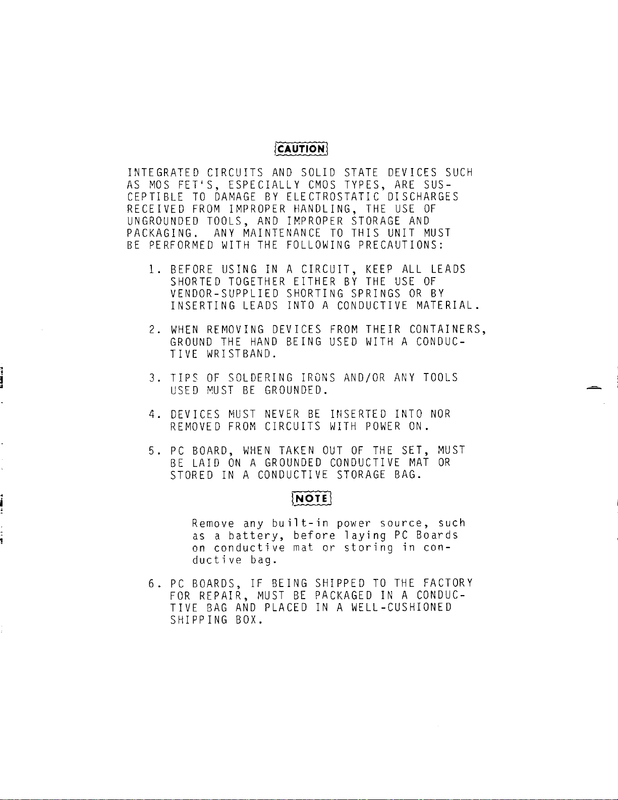
fcAUT(ON\
INTEGRATED
CIRCUITS
AND
SOLID
STATE
DEVICES
SUCH
AS
MOS
FET'S,
ESPECIALLY
CMOS
TYPES,
ARE
SUS-
CEPTIBLE
TO
DAMAGE
BY
ELECTROSTATIC
DISCHARGES
RECEIVED
FROM
IMPROPER
HANDLING,
THE
USE
OF
UNGROUNDED
TOOLS,
AND
IMPROPER
STORAGE
AND
PACKAGING.
ANY
MAINTENANCE
TO
THIS
UNIT
MUST
BE
PERFORMED
WITH
THE
FOLLOWING
PRECAUTIONS:
1.
BEFORE
USING
IN
A
CIRCUIT,
KEEP
ALL
LEADS
SHORTED
TOGETHER
EITHER
BY
THE
USE
OF
VENDOR-SUPPLIED
SHORTING
SPRINGS
OR
BY
INSERTING
LEADS
INTO
A
CONDUCTIVE
MATERIAL.
2.
WHEN
REMOVING
DEVICES
FROM
THEIR
CONTAINERS,
GROUND
THE
HAND
BEING
USED
WITH
A
CONDUC-
TIVE
WRISTBAND.
3.
TIPS
OF
SOLDERING
IRONS
AND/OR
ANY
TOOLS
USED
MUST
BE
GROUNDED.
4.
DEVICES
MUST
NEVER
BE
INSERTED
INTO
NOR
REMOVED
FROM
CIRCUITS
WITH
POWER
ON.
5.
PC
BOARD,
WHEN
TAKEN
OUT
OF
THE
SET,
MUST
BE
LAID
ON
A
GROUNDED
CONDUCTIVE
MAT
OR
STORED
IN
A
CONDUCTIVE
STORAGE
BAG.
[NOTE\
Remove any
built-in
power
source,
such
as a
battery,
before
laying
PC
Boards
on
conductive
mat
or
storing
in
con-
ductive
bag.
6.
PC
BOARDS,
IF
BEING
SHIPPED
TO
THE
FACTORY
FOR
REPAIR,
MUST
BE
PACKAGED
IN
A
CONDUC-
TIVE
BAG
AND
PLACED
IN
A
WELL-CUSHIONED
SHIPPING
BOX.

~
LIST
OF
EFFECTIVE
PAGES
The
manual
pages
listed
below
are
identified
by
revision
number.
Those
pages
affected
by
the
current
change
or
revision
are
so
identified
by
the
current
revision
number
and
an
asterisk
(*).
Original
0
March
1.
1986
Revision
. . . . 1
..
. .
September
22.
1986
Revision
2
..
June
22.
1987
Revision
..
3
September
15.
1987
Revision
..
4 Apr i 1
15.
1988
Revision
..
. . 5
November
1 .
1988
Revision
6
November
15.
1989
Revision
.. 7
...
Apr i 1
17.
1990
Revision
. . 8
..
September
1 .
1991
TOTAL
NUMBER
OF
PAGES
IN
THIS
MANUAL
IS
288;
CONSISTING
OF
THE
FOLLOWING:
Pg.
No.
Change
No.
Pg.
No.
Change
No.
Ti t 1e
Page
......
....
0
4-8
thru
4-11
.
..
. . 2
Copyright
Page
....
4
4-12
............
•
••
0 3
Warni
ng
Page
.......
0
4-13
thru
4-
14
....
2
Caution
Page
.. .. . . 0
4-
15
..
0
•••••••••••••
0
*A
..
.. . . .. . . . . . . ...... 8
4-
16
.............
... 2
*B
.. 0
•••••••••••••
.... 8
4-17
thru
4-17a
. . 5
i . . .. .... . . . . . . .. . . .. 0
4-17b
Bl
ank
.
.....
2
i i
.......
• • • • • • • • •
0.
0 2
4-18
.....
•••
0
••••
0
..
2
1 1 1
thru
Xi
i
...
. . . . 6
4-19
thru
4-21
. . 0
1- 1
thru
1-
3
.......
5
4-22
thru
4-24a
.. 2
1-
4 Bl
ank
• 0
•••••••••
2
4-24b
Bl
ank
.
....
. . 2
2-1
......
. . . . . . . . . ... 2
4-2
5
.............
. .. 2
2-
2
thru
2-4
...
0
•••
5
4-2
6
................
0
2-
5
••
0
••••
. .. . . . . . .. . 2
4-27
thru
4-
29
....
2
2-
6 .. . .. .• • • • • 0
..
•
0.
0 5
4-3
0
..............
.. 6
3-1
B1an k
..
. . . . . .. . . 0
4-31
thru
4-33.
.. 5
3-
2
..............
0
•••
5
4-34
thru
4-
35
....
2
3-
3
..................
6
4-36
thru
4-
39
....
5
3-4
.. • • • • • • •
0.
0 0
•••••
0
4-4
0
..
.
...
. . . . . . . . 6
3-
5
thru
3-
7
...
. ... 4
4-
41..
.
..........
. . 4
3-8
.....
...
0.
0
•••
.. . . 0
4-42
thru
4-
43
....
2
3-
9
.......
. . . ..... .. 2
4-43a
thru
4-43c
5
3-10
•••
0
•••••••
. . . .. . 0
4-43d
.
..
. . . . . . . ... 2
3-11
...
• • • • 0
••
0.
0
....
3
4-44
..
... . . . . . . . . . . 2
3-12
.......
. . . . . . . .. . 5
4-45
thru
4-46.
.
..
5
3-13
•
0. 0.
0 • ...... . . . . 2
4-47
thru
4-
48
....
2
3-
14
•••••••••••••
0
••
5
4-49
thru
4-
50
..
5
4-
1
......
. . . . . . . . . . . . 5
4-
51
thru
4-
52
..
.. 2
4-
7
.......
..... . . . . 0 5 - 1
thru
5-2
. . 4
A
08
B
08
LIST
OF
EFFECTIVE
PAGES
P
g.
No.
Change
No.
5-3
..................
2
5-4
..................
6
5-5
thru
5-8
........
5
5-9
thru
5-10
......
6
5-11
thru
5-15
.....
5
5-15a
thru
5-15b
...
5
5-15c
................
6
5-15d
Blank
.........
5
5-16
thru
5-18
.....
5
5-18
.................
7
5-19
.................
4
5-20
thru
5-24
.....
5
*5-25
................
8
5-26
thru
5-27
.....
3
5-28
thru
5-40
.....
5
*5-41
thru
5-60
.....
8
*5-60a
thru
5-60d
...
8
5-61
thru
5-62
.....
7
5-63
thru
5-68
.....
6
5-69
thru
5-70
.....
7
5-71
.................
6
5-72
.................
7
5-73
thru
5-76
.....
6
5-77
.................
7
5-78
.................
6
5-79
thru
5-81
.....
7
5-82
thru
5-83
.....
6
5-84
.................
7
5-85
.................
6
5-86
.................
7
5-87
thru
5-89
.....
6
5-90
thru
5-91
.....
7
5-92
.................
6
5-93
thru
5-101
....
7
5-102
Blank
.........
7
A-1
thru
A-5
........
5
A-
6
..................
7
A-7
thru
A-8
Blank
4
B-1
thru
B-4
........
5
C-1
thru
C-4
........
2
D-1
thru
D-2
........
0
E-1
thru
E-2
........
0
F-1
thru
F-14
......
5
G-1
thru
G-12
......
5
H-1
thru
H-19
......
7
H-20
Blank
..........
7

PREFACE
SCOPE
This
manual
contains
instructions
for
operating
the
FM/AM-1200S/A
Communications
Service
Monitor.
The
instruction
level
of
this
manual
is
relatively
basic
and
presupposes
no
previous
experience'
on
the
part
of
the
operator
with
a
communication
service
monitor
of
this
type.
A
basic
understanding,
however,
of
communication
electronics
and
practical
troubleshooting
methods
will
be
helpful.
It
is
strongly
recommended
that
operator
be
thoroughly
familiar
with
Sections
1
through
3
of
this
manual
before
attempting
to
perform
any
operating
procedures
contained
in
Section
4.
APPLICABILITY
All
information
contained
in
this
manual
applies
to
both
the
FM/AM-1200S
and
FM/AM-1200A
models,
except
where
otherwise
noted.
For
reasons
of
brevity,
whenever
text
information
is
applicable
to
both
models,
the
units
are
referenced
as ''FM/AM-1200S/A''
(instead
of
FM/AM-1200S and
FM/AM-1200A
separately).
ORGANIZATION
The
operation
manual
is
divided
into
the
following
major
sections:
SECTION
1 -
INTRODUCTION
Provides
a
brief
introduction
to
the
FM/AM-1200S/A
including
pur-
pose,
functional
capabilities
and
uses.
SECTION
2 -
INSTALLATION
Provides
a
step-by-step
procedure
for
setting
up
the
FM/AM-
1200S/A
for
operation.
SECTION
3 -
DESCRIPTION
OF
CONTROLS,
CONNECTORS
&
INDICATORS
Identifies
and
functionally
describes
all
FM/AM-1200S/A
controls,
connectors
and
indicators.
As
an
operating
aid,
Figure
3-1
(which
locates
and
identifies
all
FM/AM-1200S/A
front
panel
controls)
has been
incorporated
into
a
fold-out
page.
By
extending
the
fold-out
page,
the
operator
can
easily
reference
any
front
panel
control
while
simultaneously
performing
any
operating
procedure
contained
elsewhere
in
this
manual.
i
SECTION
4 -
OPERATION
ContaTns-Tnstruct1ons
for
operating
the
FM/AM-12005/A
Keyboard
and
VFD.
Using
the
Keyboard,
the
operator
can
enter
data
into
the
FM/AM-1200S/A
in
the
following
modes:
1.
Direct
Data
Entry
2.
Programmed
Data
Entry
into
Memory
3.
Executed
Data
Entry
from Memory
In
addition
to
Keyboard
operation,
this
section
contains
a
selection
of
basic
operating
procedures
pertaining
to
all
major
functions
of
the
FM/AM-12DOS/A.
SECTION
5 -
AVAILABLE
OPTIONS
fOntaTns-descrTpt1ons-and-operating
procedures
of
available
options
to
the
FM/AM-120DS/A.
Useful
supplementary
information
relating
to
the
operation
of
the
FM/AM-1200S/A
is
contained
in
appendices
at
the
rear
of
the
manual.
(See
Table
of
Contents
for
a
detailed
list
of
manual
contents.)
i i
02
TABLE
OF
CONTENTS
List
cf
Eff.::ctive
Pages
......................................................
A
Prefar'O
........................................................................
;
List
of
Il'ustr<Jtions
........................................................
ix
Paragraph
1 - 1
l - ?
1 -
.,
1 - 4
1 - 5
1 - 6
2-
1
2-
2
2-
3
2-
4
2 5
SECTION 1 - INTRODUCTION
Title
Page
General
........................................................
1-1
Signal
Generator/Receiver
..................................
1-1
FI~/AM-1200S/A
Capabilities
.................................
1-2
Data
Display
and
Control
Features
.........................
1-3
Generator/Receiver
Support
Function
.......................
l-3
Available
Options
............................................
1-3
SECTION 2
-INSTALLATION
General
.......................................................
2-1
Precautions
...................................................
2-1
Preparation
...................................................
2-2
General
Operating
Data
......................................
2-5
External
Power
Interruption
Protection
...................
2-6
SECTION
3-
DESCRIPTION OF CONTROLS, CONNECTORS AND INDICATORS
3 - 1
3-
2
3-3
3 - 3 - 1
3 - 1 - 2
3 - 3 - 3
3 - 3 - 4
4 - 1
4 - 1 - 1
4-
2
4 -2 - l
FM/AM-1200S/A
Front
Panel
...................................
3-2
FM/AM-1200S/A
Rear
Panel
....................................
3-11
Keyboard
and
VFD
Description
...............................
3-12
Function
Keys
.................................................
3-13
Instruction
Keys
.............................................
3-14
Cursor
Control
Keys
..........................................
3-14
Data
Entry
Keys
...............................................
3-14
SECTION
4-
OPERATION
General
....................
4-
1
Mini-Index
of
Contents
Within
this
Section
..............
4-l
Direct
Data
entry
............................................
4-2
Direct
RF
Data
Entry
.........................................
4-2
1 1 1
06

Paragraph
Title
Page
4 - 2 - 2
Direct
TONE
Entry
............................................
4-2
4-
2-
3
Direct
DTMF
and
IMTS
Entries
...............................
4-4
4-
2-
4
Direct
OFFSET
Entry
..........................................
4·6
4 - 2 - 5
Meter
Function
................................................
4-6
4 - 2 - 6
Set
Intensity
(VFD)
..........................................
4-7
4-
3
Programmed
Data
Entry
into
Memory
.........................
4-8
4 - 3 - 1
Programmed
RF
r~emory
.........................................
4-8
4-
3-
2
Programmed
TONE
Memory
......................................
4-10
4-3-3
Programmed
DTMS
and
IMTS
Memory
...........................
4-12
4-
3-
4
Programmed
OFFSET
Memory
....................................
4-13
4-
3-
5
Programmed
DCS
Memory
.......................................
4-14
4-
3-
6
Programmed
T
SEQ
Memory
.....................................
4-15
4-
3 - 7
Programmed
Two
Tone
Memory
Sequence
.......................
4-17
4-3-8
Programmed
SCAN
Memory
......................................
4-18
4-
3-
9
Programmed
STEP
Memory
......................................
4-19
4-
4
Executed
Data
Entry
..........................................
4-21
4-
4 - 1
Executing
RF
Functions
......................................
4-21
4-4-2
Executing
TONE
Functions
....................................
4-21
4-
4-
3
Executing
DTMSIIMTS
(PULSE)
Functions
....................
4-22
4-
4-
4
Executing
OFFSET
Function
...................................
4-22
. 4 - 4 - 5
j
Executing
SCAN
Function
.....................................
4-23
'
4- 4-
6
Executing
DCS
Function
......................................
4-23
4-
4-
7
Executing
T
SEQ
Function
....................................
4-24a
4-4-8
Executing
STEP
(RF
&
TONE)
Function
.......................
4-25
4-4-9
Executing
Variable
IMTS
Audio
Function
...................
4-27
4-
5
Receiver
Operation
...........................................
4-28
4 - 5 - 1
General
........................................................
4-29
4 - 5 - 2
Basic
Receiver
Operation
....................................
4-30
4 - 5 - 3
Receiving
AM
or
FM
Signals
(Off-the-Air)
.................
4-31
4-
5-4
Receiving
SSB
Signals
<Off-the-Airl
.......................
4-31
4 - 5 - 5
Testing
AM
or
FM
Transmitters
..............................
4-32
4 - 5 - 6
Measuring
AM
of
FM
Transmitter
Distortion
...............
4-32
i v
06
f'ara<Jrapil
4 - 6
4 - 6 - 1
4 - 6 - 2
4 - 6 - 3
4-6-4
4 - 6 - 5
4-
6 - 6
4 - 6 - 7
4-
7
4 - 7 - 1
4 - 7 - 2
4 - 7 - 3
4-
7-
4
4 - 7 - 5
4 - 7 - 6
4 - l - 7
4 - 7 - 8
4 - 7 - 9
4-7-10
4-
8
4 -
8-
1
4-8-2
4-8.-3
4-8-4
4 - 8 - 5
4 -
~1
._).
-9 - 1
4 - 9 -2
4 1 0
4 -
11
Title
Page
RF
Signal
GE-ner<1tor
Operation
CSimplexl
..................
4-34
General
........................................................
4-35
Signal
Generator
Operation
(Simplex)
.....................
4-36
Generating
AM
or
FM
Modulated
RF
Signals
.................
4-36
Externally
Modulating
RF
Signal
Generator
...............
4-38
Voice
Modulating
RF
Signal
Generator
.....................
4-38
Variable
Generate
............................................
4-39
Measuring
UUT
Receiver
SINAD
Sensitivity
.................
4-39
Duplex
Operation
.............................................
4-40
General
........................................................
4-41
Duplex
Testing
Using
Separate
Transmit/Receive
Lines
(Full
Duplex
Operation)
(FM/AM-1200A
Only)
..............
4-41
0f f - t he - Ai r Dup1ex Te st i ng ( F
t~
I A
~1
-1 200A 0n l y )
...........
4 - 4 2
Duplex
Testing
Using
Common
Transmit/Receive
Line
(Half-Duplex
Operation)
(FM/AM-1200
A
Only)
.............
4-42
Duplex
Testing
CFM/AM-1200A
Only)
.........................
4-42
Duplex
Generate
Mode
CFM/AM-1200A
Only)
..................
4-43
Selecting
"Duplex
High"
or
"Duplex
Low··
(FM/AM-1200S
Only)
...........................................
4-43a
Duplex
Testing
Methods
(FM/AM-1200S
Only)
...............
4-43a
Duplex
Test
(FM/AM-1200S
Only)
.............................
4-43c
Dupl e x Ge
rr
e r a t e Hod e ( FMI A
11
- l
~
00 S 0 n l y )
..................
4
··
4
:c.
d
Oscilloscope
Operation
......................................
4-44
General
........................................................
4-45
External
Oscilloscope
Operation
...........................
4-45
Internal
Oscilloscope
Operation
...........................
4-45
Residual
Distortion
..........................................
4-46
Tone
Generator
................................................
4-46
Spe c t r um A
11
a l vz " r 0 pe r at i
•J
n · F
1·1
I
.:,
t·l
-l 2 0
r1
S 0
11
l y )
.........
4 - 4 7
General
........................................................
4-47
Spectrum
Analyzer
Operation
................................
4-49
Tone
Generator
Operation
...................................
4-49
Basic
RS-232
Operation
......................................
4-50
v
06
Paragrapl1
4-11-1
4-11-2
4-11-3
4-11-4
5 - 2
5 - 3
5-4
5 - 5
5 - 5 - 1
5 - 5 - 2
5 - 5 - 3
5-6
s- 7
5-8
5-9
5 - 9 - 1
5 - 9 - 2
5 - 9 -3
5 - 1 0
5-10-2
5-10-3
5-10-4
5-10-5
~·
- 1
Ci
- G
",-10-7
S-10-B
c,-lCJ-9
vi
06
Paae
FH/At·1-12Uf1SIA
Title
Initialization
...............................
4-
G(l
RS-232
Command
Procedure
and
Data
Structure
.............
4-51
Allowable
RS-232
Command
Formats
..........................
4-52
RS-232
Remote
Commands
......................................
4-53
SECTION
5-
AVAILABLE OPTIONS
General
........................................................
5 - 1
.2
PPH
Frequency
Standard-
Option
01
....................
5-1
.05
PPM
Frequency
Standard
-
Option
02
...................
5-1
Battery-
Option
04
..........................................
S-1
Generate
Amplifier-
Option
05
.............................
5-2
General
........................................................
5-Z
Installation
.................
-
.................................
5-Z
Operation
......................................................
S-3
Hicrophone
-
Option
06
......................................
5-3
Telescoping
Antenna
-Option
07
...........................
5-3
Soft
Padded
Carrying
Case
-
Option
09
....................
5-3
Digital
Voltmeter
and
DTHF
Decoder
-
Option
10
.........
5-4
General
........................................................
S-4
Digital
Voltmeter
Operation
................................
5-4
DT
t-1
F
[•
ec
'J
•J
e r
CJ
pe r a t i on
......................................
')
- 6
Eu r
ope
a
11
S i g
11
a l i ng
'·
Enc od e I
Dec
od e ) - 0 p t i
on
1 1
.........
5 - 8
General
........................................................
5-S
Five-Digit
Signaling
Format
Operation
(Includes
CCIR.
EEA,
EIA,
ZVEil.
ZVEI2.
ZVEI3,
NATEL
and
EUR0)
..........
5-8
Programming
and
Executing
ZVEI2
in
Generate
Hode
.......
5~9
Executing
Repeat
Tones
......................................
5-10
EY.ecuting
Five
Digit
Format
in
Receive
Mode
............
r·-11
Ex
<0
c ut i
11
']
II
cTEL i n R
.o
c e
i\•
c
t·lu
de
1-1
i t
11
PF Se t t o
123.4567
r~H:
..................................................
S-1:
5/6
To11~
Signaling
Format
Operation
.......................
5-13
Sionaling
Format
Operation
..••.•.•••..•..•.......
C··
-l 4
En
It
a n ce,j Eu r G p"'a n Si g n a l i n g ( En c o
.j
e I
DE'
c od e I
-0
p t i on 1 1
vi
/ s
·:·
f t
v1
a r " V
,c
r s i on 4 . 0
~
0 4 ( o r Hi g h e r ) I ns t a l l e d
........
5 - 1 5 a
~
Par·agrapll
5-1()-10
5-10-11
5-10-12
S-10-13
5 - 1 1
5-11-1
5-11-2
5-11-3
5-11-4
5-11-5
5-12
5-12-1
5-12-2
5-12-3
5-12-4
5-12-5
5-12-6
5-12-7
5-12-8
5-12-9
5-12-10
5-12-11
5-12-12
5 - 1 3
5-13-1
5-13-2
5-13-3
5-13-4
5-13-5
CJ-13-6
Tit
l e
Pr
•J
g r am
rrr
i ng Ei g ht - Di g i t S i g n a l i n q F
c·
r ma t 0 pe r a t i o n
!Include:;
CCIR,
EEA,
EIA,
ZVEI1,
ZVEI2,
ZVE13,
rjATEL
Page
EURO.
CCIRH,
and
CCIRH4J
....................................
5-15b
Enhanced
5/6
Tone
Format
....................................
S-15b
Deviation
Set
Select
.........................................
5-15c
"G"
Character
Programming
...................................
5-15c
Tracking
11enerator
-
Option
12
i
FM/A~I-1200S
Only)
......
5-16
General
........................................................
5-16
Selecting
Tracking
Generator
t1ode
of
Operation
.........
5-17
Track
Adjust
..................................................
5-19
Variable
Sweep
Speed
.........................................
S-19
RS-232
Commands
for
Tracking
Generator
...................
5-20
GPIB
Operation
-
Option
13
.................................
5-21
General
........................................................
5-21
Preparation
for
Using
GPIB
.................................
5-21
FM/AM-12005/A
Initialization
...............................
5-21
Remote
Control
!GPIB)
Operation
...........................
5-22
FM/AM-1200S/A
and
GPIB
Message
Interface
Definitions
..
5-24
GPIB
Transactions
............................................
5-25
ASCII
Output
Commands
to
the
FM/AM-12005/A
..............
5-25
ASCII
Output
Cor1111rdnd
Data
Fur-mat
..........................
5
26
Retttrn
Data
Format
...........................................
5-26
Reply
!dcontifier
.............................................
5-27
Allowable
GPIB
Command
Formats
.............................
5-27
GPIB
Remote
Commands
.........................................
5-29
Trunking
-
Option
14
CFM/AM-1200S
Only)
..................
5-41
Genercal
........................................................
5-41
Trunking
Operational
Theory
..............................
5-41
Accessing
the
Trunking
System
..............................
5-42
Trunkir1a
System
Sttup
ProcedurP
.........................
5-48
T ( un
~-
i
~-,
'J
S
j:;
t
~
m
T;::
st
F'
r
c,
c e
,_i
ur f
.............................
5 - 4 9
Simple
Enc0de/Simple
Decode
Modes
and
Repeater
Access
Test
....................................................
S-50
vi
i
06
Paragraph
5-13-7
5-13-8
5-
14
5-14-1
5-14-2
5-14-3
5-14-4
5-14-5
5-14-6
5-14-6a
5-14-7
5-14-8
5-14-9
5-14-10
5-14-11
5-14-12
5-14-13
5-14-14
5-14-15
5-14-16
5-14-17
5-14-18
vi i i
06
Title
Page
Repeater
Simulation
Mode
....................................
5-55
Mobile
Unit
Simulation
Mode
................................
5-58
CELLULAR TESTING
AMPS: OPTION 15
(FM/AM-1200S
ONLY)
ETACS: OPTION 16
(FM/AM-1200S
ONLY)
...................
5-61
GENERAL
........................................................
5-61
INITIAL
SETUP
.................................................
5-62
Manual
Mobile-to-Cell
Call
.................................
5-68
Meter
Displays
During
Cellular
Testing
...................
5-73
Manual
Cellular
Test
SINAD
Measurement
...................
5-74
Check
DTMF
Digits
During
Manual
Cellular
Test
...........
5-75
Flash
Hook
Test
...............................................
5-76
Check
Voice
Deviation
During
Manual
Cellular
Test
......
5-76
Terminating
Manual
Cellular
Test
..........................
5-77
Manual
Cell-to-Mobile
Call
and
Auto
Handoff
Test
.......
5-77
Supervisory
Audio
Tone
(SAT)
Measurement
.................
5-81
Signal
Tone
Measurement
.....................................
5-84
Manual
UUT
Registration
.....................................
5-85
No-Coax
Mobile-to-Cell
Call
................................
5-87
No-Coax
Cell-to-Mobile
Call
................................
5-89
Cellular
Auto
Test
Procedure
...............................
5-90
Error
Messages
................................................
5-96
Test
Results
Review
..........................................
5-97
RS-232
Remote
Cellular
Comands
.............................
5-100

Appendix
Appendix
A
Appendix
B
Appendix
c
Appendix
D
Appendix
E
Appendix
F
Appendix
G
Appendix
H
Figure
No.
2 ' 1
~
2-
2
2-3
3 - 1
3-
2
3-3
3-
4
4 - 1
4-2
4-3
4-4
4-5
4-6
5 - 1
5 - 2
APPENDICES
Tit
l e
Page
Specifications
................................................
A-1
Table
of
User
I/0
Ports/Connectors
Pin-Out
Tables
.....•..........................................
B-1
Minimum
Performance
Check
...................................
C-1
List
of
Abbreviations
.......................................
D-1
Repacking
for
Shipment
......................................
E-1
Trunking
Test
Systems
Channel
Number
Transmit/Receive
Frequencies
.........•..........................................
F-1
Cellular
Channel
Numbers
and
Frequencies
(AMPS)
........
G-1
Total
Access
Communications
System
(TACS)
Cellular
Telephone
Channel
Numbers
and
Assigned
Center
Frequencies
....................................................
H-1
LIST
OF
ILLUSTRATIONS
Tit
l e
Page
FM/AM-1200S/A
Front
Panel
...................................
2-3
FM/AM-1200S/A
Rear
Panel
....................................
2-4
AC
Power
Select
Switch
Location
...........................
2-5
FM/AM-1200S/A
Front
Panel
Controls,
Connectors
and
Indicators
...................................
3-2
Modulation
Meter
Scales
.....................................
3-3
FM/AM-1200S/A
Rear
Panel
Connectors
.......................
3-11
Keyboard
and
VFD
Layout
.....................................
3-12
FM/AM-1200S/A
Front
Panel
Controls
Applicable
to
Receiver
Operation
..........................
4-28
FM/AM-1200S/A
r-ront
Panel
Controls
Applicable
to
RF
Signal
Generator
Operation
..........................
4-34
FM/AM-1200S/A
Front
Panel
Controls
Applicable
to
Duplex
Operation
.............................
4-40
FM/AM-1200S/A
Front
Panel
Controls
Applicable
to
Oscilloscope
Operation
......................
4-44
FM/AM-1200S/A
Front
Panel
Controls
Applicable
to
Spectrum
Analyzer
Operation
................
4-47
Typical
Spectrum
Analyzer
Display
.........................
4-48
Generate
Amplifier
Installation
...........................
5·3
FM/AM-1200S/A
Front
Panel
Controls
Applicable
to
Digital
Voltmeter
Operation
................
5-4
i X
06
Figure
No.
5-3
5-4
5-5
5-6
5-7
5-8
5 - 9
5-9a
5-10
5 - 11
B- 1
B- 2
c-
1
E-
1
Table
No.
X
06
3-
1
3-2
3-3
4 - 1
4-
2
4-
3
4-4
4-
5
4-
6
4-
7
4-
8
Ti t l e
Page
FM/AM-1200S/A
Front
Panel
Controls
Applicable
to
DTMF
Decoder
Operation
......................
5-6
FM/AM-1200S/A
Front
Panel
Controls
Applicable
to
Tracking
Generator
Operation
..............
5-16
Typical
Tracking
Generator
Display
of
a
Notch
Filter
notch
...........................................
5-18
Simple
Handshake
Sequence
...................................
5-46
Handoff
Sequence
.............................................
5-47
FM/AM-1200S
Front
Panel
Controls
Applicable
to
Trunking
Test
Operations
...................
5-48
FM/AM-1200S
Front
Panel
Controls
Applicable
to
Cellulnr
Testing
Operations
................
S-61
Manual
UUT
Registration
Printout
(AMPS)
..................
5-86
AMPS
Cellular
Test
Printout
Form
..........................
5-98
ETACS
Cel1ular
Test
Printout
Form
.........................
5-99
MIC/ACC
Connector
Pin
Identification
(Front
View)
......
B-2
GPIB
Connector
................................................
B-4
Performance
Test
Set-Up
Diagram
...........................
C-2
Repacking
for
Shipment
......................................
E-2
LIST
OF
TAILES
Title
Page
Modulation
Select
Control
Positions
.......................
3-2
Modulation
Meter
Cont,·ol
Positions
........................
3-3
Horizontal
Sv1eep
Selector
Control
Settings
..............
3-8
Program
Memory
Locations
....................................
4-8
List
of
Current
DCS
Codes
...................................
4-24
FM/AM-1200S/A
Front
Panel
Controls
Applicable
to
Receiver
Operation
........................................
4-28
Receiver
Monitoring
Capabilities
..........................
4-29
Modulatjon
Select
Control
Positions
.......................
4-31
FM/AM-1200S/A
Front
Panel
Controls
Applicable
to
RF
Signal
Generator
Operation
..........................
4-34
Receiver
l~onitoring
Capabilities
of
Generated
Output
.........................................
4-35
FMiM1-1200S/A
Front
Panel
Controls
App.licnbie
to
Duplex
Operation
.........................................
4-40

Table
No.
Tit
l e
Page
4-
9
FM/AM-1200S/A
Front
Panel
Controls
Applicable
to
Oscilloscope
Operation
...................................
4-44
4-10
FM/AM-1200S/A
Front
Panel
Controls
Applicable
to
Spectrum
Analyzer
Operation
.............................
4-47
4-
11
Horizontal
Sweep
Selector
Control
(Analyzer
dispersion
Control)
Settings
...............................
4-48
4-12
Aliowable
Command
Formats
...................................
4-52
4-13
RS-232
Remote
Commands
......................................
4-53
5 - 1
Ft·1/AM-1200S/A
Front
Panel
Controls
Applicable
to
Digital
Voltmeter
Operation
.............................
5-4
5-2
FM/AM-1200S/A
Front
Panel
Controls
Applicable
to
DTMF
Decoder
Operation
.......
·
............................
5-6
5-3
Toneset
Frequency
Table
.....................................
5-9
5-4
FM/AM-1200S/A
Front
Panel
Controls
Applicable
Tracking
Generator
Operation
...............................
5-16
5-5
Horizontal
Sweep
Selector
Control
(Analyzer
Dispersion
Control)
Settings
and
Horizontal
Sweep
Speed
............
5-18
5-6
Tracking
Generator
RS-232
Commands
........................
5-20
~
5-7
IEEE
488-1978
BUS
Messages
.................................
5-23
5-8
GPIB
Message
Definitions
....................................
5-24
5-9
GPIB Command
Format
..........................................
5-28
5-10
GPIB
Commands
.................................................
5-29
5 - 11
FM/AM-1200S
Front
Panel
Controls
Applicable
to
Trunking
Test
Operations
................................
5-48
5-12
FM/AM-1200S
Front
Panel
Controls
Applicable
to
Cellular
Testing
Operations
.............................
5-61
5-13
RS-232
Remote
Cellular
Testing
Commands
..................
5-100
B-1
Table
of
I/0
Ports
...........................................
B-1
B-2
MIC/ACC
Connector
Pin
Assignments
.........................
B-2
B-3
RS-232
Connector
Pin
Assignments
(Standard)
.............
B-3
B-4
RS-232
Connector
Pin
Assignments
with
Cellular
Testing
(Option
15)
Installed
..............................
B-3
B- 5 GPIB
Connector
Pin
Assignments
.............................
B-4
F- 1
Trunking
Channel
Low
Frequency
Band
.......................
F-1
F- 2
Trunking
Channel
High
Frequency
Band
.....................
F-9
xi
06

G- 1
H- 1
Xi
i
06
Cellular
Channel
Numbers and
Assigned
Center
Frequencies
....................................................
G-1
Total
Access
Communications
System
(TACSl and
Enhanced
Total
Access
Communications
System
(ETACSl
Cellular
Telephone
Channel
Numbers
and
Assigned
Center
Frequencies
....................................................
H-1
SECTION
1-
INTRODUCTION
1-1
GENERAL
The
FM/AM-1200S/A
is
a
microprocessor
controlled,
rligitally
synthesized
communication
service
monitor,
which
integrates
the
functions
of
several
different
test
instruments
into
a
single,
compact
and
portable
unit.
Utilizing
such
features
as
a
keyboard
entry
system,
a
Vacuum
Fluorescent
Display
for
digital
readout,
processor
controlled
memory
functions,
a
CRT
capable
of
displaying
oscilloscope
inputs
and a
DTMF
encoder
used
simultaneously
with
the
variable
audio
generator
for
audio
tone
encoding,
the
FM/AM-1200S/A
incorporates
the
functions
of
the
following
test
equipment:
Signal
Generator
Communication
Receiver
Digital
Voltmeter
(Option)
Oscilloscope
1
kHz
(Fixed)
Tone
Generator
Variable
Tone
Generator
(Programmable)
DTMF
Encoder
DTMF
Decoder
(Option)
Power
Meter
Frequency
Error
Meter
Modulation
Meter
SINAD
Meter
Audio
Error
Meter
Signal
Strength
Meter
DUPLEX
Generator
(with
a
selectable
offset)
Spectrum
Analyzer
(FM/AM-1200S
only)
Tracking
Generator
(Option,
FM/AM-1200S
only)
These
capabilities
enable
the
FM/AM-1200S/A
to
be
used
in
a wide
range
of
communication
test
functions
associated
with
most
types
of
simplex
and
duplex
transceiving
equipment,
including
mobile
telephone
systems,
AM/FM/SSB
transceivers,
CB
and
two-way
radio
systems,
repeaters,
etc.
1-2
SIGNAL
GENERATOR/RECEIVER
The
FM/AM-1200S/A
Signal
Generator
is
capable
of
generating
modulated
or
unmodulated
carrier
signals
within
a
range
of
250
kHz
to
g99.9999
MHz
(in
100
Hz
steps\,
at
an
output
level
which
is
continuously
variable
from
-20
to
-127
dBm.
The
generated
tarrier
signal
may
be
AM
or
FM
modulated
by
internal
modulation
signals
from
the
FM/AM-1200S/A
tone
generators
or
by
external
sources
applied
through
front
panel
modulation
input
connectors
defined
in
Section
3
of
this
manual.
The
signal
generator
may
also
be
voice-modulated
and keyed
through
the
front
panel
microphone
input
connector.
All
of
the
above
described
modulation
sources,
or
any
combination
thereof,
may
be
simultaneously
applied
to
the
carrier
signal.
During
signal
generator
operation,
signals
being
generated
can
be
monitored
by
the
FM/AM-1200S/A
receiver
and
its
associated
monitoring
devices.
The
signal
generator
also
features
a
selectable
offset
frequency
func-
tion
to
permit
testing
of
duplex
equipment,
which
receives
and
transmits
simultaneously
on
different
frequencies.
See
paragraph
1-3
for
addi-
tional
information
about
this
feature.
1-
1
05
This manual suits for next models
1
Table of contents
Other IFR Service Equipment manuals

Popular Service Equipment manuals by other brands

stellar labs
stellar labs TireMan 16160 owner's manual

Zuwa
Zuwa Solarcheck Mobilcenter P80 operating instructions

Sealey
Sealey MS156 instructions

ATD Tools
ATD Tools 81047 owner's manual

Master cool
Master cool Spark Free TwinTurbo 69395 operating instructions

stellar labs
stellar labs TireMan 4110 owner's manual


