stellar labs TireMan 16160 User manual

TireMan 16160
Owner’s Manual
Stellar Industries, Inc.
190 State Street
PO Box 169
Garner, IA 50438
800-321-3741
Fax: 641-923-2811
www.stellarindustries.com
Subject to Change without Notification.
© 2020 Stellar Industries, Inc.
Rev 2
PN 90384
Installation • Assembly Drawings • Parts
Notice: A copy of this manual must remain with the equipment at all times.
For a printable download copy, please visit: www.stellarindustries.com

Page ii | Stellar®TM16160 TireMan Owner’s Manual
Model TM16160 Manual Revisions
Date of Revision Section Revised Description of Revision
Rev 2
12/22/20
Dimensional layout
Hydraulic Kit
Assembly
Updated drawing
Updated drawing
Updated drawing and BOM
Operating, maintaining, and servicing a Stellar product may expose you
to chemicals including, but not limited to, engine exhaust, carbon monoxide, phthalates,
and lead. These chemicals are known to the State of California to cause cancer and birth
defects (or other reproductive harm). To keep your exposure to a minimum, be sure to
avoid breathing exhaust and service your Stellar product in a well-ventilated area while
wearing gloves or washing your hands frequently. For more information, go to
www.P65Warnings.ca.gov/passenger-vehicle.
WARNING

Stellar®TM16160 TireMan Owner’s Manual | Page iii
Table of Contents
Introduction.............................................................................................................................. iv
Model TM16160 Specifications................................................................................................ 1
TM16160 Dimensional Layout .................................................................................................. 2
General Installation .................................................................................................................. 3
Installer Notice........................................................................................................................ 3
Torque Data Chart................................................................................................................. 4
Hydraulic Installation ................................................................................................................ 5
Hydraulic Pressure Settings ...................................................................................................... 6
Face Seal/O-Ring Size Chart ................................................................................................... 6
Hydraulic Kit - PN 105060.......................................................................................................... 7
TM16160 Breakdown - PN 109359 ........................................................................................... 8
TM16160 Bill - PN 109359 ........................................................................................................... 9
Decal Placement - PN 37845 ................................................................................................ 10

Page iv | Stellar®TM16160 TireMan Owner’s Manual
Introduction
A copy of this manual is provided with every tire manipulator and can be found in the hard
plastic manual case that is installed on the chassis. A copy of this manual shall remain with
the tire manipulator at all times.
Throughout the manual, three signal words will be used to bring attention to important
items:
A NOTICE signal word indicates a practice not related to physical injury.
A WARNING signal word indicates a hazardous situation which, if not
avoided, could result in death or serious injury.
A DANGER signal word indicates a hazardous situation which, if not
avoided, will result in death or serious injury.
Information contained within this manual does not cover operation, maintenance, or
troubleshooting. Please refer to the Large OTR Crane Manual for details on these items.
This manual is not binding. Stellar Industries, Inc. reserves the right to change, at any
time, any or all of the items, components, and parts deemed necessary for product
improvement or commercial/production purposes. This right is kept with no requirement or
obligation for immediate mandatory updating of this manual.
In closing:
If more information is required or technical assistance is needed, or if you feel that any
part of this manual is unclear or incorrect, please contact the Stellar Customer Service
WARNING
NOTICE
DANGER
For Technical Questions, Information, Parts, or Warranty, Call Toll-Free at
800-321-3741
Hours: Monday - Friday, 8:00 a.m. - 5:00 p.m. CST
Or email at the following addresses:

Stellar®TM16160 TireMan Owner’s Manual | Page 1
Model TM16160 Specifications
Capacity: 16,500 lbs @15 ft (7,484 kg @ 4.57m)
Clamping Span: 40” to 158” (102 cm to 401 cm)
Tilt Cylinder: Provided by crane extension boom
Body Rotation: 315º power
Rotation System: Worm gear
Clamping Pad Rotation: Continuous 360º power
TireMan Tilt: +80º to -20º
Hydraulic Controls: Incorporated with the crane controls
Approximate Shipping Weight: 6,000 lbs (2,722 kg)
Capacity: 16,500 lbs @15 ft (7,484 kg @ 4.57m)
Clamping Span: 40” to 158” (102 cm to 401 cm)
Clamp Cylinders: 4.50” (11.43 cm) bore with pilot operated check valves
Tilt Cylinder: Provided by crane extension boom
Body Rotation: 315º power
Rotation System: Worm gear
Clamping Pad Rotation: Continuous 360º power
TireMan Tilt: +80º to -20º
Hydraulic Controls: Incorporated with the crane controls
Approximate Shipping Weight: 6,000 lbs (2,722 kg)
15’(4.57m)
16500lbs(7484kg)
ROTATION
17’(5.18m)
14000lbs(6350kg)
20’(6.10m)
12000lbs(5443kg)
MAXIMUM RATED LOAD
16500 LBS
EXCEEDING MAXIMUM RATED LOAD WILL
DAMAGE EQUIPMENT AND VOID WARRANTY
37847
7484 KG

Page 2 | Stellar®TM16160 TireMan Owner’s Manual
158
40
TM16160 Dimensional Layout

Stellar®TM16160 TireMan Owner’s Manual | Page 3
Installer Notice
According to Federal Law (49 cfr part 571), each final-stage manufacturer shall complete
the vehicle in such a manner that it conforms to the standards in effect on the date of
manufacture of the incomplete vehicle, the date of final completion, or a date between
those two dates. This requirement shall, however, be superseded by any conflicting
provisions of a standard that applies by its terms to vehicles manufactured in two or more
stages.
Therefore, the installer of Stellar®Cranes and Bodies is considered one of the manufacturers
of the vehicle. As such a manufacturer, the installer is responsible for compliance with all
applicable federal and state regulations. They are required to certify that the vehicle is in
compliance with the Federal Motor Vehicle Safety Standards and other regulations issued
under the National Traffic and Motor Vehicle Safety Act.
Please reference the Code of Federal Regulations, title 49 - Transportation, Volume 5 (400-
999), for further information, or visit http://www.gpoaccess.gov/nara/index.html for the full
text of Code of Federal Regulations.
General Installation
This chapter is designed to serve as a general guide for the installation of a Stellar TM16160
on a Stellar Service Crane. Each installation is considered unique so certain portions of this
chapter may or may not apply to your direct application. If a question should arise during
the installation process, please contact Stellar Customer Service at (800) 321 3741.
This crane is designed for use with a Stellar Service Crane installed on a vehicle that meets
the minimum chassis requirements of the crane. It is the installer’s responsibility to assure
that the unit is mounted on a platform that will support the maximum crane rating of this
crane.
Do not install this crane/manipulator on a body not capable of handling
the loads imposed on it. Failure to do so may result in serious injury or death.
WARNING

Page 4 | Stellar®TM16160 TireMan Owner’s Manual
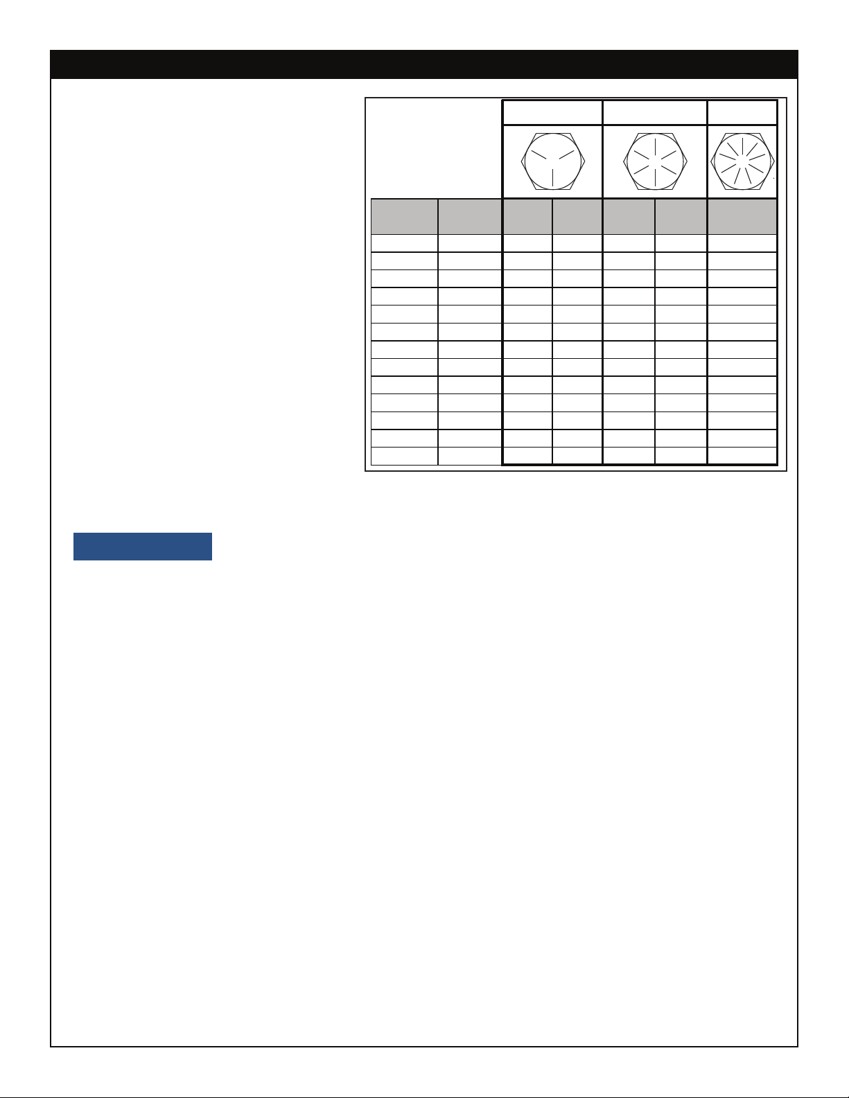
When using the torque data in the
chart, the following rules should be
observed:
• Bolt manufacturer’s particular
specifications should be consulted
when provided.
• Flat washers of equal strength
must be used.
• All torque measurements are
given in foot-pounds. To convert
to inch-pounds, multiply by 12.
• Torque values specified are for
bolts with residual oils or no special
lubricants applied.
• Torque values for socket-head
capscrews are the same as for
Grade 8 capscrews.
• Do not use these values if a different torque value or tightening
procedure is given for a specific application. Torque values listed are for general use
only. Check tightness of fasteners periodically.
• Shear bolts are designed to fail under predetermined loads. Always replace shear bolts
with identical grade.
• Fasteners should be replaced with the same or higher grade. If higher grade fasteners
are used, these should only be tightened to the strength of the original.
• Tighten plastic insert or crimped steel-type lock nuts to approximately 110 percent of the
dry torque values shown in the chart below, applied to the nut, not to the bolt head.
Tighten toothed or serrated-type lock nuts to the full torque value. Note: “Lubricated”
means coated with a lubricant such as engine oil, or fasteners with phosphate and oil
coatings. “Dry” means plain or zinc plated without lubrication. Tighten lubricated bolts
to approximately 80% of dry bolts.
Size Bolt DIA Plain Plated Plain Plated Plated
(DIA-TPI) (Inches) (Ft-Lb) (Ft-Lb) (Ft-Lb) (Ft-Lb) (Ft-Lb)
5/16-18 0.3125 17 13 25 18 22
3/8-16 0.3750 31 23 44 33 39
7/16-14 0.4375 49 37 70 52 63
1/2-13 0.5000 75 57 105 80 96
9/16-12 0.5625 110 82 155 115 139
5/8-11 0.6250 150 115 220 160 192
3/4-10 0.7500 265 200 375 280 340
7/8-9 0.8750 395 295 605 455 549
1-8 1.000 590 445 910 680 823
1 1/8-7 1.1250 795 595 1290 965 1167
1 1/4-7 1.2500 1120 840 1815 1360 1646
1 3/8-6 1.3750 1470 1100 2380 1780 2158
1 1/2-6 1.500 1950 1460 3160 2370 2865
GRADE 5 GRADE 8 GRADE 9
Torque Data Chart
NOTICE

Stellar®TM16160 TireMan Owner’s Manual | Page 5
Hydraulic Installation
Never modify or alter any of the equipment, whether mechanical, electrical, or hydraulic,
without Stellar Industries’ approval.
Do not touch or grab any hoses that could be under pressure. Release
system pressure before attempting to make adjustments or repairs.
Do not attempt service or repair when PTO is engaged.
Disassemble and assemble hydraulic components on a clean surface.
Clean all metal parts in a nonflammable cleaning fluid. Then lubricate all components to
aid in assembly.
Hydraulic fluid expands when heated. This raises the pressure in an
unventilated tank. Release the tank pressure before removing the cap completely. Failure
to do so may cause the oil to shoot out of the tank very rapidly and cause severe burns.
Do not rely on the hydraulic fluid to support the boom or crane. If
hydraulic fluid escapes, the boom or crane can fall immediately. Make sure the ground or
blocking is supporting the boom before performing any maintenance or repair.
Contaminants in a hydraulic system affect operation and will result in
serious damage to the system components. Dirty hydraulic systems are a major cause of
component failures.
If evidence of foreign particles is found in the hydraulic system, flush the system.
When installing metal hydraulic tubes, tighten all fittings finger tight. Then , in order, tighten
the fittings at the rigid end, the adjustable end, and the mounting brackets. After tubes
are mounted, install the hoses. Connect both ends of the hose with all fittings finger tight.
Position the hose so it does not rub the machine or another hose and has a minimum of
bending and twisting. Tighten fittings in both couplings.
Due to manufacturing methods, there is a natural curvature to a hydralic hose. The hose
should be installed so any bend is with this curvature.
WARNING
WARNING
WARNING
NOTICE

Page 6 | Stellar®TM16160 TireMan Owner’s Manual
Hydraulic Pressure Settings
Main Relief 4600 psi
Pressure (psi)
Function Flow (gpm) Extend Retract
Inner 10.6 4400 2200
Outer 10.6 4400 2200
Extension 10.6 4400 4400
Rotation 10.6 2200 2200
TM Rot 6.6 2200 2200
TM Pad Rot 6.6 2500 2500
TM Clamp 6.6 4200 4200
Face Seal (A)
Stellar®PN
Hose
Size
Fitting
Size Stellar®PN
O-ring Boss (B)
#4 C2027 D1245
#6 C2028 D1246
#8 C2029 D1247
#10 32223 D1248
#12 D1244 D1249
#161”
3/4”
5/8”
1/2”
3/8”
1/4”
D1250
B
A
Face Seal/O-Ring Size Chart

Stellar®TM16160 TireMan Owner’s Manual | Page 7
Hydraulic Kit - PN 105060
PN 105060
1105061 1HOSE KIT, TM12154 V3 CONT RP (incl: 2-8)
471050 4refHOSE-HYD, 0.38 X 60
371052 2refHOSE-HYD, 0.38 X 81
271051 2refHOSE-HYD, 0.38 X 76
585509 1refHOSE-HYD, 0.38 X 248
6105064 1refHOSE-HYD, 0.38 X 153
7105348 2refHOSE-HYD, 0.38 X 153
8105347 1refHOSE-HYD, 0.38 X 95
10 105063 1VAVLE SOLND 2 POS 3 WAY SV10-34-8T-N-12DR
935111 1VALVE COMB DIV FD50-44-6T-N-44
11 D1302 2FTG 6-10 MFS-MAORB 90
12 C0338 1FTG 6-6 MFS-MAORB 90
13 0279 11FTG 6-6 MFS-MORB STRAIGHT
14 13554 2QUICK CPLR FFH04-38-SAE-F
15 13555 2QUICK CPLR FFH04-38-SAE-M
18 D1193 4FTG 6-6 MFS-MOARB 45
17 13557 1QUICK CPLR FFH06-12SAE-M
16 13556 1QUICK CPLR FFH06-12SAE-F
19 C2248 1FTG 6-6 MFS-FFSS 90
20 12171 2FTG 6-6 MFS-MFS SWIVEL STRAIGHT
21 33743 1FTG 6-6 FFSS-MORB STRAIGHT
22 53479 4LOOM 1.00 SPIRAL WRAP POLYETHYLENE
24 D0107 1FTG 6-6-6 MFS-MFS-FFSS BRANCH TEE
23 C1111 4FTG 10-6 MORB-FORB STRAIGHT REDUCER
25 C1854 2FTG 6-8 MFS-MORB STRAIGHT
26 C2345 1FTG 6-6-6 MFS-MFS-MAORB TEE
ITEM PART No
.Q
TY.DESCRIPTION

Page 8 | Stellar®TM16160 TireMan Owner’s Manual
TM16160 Breakdown - PN 109359
42
23
50
29
28
7
31
10
13
35
12
8
36
29
31
22
20
CYLINDER BUSHINGS 0635
34
37
9
30
21
14
25
3
30
1
26
41
6
33
48
48 16
17
24
18
19
29
25
29
43
25
37
44
25
26
24
24
45
25
29
37
25
27
29
25
14
37
4
29
28
40
LINK WITH HOSE CLAMP
19
BLOCK 3" FROM END OF LINK
5
39
15
TOWARDS THE TM ARM.
27
38
27
2
32
BUSHINGS INCLUDED IN 67862
GEARBOX REPLACEMENT KIT 39969
26
27
TO THE OUTSIDE. CLAMP
46
47
27
31
11
C-BALANCE VALVE C6184
CYLINDER SEAL KIT 35648
41
49
VALVES SHOWN FOR REFERENCE
ROUTE HARNESS WITH HOSE THRU SPIRAL WRAP

Stellar®TM16160 TireMan Owner’s Manual | Page 9
TM16160 Bill - PN 109359
.YTQNOITPIRCSEDTRAPMETI
22V06161MTDAP012071
13V06161MTYDOB2639012
2EDISNI2V06161MTKNIL901763
22V06161MTMRA648764
569742 BEARING SWING DRIVE 14 IN ENCLOSED
KINEMATICS 2
622275 MOTOR HYD EATON 101-3454 2
252.81X05.4REDNILYC268767
822258 TURNTABLE BEARING 450-05110-
11
12V06161MTESAB044869
10 22268GEAR GUARD TM14160B PC BLAC
K1
11 22272GUARD TTB TM14160B PC BLAC
K1
11-02100-510XOBRAEG735621
13 5311 MOTOR HYD ROSS MG140611AAAB 1
14 15625CRPIN TEAR DROP 2.50X18.38 ZC 8
15 78431LIGHT FLOOD LED 3.2X2.9 850LM 16W 10-30V 2
16 C2239 FTG 2-2 MP-FP STREET ELBOW 90 2
17 C2250 FTG 2-2X1.50 MP-MP NIPPLE STRAIGHT BLK 2
231.0EPIPRLPCGTF6522C81
4THGIARTSTPN8/1KREZ2951c91
20 15770PIN TEAR DROP 3.00X10.38 SS 1
21 22273TEAR DROP PIN 3.00X16.63 SS 2
12V06161MTKNIL9342722
23 54319BUSHING COMPOSITE 2.50X1.50 32
24 2227 BUSHING BPC48DXR48 3.00X3.00 4
25 D0790WASHER 0.50 SAE FLAT YELLOW GR8 21
26 17150WASHER 0.75 SAE FLAT YELLOW GR9 50
81TALFSSU13.0REHSAW343072
28 C5902 WASHER 0.63 SAE FLAT YELLOW GR8 84
29 10172CAP SCR 0.50-13X1.00 HHGR8 21
30 17149CAP SCR 0.75-10X4.50 HHGR9 46
31 0420 CAP SCR 0.31-18X0.75 HHGR5 12
32 D1312CAP SCR 0.63-11X3.50 HHGR8 48
33 72435CAP SCR 0.63-11X5.00 HHGR8 RED PATCH36
34 C0929 CAP SCR 0.31-18X2.75 HHGR5 4
2HS52.1X31-05.0RCSPAC7031D53
4HS05.3X01-57.0RCSPAC8921163
1152.X05.3X65.0PACNIP773873
38 101592PLATE COVER BODY TM12154 V4 1
2EDISTUO2V06161MTKNIL6342793
21REBBUR00.1PMALC326704
02TALFSSU52.0REHSAW043014
42 0478 CAP SCR 0.25-20X0.50 HHGR5 12
4HSMM04XMM21RCSPAC4842634
44 70964CLAMP 3 HOSE 0.38 HYD 2800
04
2GED09TPN8/1KREZ7951C54
NOT SHOWN:
1 - 105060 - HYD KIT TM12154 V4 CONT ROT PADS
1 - 21409 - WIRE HARNESS FLOOD LIGHT TM14160
1 - 106349 - WIRE HRNS EXT 7FT 2P WP TO DT
1 - 37845 - DECAL KIT TM16160
1 - D0240 - FTG 4-2 CPRSN-MP 90
0.67FT - D1810 - TBE AIR SAEJ844 TYPE A .25 (RM)
1 - D1345 - FTG 4-2 CPRSN-MP STRAIGHT
1 - 22161 - FTG 2-2 FP-FP COUPLER STRAIGHT BRASS
1 - 56589 - ZERK 1/8 NPT STRAIGHT LONG THREAD
2 - 9752 - CONNECT 2 PIN SHROUD PACKARD
4 - 9756 - CONTACT M TERM SHROUD 18-20
4 - 8384 - CABLE SEAL 18-20 PACKARD1 - 39000
1 - 90384 - MANUAL TM16160
46 0481CAP SCR 0.25-20X2.00 HHGR5 4
4COLYN5RGHH02-52.0TUN333074
48 21151GASKET MOTOR 008-10056-
13
49 105063 VALVE SOLND 2 POS 3 WAY SV10-34-6T-N-
12DR1
50 35111VALVE COMB DIV FD50-44-6T-N-4
41

Page 10 | Stellar®TM16160 TireMan Owner’s Manual
Decal Placement - PN 37845
2
2
04 22618 DECAL- GREASE WEEKLY
DESCRIPTION
PART No.ITEM
05 37847
DECAL - STELLAR LOGO 6.00X16.5052681
DECAL- RATED LOAD
QTY
2
DECAL- TM 16160 IDENTIFICATION
DECAL- ROATATION BEARING
01 54854
03 22617
02
2
1
06
38976 DECAL- RATED LOAD 2
PN 37845
Rev Level: D
Date:
Change: Removed PN 54589.
Updated artwork to reflect
engineering changes.
Last Revision
MAXIMUM RATEDLOAD
16500 LBS
EXCEEDINGMAXIMUM RATED LOAD WILL
DAMAGEEQUIPMENT AND VOID WARRANTY
37847
7484 KG
MAXIMUM RATEDLOAD
16500 LBS
EXCEEDINGMAXIMUM RATED LOAD WILL
DAMAGEEQUIPMENT AND VOID WARRANTY
37847
7484 KG
Grease Weekly
22618
Greasebearing with EP2
(ExtremePressure Grease)
whilerotating the bearing.
1.)Lubricate bearing and pinion teeth with Molub-Alloy 936SF.
2.)Lubricate inner race and pin with EP2 (extreme pressure grease).
3.)Check gearbox oil level monthly (Traxon80W-90).
4.)Visually inspect bolts for tightness. Check torque if necessary.
Boltsoninner and outer race should be torqued to 340 ft-lbs.
Inspect Rotation Bearing Monthly
22617
STELLAR TM16160 38976
CAPACITY
CHART
15’(4.57m)
16500lbs(7484kg)
ROTATION
17’(5.18m)
14000lbs(6350kg)
20’(6.10m)
12000lbs(5443kg)


Subject to Change without Notification.
© 2020 Stellar Industries, Inc.
Other manuals for TireMan 16160
1
Table of contents
Other stellar labs Service Equipment manuals