IGD TOCSIN 30 Series Installation guide

TOC-30A-ANN TOC-30A-AN1
TOC-30A-AN2 TOC-30A-AN3
TOCSIN 30 SERIES
ANNUNCIATORS
O p e r a t i o n a n d M a n t e n a n c e
V 1 . 0 2
OLIVER I G D
CO
H S
2CO2
SO2
NO NO2
CH4
International Gas Detectors Pepper Road
Bramhall Technology Park
Stockport
SK7 5BW
England
Tel: +44 (0)161 483 1415
Fax: +44 (0) 161 484 2345
Email: [email protected]
Website: www.internationalgasdetectors.co.uk 023827

International Gas Detectors
TOC 30 Series Annunciators add extra flexibility to addressable gas detection systems, combining a colour
alarm display with E-Stops, Key Switches or other inputs.
Displayed messages are programmable as:
Safe Message: Green Background: Display When not in Alarm
Alarm Message: Flashing Red Background: Address 42xx
Displayed When Address is activated by control panel
Built in Relay &: Activated When Address is activated by control panel
Sounder
There are three digital inputs which are used by the control panel in the same manner as other addressable
inputs and have unique system addresses. Cause and Effect actions can then be programmed from the
system controller.
TOC-30 Series Annunciators can be used for door entry control.
Use the digital inputs to interface with other systems such as fire alarms .
As with detectors in the TOC-30 series the annunciators will interface with any IGD addressable control panel.
TOC-30 Annunciators are standard 2 gang fitting and as such can be used with standard plaster boxes or
dado rail to neatly fit into any environment.
Who should read this manual.
This manual is intended for use by trained installers of gas detection systems who are technically competent
and have all necessary tools to undertake installation and maintenance on this type of equipment.
Failure to install and maintain the equipment properly can render the system ineffective.
You should not undertake any of the procedures in this manual if you do not have access to the correct
equipment, have not undertaken training on this or similar equipment or are not technically qualified to install
this equipment.
Calibration gases and test equipment is available from IGD.
Introduction

MOUNTING DETAILS AND DIMENSIONS
TECHNICAL
172
158
76
48
43
86
98 18
5
20mm Entries Top, Bottom & Either Side
Part Numbers & Features
Part Number
TOC-30A-ANN
TOC-30A-AN1
TOC-30A-AN2
TOC-30A-AN3
Description
Base Unit
With E-Stop
With Key Switch
With Key Switch & E-Stop
1
1
1
1
1
1
1
1
Sounder Display E-Stop Key Switch
Housing
Sealing
Environment
Temperature
Voltage
Communication
Relay
Digital Output
Digital Input
Pellistor Port
Sounder
Display
ABS,
IP65 (using suitable glanding)
0 -95% RH Non Condensing
0-55 Deg C
12-28V DC
RS485 IGD Data Highway 24V, 0V, A, B 4 Core Screened Cable
5A Non Inductive Loads 230V AC
24V DC 100mA (Typically for LED Beacon Sounders
Suitable for use with TOC-10 Link Function
Option if fitted to Interface to MK6 or MK7 Pellistors
85dB
2 x 8 Programmable LCD with RGB Backlight
Note TOC-30A-AN3 Shown
International Gas Detectors
Single Pole
Relay
Digital
Output
Pellistor
Interface
Digital
Input

SCREENSCREEN
UP DOWN
PC
P Y W
DISPLAY
SCREEN
+24V +24V
B
NC
B
V+
V+
A
COMM
A
4-20mA
4-20mA
0V
NO
0V
1 2 3 4 5
TOC-30 INPUTS/OUTPUTS
International Gas Detectors
Note when removing cover for
interface wiring, disconnect by
carefully unplugging the 10 way
ribbon cable.
DO NOT PLUG OR UNPLUG
WHEN POWERED
E-Stop Option
Switch Option
Colour LCD
20mm Cable Entries
IGD Quick Fit Gland
Option PN
Pack of 5
Optional Pellistor Port
(IGD MK6 & MK7 Sensors)
Front Panel Ribbon Cable
Programming
& Diagnostic Interface
Solid State Output
Solid State Input
PC Programming
Port, Requires
PC Running IGD
Configurator
Software
Addressable
Highway in/out
SPCO
Relay

0V DC
24V DC
~~
A1
A1
A2
A2
Example fit
protection diodes
when switching
external DC loads.
NC
COMM
NO
NC
COMM
NO
Example fit protection
supressors when
switching external AC
loads typical device
Farnell Ref 1438460
V+
4-20mA
24V DC
Beacon
Sounder
Electrical Interfaces
International Gas Detectors
Solid State Output
Relay Output
The Solid State Output Can be used
to Switch LED Beacon Sounders if
Required.
It is recommended to use IGD LED
Beacon Sounders
Part Number 5083101
When using Other Manufacturers
Devices do Not Exceed 100mA @
24V DC
The Annunciator relay output can be used as an alarm interface to external systems, run additional
audio visual alarms or directly control other devices. Typical applications could be gas solenoid
valves, boiler shut down interfaces or similar. When switching external loads it is important to
consider the nature of the load being switched. For inductive loads suitable protection from induced
back EMF must be fitted. Many modern devices conforming to the European EMC Directive may
already have devices fitted as part of their design to limit in-rush currents and back EMF. Where
these are not fitted the following two diagrams provide guidance. Failure to observe this may result in
damage to the Annunciator.
TOC-10 Unit 1 TOC-10 Unit 2
V+
4-20mA
Spare
I/O
0V
Spare
I/O
0V
Solid State Input From TOC-10 Gas Detector
The Solid State Input can be used to
interface to IGD TOC-10 Series
Flammable Gas Detectors. Wire as
Indicated and the Input Will Read the
Two Alarm Levels From the TOC-10.
This will display on an Addressable
Controller in the Same Manner as Any
Other Gas Detector.
Up to 6 TOC-10 Detectors can be Daisy
Chained to the Input

Addressing the Assembly International Gas Detectors
UP DOWN
PC
P Y W
DISPLAY
V+
4-20mA
1 2 3 4 5
In Normal Operation This LED
is Lit When 24V DC is Applied
and Will Flash to Indicate
Communication
The TOC-30 Annunciator is an Addressable Device and Comes
Equipped With a Simple Interface to Allow the Base Address to
be Set.
To Check The Set Address,
Press and Hold the Right Hand Button Labelled ‘DOWN’ For > 2s
Release Button the Light Pattern Will Now Indicate the set Address as Shown in the Table Below.
With the Set Address Lit, the UP and DOWN buttons can now be used to alter the address if required
With the Required Address lit, Press and Hold the DOWN Button Until the LED’s go out. Release the
DOWN button and the new Base Address is Now Set.
Note That the Left LED Will Now be Flashing if the Annunciator is Communicating With its Control
Panel.
4100
4108
4116
4124
4101
4109
4117
4125
4102
4110
4118
4126
4103
4111
4119
4127
4104
4112
4120
4128
4105
4113
4121
4129
4106
4114
4122
4130
4107
4115
4123
4131
Setting the base address sets the address for all other components on the annunciator as follows:
For a Base Address Set of 4101:
NOTE: WHEN SETTING ADDRESSES YOU CANNOT HAVE TWO DEVICE ADDRESSES SET THE
SAME ON THE SAME ADDRESSABLE HIGHWAY.
E-Stop Input = Base Address = 4101
4102 = key Switch
4103 = TOC-10 Digital Input
4104 = Pellistor Input
4201 = Sounder, Display, Digital Output (external Beacon Sounder)
4202 = Sounder, Display, Digital Output (external Beacon Sounder), Relay
S YS TE M S TATU S
EDIT
4119
Note when editing
the base address
the display will also
update
UP DOWN
1 2 3 4 5

Address Diagnostics
Fault Messages
International Gas Detectors
UP DOWN
PC
P Y W
DISPLAY
V+
4-20mA
1 2 3 4 5
The Unit Base Address Can be Checked by Pressing the UP
Button for More Than 2 Seconds. Now Each Button Press either
UP or Down Will Sequentially Display Each Set Address on the
Unit.
To Exit This Mode Press Either Button For More Than 2 Seconds
In the event that the annunciator detects that it cannot communicate to its host control panel then the
following alternating message will be displayed.
S YS TE M S TATU S
S YS TE M S TATU S
S YS TE M S TATU S
S YS TE M S TATU S
S YS TE M S TATU S
S YS TE M S TATU S
S YS TE M S TATU S S YS TE M S TATU S
Estop
add=4101
al2
add=4202
keysw
add=4102
j8-t10
add=4103
al1
add=4201
j5=none
add=000
Call
service
no
comms
UP
DOWN
DOWN
DOWN
DOWN
DOWN
UP
UP
UP
UP
AL1 When Set Triggers The
Internal Sounder and Display
AL2 When Set Triggers The
Internal Sounder, Display &
Relay
This Address Reads the Digital Input
From TOC-10 Detectors
If Fitted this Address is the On-Board
Flammable Gas Detector. This Port
will Run a MK6 or MK7 Flammable
Gas Detector Directly from the Unit
<>

Addressable Interface Wiring
International Gas Detectors
SCREENSCREEN
UP DOWN
PC
P Y W
DISPLAY
SCREEN
+24V +24V
B
NC
B
V+
V+
A
COMM
A
4-20mA
4-20mA
0V
NO
0V
1 2 3 4 5
SCREEN
+24V
B
A
0V
ZERO
FAULT
CAL
360
CHASS
24V DC
B
A
GND
mA
P Y W
mA+360CONC0V mA-
Control Panel
4 Core Screened Cable
Typically FP200, SY or
CY Sytle Cables.
Refer to IGD Cable Sizing
Guide For Further
Information
ZERO
FAULT
CAL
360
CHASS
24V DC
B
A
GND
mA
P Y W
mA+360CONC0V mA-
Example - Flammable Gas DetectorExample - Flammable Gas Detector
Note: It does not matter which connector is used
as either the cable in or cable out connection
Devices can be in any order on an addressable highway but it
is advisable to install in address sequence as thi swill aid
future servicing
NOTE: WHEN SETTING ADDRESSES YOU CANNOT HAVE TWO DEVICE ADDRESSES SET
THE SAME ON THE SAME ADDRESSABLE HIGHWAY.
IGD addressable systems use a 4 core cable or highway to connect all system devices. Typically an
addressable highway will support up to 32 devices as any mix of gas detectors, addressable relays,
addressable inputs. You must not have duplicate device addresses on the same highway cable. Some
Controllers support more than one highway, in this case it is allowed to have the same addresses on
different highway cables on the same controller. An addressable highway can run for up to 1000M but it
must be ensured that the cable size is large enough to keep the supply voltage over 17V DC. Use the
IGD cable sizing guide to check required cable sizes.
120 W
At the last device on the
highway it is advisable if
the cable run is over
250M to fit a 120W
resistor across the A-B
terminals. This will reduce
‘noise’ on the highway
and aid reliability. Under
250M of Cable This is Not
Required.

Typical Use International Gas Detectors
Annunciator
Base Address
4101
TOC-30A-PHC
Flammable Gas Detector
Address 4110
T10-LPG-23
Flammable Gas Detector
4 Core FP200 Cable Connected to Connector J14,
Highway 1 on Tocsin 700
2 Core Cable
In this example the Tocsin 700, solenoid
valve and T10 are mains powered. The
annunciator and TOC-30 are powered
from Tocsin 700 Highway 1
The above system has the following device addresses available for use
The following Cause and Effect Has:
First Level Alarm Activates Annunciator Display and Sounder to alert Users
Second Level Alarm Activates Annunciator Display, Sounder and Relay to Cut off the Gas Supply
Device
Annunciator E-Stop (Base Address)
Annunciator Digital Input (TOC-10)
Annunciator Sounder/Display
Annunciator Relay
TOC-30A-PHC Flammable Gas Detector
Address
4101
4103
4201
4202
4110
Channel Detector Tag/Location Type Range Alarms Output Output Detail
Number Address Levels
1
2
3
Not Available
on TOC-625
Channel Detector Tag/Location Type Range Alarms Output Output Detail
Number Address Levels
1
2
3
Not Available
on TOC-625
Channel Detector Tag/Location Type Range Alarms Output Output Detail
Number Address Levels
1
2
3
Not Available
on TOC-625
1
1
1
4101
4103
4110
ESTOP
KITCHEN
TANK
TOC-30A-AN1
T10-LPG-23
TOC-30A-PHC
NA
0-100
% LEL
0-100
% LEL
10
10
10
10
20
20
4202
4201
4202
4202
4202
4202
ESTOP CUTS OFF GAS AND
SETS ALARMS
SET LOCAL ALERT
CUT OFF GAS
SET LOCAL ALERT
CUT OFF GAS
NOT USED
NOT USED
NOT USED
This manual suits for next models
4
Other IGD Gas Detector manuals
Popular Gas Detector manuals by other brands
ZyAura
ZyAura ZG906CMONP operating instructions
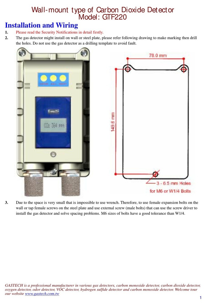
GasTech
GasTech GTF220 manual

Apollo
Apollo 51000-600 installation guide
sauermann
sauermann SGTP-CO quick start guide

Greystone Energy Systems
Greystone Energy Systems CDD Installation and operating instructions

Hydro Instruments
Hydro Instruments GA-170 Operation and maintenance manual
