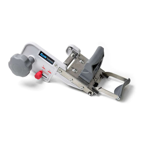
IGM 142-PD80 User manual

Distributor:
IGM nástroje a stroje s.r.o.
Ke Kopanině 560, 252 67, Tuchoměřice
Czech Republic, EU
Phone: +420 220 950 910
E-mail: [email protected]
Website: www.igmtools.com
Edgeband Trimmer for an ABS Tape
Operationg instructions
2022-07-12
142-PD80 IGM Edgeband Trimmer for an ABS Tape Manual EN v2.2.00 A4ob
142-PD80
www.igmtools.info
PDF ONLINE

-2-www.igmtools.com
Thoroughly read this manual and follow the safety instructions provided!
Technical changes and typographical errors reserved!
Dear customer,
This manual contains important information and instructions for installation and proper use of the rounding-
chamfering router PD80.
This manual is part of the machine and is therefore not advisable to store it anywhere else than in the vicinity of
the machine so you or other persons operating the machine can consult it at any time.
Please read and follow the safety instructions!
Before the first use of the machine, please read this manual. It will make your work easier and you can
simultaneously reduce the risk of any mistakes, damage to the machine or personal injury. The design,
construction, images or content may slightly differ due to continuous development. Should you discover
1. DECLARATION OF CONFORMITY
The undersigned: IGM nástroje a stroje s.r.o.
Address: Ke Kopanině 560
Tuchoměřice, Praha-západ, PSČ 252 67
Czech Republic, EU
Tel. +420 220 950 910
Certifies
Product: Edgeband Trimmer
Model: PD80
Manufacturer: CO-MATIC Machinery Co., Ltd.,No. 473-16,
San Feng Road, Houli District, Taichung
City,Taiwan, R.O.C. 42156
We declare on our sole responsibility that the product
described in this manual is in compliance with the
following Standards: EN ISO 12100, EN ISO 13857, EN
349, EN 953, EN 60204-1, EN ISO 11202,
EN 55014-1, EN 55014-2 according to the provisions
of Directives 2006/42/EC, 2004/108/EC, 2006/95/EC,
2002/95/EC.
Signed: Ivo Mlej
Manager
CONTENTS PAGE
1. DECLARATION OF CONFORMITY 2
2. WARRANTY SERVICE 3
3. SAFETY 3
3.1 Instructions 3
3.2 General safety instructions 3
3.3 Risks 4
4. TECHNICAL SPECIFICATION 4
4.1 Machine Description 4
4.2 Technical parameters 4
4.3 Supplied with 4
5. TRANSPORT, UNPACKING AND ASSEMBLY 4
5.1 Transport and Unpacking 4
5.2 Assembly (compilation) 4
5.3 Connection to power
5
5.4 Dust extraction 5
6. PREPARATION FOR OPERATION 5
6.1 Assembly of the Trimmer 5
6.2 Adjusting the bearing stop 6
6.3 Calibrating the trimming depth
6
7. OPERATION 6
7.1 Trimming of wide tape on the edge
6
7.2 Trimming a radius on the edge 6
7.3 Finishing an edge with a Radius Scraper
7
7.4 Trimming with a chamfer bit 7
8. MAINTENANCE AND CONTROL 7
8.1 Maintenance after work 7
9. MALFUNCTION ASSISTANCE 7
10. ENVIRONMENTAL PROTECTION 7
11. OPTIONAL ACCESSORIES 7
Operating instructions EN

-3-www.igmtools.com
2. WARRANTY SERVICE
Warranty is governed by the Terms and Conditions and
Warranty conditions of the company IGM
tools and machines Ltd. The version of which is
available at www.igmtools.com.
3. SAFETY
3.1 Instructions
This machine is intended for work with wood and
wooden materials.
To use the machine properly, adhere to the rules of
operation and maintenance, described in this manual.
The machine can only be operated by individuals who
are familiar with its operation and maintenance and
are aware of potential risks.
Comply with the minimum age requirement set out by
law.
The machine can only be used in perfect technical
condition.
All security and safety features must be installed, when
in use.
Besides the operating manual, make sure to also follow
the safety guidelines and specific regulations set out
by your country and generally recognized technical
rules regarding operation of woodworking power
tools.
The manufacturer or the supplier will not be held
responsible in case of improper use.
Risks are borne by users.
Should any of these points occur, warranty claims
cannot be applied:
- Unsuitable working environment: high humidity,
squalor.
- Damage caused by improper installation of the tool
or incorrect storage.
- Using a malfunctioning machine.
- Failure to comply with the manual: transport, storage,
installation, operation, cleaning and maintenance of
the power tool.
- Using unauthorized spare parts.
- Unauthorized assembly of the machine.
- Never use worn parts.
3.2 General safety instructions
Power tool may be dangerous when mishandled
Thoroughly read the operating manual and make sure
you understand everything before you start any work
on the power tool.
Protect this power tool from dirt and moisture and
when selling the power tool make sure to hand it to the
new owner.
Any changes or rebuilding of the machine is not
allowed.
Daily, before starting work, make sure the machine and
its protection features are functioning. Replace any
identified insufficiencies or faulty safety features.
Turn on the power tool only if it is in perfect technical
condition.
Protect long hair with a hat or a hairnet.
Wear tight-fitting clothing and put aside any bracelets,
rings, necklaces or a tie. Wear work shoes only. Do not
wear casual shoes or sandals in any case.
Follow the personal protection regulations.
Always wear safety goggles. Always use hearing
protection. Make sure you have enough work space.
Do not perform any operations for which this machine
is not intended for.
Secure proper lighting. Make sure that the power cord
is not in the way of your work.
Keep the work area clean. Never touch the power tool’s
moving parts when working.
Be attentive and concentrated. Work with reason. Never
work under the influence of intoxicating agents, such
as alcohol or drugs.
Be attentive to the movement of children around a
running machine. Never leave the machine running
without supervision. When leaving your workspace,
always turn the power tool off. Only an electrician may
repair damaged electrical connections. Immediately
replace a damaged cable.
Before connecting to power, make sure the switch is in
the‘OFF’ position (turned off).
Do not use the machine if the switch ON-OFF is
malfunctioning.
Using other accessories than those recommended in
this manual can be dangerous.
Make sure the cable is long enough, is not too tense or
does not fold over an edge.
Operating instructions EN

-4-www.igmtools.com
Operating instructions EN
3.3 Risks
Even when using the trimmer according to the
manual, there is still some danger.
Danger of a rotating tool. Watch out for cloths or hair
getting stuck.
The tool is sharp, watch out so you do not cut yourself.
Use gloves.
Danger of flying particles. Wear eye protection and a
respirator.
4. TECHNICAL SPECIFICATION
4.1 Machine Description
1Main Switch
2 Machine Housing
3 Motor
4 Calibration
5 Quick Release
6 Dust Extraction Outlet
7 Safety Cover
8 Router Bit/Cutter
9Bottom Cover
10 Radius Scraper
g. 1
4.2 Technical parameters
Power 450W / 230V
Speed 30 000/rpm.
Router Height setting 16mm
Collet 6mm
Weight 2kg
4.3 Supplied with
Edgeband Trimmer
Plastic Case
Wrenches 13 and 22 mm
Collet 6mm
Radius Scraper
Router Bit R2 mm, S6 mm
5.TRANSPORT, UNPACKING AND ASSEMBLY
5.1 Transport and Unpacking
Make sure there is no apparent damage caused by
transport, which could have caused damage to the
machine or your health.
5.2 Assembly (compilation)
The machine is supplied assembled. Should you
discover any defects while unpacking, contact your
supplier and do not use it.

-5-www.igmtools.com
Operating instructions EN
5.3 Connection to power
Before connecting the machine to electricity network,
make sure that the main switch is in the‘0’ OFF (turned
off) position.
The plug, as well as the cable must meet standards.
Line voltage must be consistent with the label on the
power tool. Wiring and repairs of electrical parts may
be carried out only by a qualified electrician.
5.4 Dust Extraction
The trimmer has to be connected to an industrial dust
extractor before use. To connect, use the extraction
outlet (Note 6) Use a 25,4mm diameter hose. Some
shavings may be charged with static electricity and
remain“stuck” to material or power tool.
We recommend using a 2,5m3/s suction power.
Turn on the exhaustion before starting the machine
6. PREPARATION FOR OPERATION
Before operation, make sure the workpiece is firmly
stationed.
Connect the dust extraction to the outlet.
Check if the rotation of the power tool does not
exceed the limit of the router bit.
6.1 Assembly of the Trimmer
First separate the motor and the trimmer. Completely
unscrew the quick release lever and remove it. Now,
by pulling down you can remove the motor from the
trimmer.
g. 2
Select the adequate tool for trimming. Use 22mm and
13mm wrenches to release the hex nut (fig.3). Based
on the selected router/cutter, choose a suitable collet
(6mm or 8mm). Make sure the collet and router bit are
clean and are not damaged. Now affix it to the power
tool (fig.4). Make sure the router bit is correctly placed
into the collet and is sufficiently pushed in according to
the mark on the arbor. Improper assembly may cause
danger in the form of vibration, or tool release. Do not
tighten the union bit, if the router bit is not inserted,
you will prevent damage to the collet. Use 22mm and
13mm wrenches to tighten the hex nut and make sure
it is thoroughly affixed (fig.5).
g. 3 g. 4
g. 5 g. 6
When the bit is installed, re-insert the support table
onto the motor in the arrow direction (fig.6). Put back
the quick release lever and tighten the nut. Adjust
the height of the supporting table on the body of the
motor (fig.7). Tighten the quick release lever in the
arrow direction (fig.8). to lock it. The supplied R2 radius
router bit is ideal for a 2mm edge. The router bit radius
should match the thickness of the edge.
1.
2.
3.
g. 7 g. 8

-6-www.igmtools.com
Operating instructions EN
6.2 Adjusting the bearing stop
Push the pin upwards and rotate it in the arrow
direction (g.9 and g.10). Once the pin is pushed
into the plastic housing, it does not fulll its function
as a stop for the bit’s bearing. When the pin is
lowered back, it rests on the bearing. After starting
the trimmer, the bearing will not spin together with
the machine. This way, you will prevent burning of
the workpiece with the spinning bearing.
g. 9 g. 10
g. 11
6.3 Calibrating the trimming depth
The supporting table sleeve can be rotated in
both directions to achieve the desired trimming
depth (g.12). One notch around the perimeter is
0,05mm. When rotated by 360° it shifts by 2mm
(on notch on the vertical scale). Set the depth, so
that the edge is beyond the workpiece by tenths of
a millimeter. You can later align this discrepancy
with the radius scraper. This overlap secures that
the router does not damage your workpiece.
g. 12
7. OPERATION
Turn the trimmer on by placing the switch in the ON
“1” position. Hold it rmly with both hands by the
handles. Move the trimmer along the board to trim
edges. To turn it o, by placing the switch into an
OFF “0” position.
7.1 Trimming of wide tape on the edge
To trim a wider excess ABS edge (overlap more than
3mm) place the trimmer horizontally (g.18 and 19.)
g. 18 g. 19
7.2 Trimming a radius on the edge
To square up a banded edge, ax a router bit into
the trimmer. Move the trimmer into operational
position, align the trimmer with the material to
allow for a smooth drive into the material. Lead the
router bit with the help of a supporting table along
the workpiece as depicted in the red highlighted
area (g.16). Now you can start trimming the edge
(g.17)
g. 16
g. 17

-7-www.igmtools.com
Operating instructions EN
7.3 Finishing an edge with a Radius Scraper
For nishing an edge – cut o the excess edge
after trimming. Pull out the Radius Scraper by
tipping and then pulling it out (g.13) and (g.14).
Grab the scraper with both hands for better support
when trimming edges (g.15).
9. MALFUNCTION ASSISTANCE
The Motor does not start
* There is no power – check power supply and fuse
* Motor, switch, cable failure – contact the supplier
* Worn carbon brushes – see carbon brush
replacement
Excessive vibrations
*Router bit is badly axed – Reax it again
The cut is not clean
*Blunt instrument – use a sharper bit
10. ENVIRONMENTAL PROTECTION
Protect the environment. Your device contains
recyclable materials. Please leave it to specialized
institutions.
11. OPTIONAL ACCESSSORIES
Collet 8mm
code: 142-PD80-080
IGM End trimmer for shaped and straight panels
code: M951
IGM Vacuum Clamp One-sided
code: M964
g. 13 g. 14
g. 15
7.4 Trimming with a chamfer bit
The radial router bit can be exchanged for a chamfer
bit. Set the depth of trimming according to previous
steps. – maximum depth 2mm and maximum stroke 6
mm.
8. MAINTENANCE AND CONTROL
Before attempting to inspect or maintain the
trimer, always make sure it is turned o and
unplugged
8.1 Maintenance after work
After work, clean the machine from impurities.
Especially make sure that the motor vents are not
clogged up. To unplug the vents, use a brush with
soft bristles or compressed air.
Carbon brush replacement
If the machine excessively sparkles and is losing
performance a carbon brush replacement is needed.
To maintain SAFETY and RELIABILITY of the product,
all repairs and any other maintenance must be carried
out by an authorized IGM service center and with the
use of original spare parts.

Operating instructions EN
IGM Worktable for edgebander and trimmer for
DR500-BR300
code: 142-ST95A
IGM Straightline edgebanding and trimming kit for
worktable
code: 142-ST97
IGM nástroje a stroje s.r.o., Ke kopanině 560,
Tuchoměřice, 252 67, Czech Republic, E.U.
+420 220 950 910,www.igmtools.com
© 2022 IGM nástroje a stroje s.r.o.
Other manuals for 142-PD80
1
This manual suits for next models
1
Table of contents
Other IGM Trimmer manuals
