Ignite B64800101 Manual

7495823enUS (A)
November 2022
Printed in USA
Original Instructions
© 2022 Ignite Attachments.
All Rights Reserved.
Operation & Maintenance Manual
Three-Point Tine Rake
Three-Point Tine Rake 60 S/N: B64800101 & Above
Three-Point Tine Rake 72 S/N: B64900101 & Above
Three-Point Tine Rake 84 S/N: B64A00101 & Above


1
FOREWORD............................................................................................................................................................3
SERIAL NUMBER LOCATION ...........................................................................................................................3
IMPLEMENT IDENTIFICATION ..........................................................................................................................3
Front Of Implement ........................................................................................................................................3
Rear Of Implement.........................................................................................................................................3
FEATURES AND ACCESSORIES ......................................................................................................................4
Standard Items..............................................................................................................................................4
SAFETY AND TRAINING RESOURCES....................................................................................................................5
SAFETY INSTRUCTIONS..................................................................................................................................5
Safe Operation Is The Operator’s Responsibility (Implement) ..................................................................................5
Safe Operation Needs A Qualified Operator......................................................................................................... 5
Use Safety Rules ...........................................................................................................................................5
Call Before You Dig ........................................................................................................................................5
Silica Dust Exposure.......................................................................................................................................6
FIRE PREVENTION...........................................................................................................................................6
Maintenance.................................................................................................................................................6
Operation.....................................................................................................................................................6
Electrical......................................................................................................................................................6
Hydraulic System...........................................................................................................................................6
Fueling ........................................................................................................................................................7
Starting........................................................................................................................................................7
Spark Arrester Exhaust System......................................................................................................................... 7
Welding And Grinding .....................................................................................................................................7
Fire Extinguishers ..........................................................................................................................................7
PUBLICATIONS AND TRAINING RESOURCES .................................................................................................8
IMPLEMENT SIGNS (DECALS) .........................................................................................................................8
OPERATING INSTRUCTIONS ................................................................................................................................ 10
DAILY INSPECTION........................................................................................................................................ 10
Implement Mounting Frame............................................................................................................................ 10
Three-Point Hitch......................................................................................................................................... 10
OPERATING PROCEDURE WITH COMPACT TRACTORS ............................................................................... 11
Approved Compact Tractor Models & Requirements............................................................................................ 11
Compact Tractor / Implement Setup ................................................................................................................. 11
Entering And Exiting The Compact Tractor ........................................................................................................ 11
Installing The Three-Point Implement ............................................................................................................... 11
Control Functions Three-Point Hitch (Implement) ................................................................................................ 14
Driving The Implement And Tractor To Worksite.................................................................................................. 14
Angled Positioning ....................................................................................................................................... 15
Backfilling Positioning ................................................................................................................................... 16
Operating The Three-Point Implement .............................................................................................................. 16
Removing The Three-Point Implement.............................................................................................................. 16
LIFTING THE IMPLEMENT.............................................................................................................................. 19
TRANSPORTING THE IMPLEMENT ON A TRAILER ........................................................................................ 19
Fastening The Implement To A Trailer............................................................................................................... 19
TRANSPORTING THE IMPLEMENT AND MACHINE ON A TRAILER................................................................ 20
PREVENTIVE MAINTENANCE............................................................................................................................... 22
MAINTENANCE SAFETY WARNINGS ............................................................................................................. 22
TROUBLESHOOTING CHART ........................................................................................................................ 23
TABLE OF CONTENTS

2
MAINTENANCE INTERVALS........................................................................................................................... 24
LUBRICATION LOCATIONS............................................................................................................................ 24
REMOVING AND INSTALLING PIVOT MOUNT ................................................................................................ 25
REMOVING AND INSTALLING RAKE TINES ................................................................................................... 27
STORAGE AND RETURN TO SERVICE........................................................................................................... 28
Implement Storage....................................................................................................................................... 28
Return To Service ........................................................................................................................................ 28
SPECIFICATIONS.................................................................................................................................................. 29
TINE RAKE DIMENSIONS ............................................................................................................................... 29
PERFORMANCE SPECIFICATIONS ................................................................................................................ 31
TORQUE SPECIFICATION FOR BOLTS .......................................................................................................... 32
Torque For General SAE Bolts ........................................................................................................................ 32
Torque For General Metric Bolts...................................................................................................................... 33
WARRANTY .......................................................................................................................................................... 35
IMPLEMENT WARRANTY ............................................................................................................................... 35
TABLE OF CONTENTS

3
SERIAL NUMBER LOCATION
Figure 1
P142017b
Always use the serial number (Item 1) [Figure 1] of the
three-point tine rake when requesting service information
or when ordering parts. Earlier or later models
(identification made by serial number) may use different
parts, or it may be necessary to use a different procedure
in doing a specific service operation.
IMPLEMENT IDENTIFICATION
Front Of Implement
Figure 2
P-96311a
REF. DESCRIPTION
1 Locking Pin
2 Storage Stand
3 Rake Tine
4 Pivot Assembly
Rear Of Implement
Figure 3
P-96312a
FOREWORD

4
REF. DESCRIPTION
1 Three-Point Hitch (Category 1)
2 Mainframe
3 Tine Rake Frame
FEATURES AND ACCESSORIES
Standard Items
The three-point tine rake is equipped with the following
standard items
• Five Forward Angles.
• Five Rear Angles.
• Rear Three-Point Quick Hitch Compatible.
• Equipped With Storage Stand.
FOREWORD
5
SAFETY INSTRUCTIONS
Safe Operation Is The Operator’s
Responsibility (Implement)
Safety Alert Symbol
This symbol with a warning statement means:
“Warning, be alert! Your safety is involved!” Carefully
read the message that follows.
DANGER
The signal word DANGER on machine signs and in
the manuals indicates a hazardous situation which, if
not avoided, will result in serious injury or death.◂
D-1002
WARNING
The signal word WARNING on the machine and in the
manuals indicates a potentially hazardous situation
which, if not avoided, could result in serious injury or
death.◂
W-2044
IMPORTANT
This notice identifies procedures which must be
followed to avoid damage to the machine.◂
I-2019
The machine and implement must be in good operating
condition before use.
Check all of the items on the Service Schedule decal (if
equipped) in the Every 10 Hours section or as shown in
the Operation & Maintenance Manual.
Safe Operation Needs A Qualified Operator
For an operator to be qualified, he or she must not use
drugs or alcoholic drinks which impair alertness or
coordination while working. An operator who is taking
prescription drugs must get medical advice to determine
if he or she can safely operate a machine.
Use Safety Rules
• Read and follow instructions in the machine and the
implement’s Operation & Maintenance Manual
before operating.
• Check for underground lines before operating
implement (if applicable).
• In addition to the design and configuration of
equipment, hazard control, and accident prevention
are dependent upon the awareness, concern,
prudence, and proper training of personnel involved
in the operation, transport, maintenance, and
storage of equipment.
• Check that the implement is securely fastened to the
machine.
• Make sure all the machine controls are in the neutral
position before starting the machine.
• Operate the implement only from the operator’s
position.
• Operate the implement according to the Operation &
Maintenance Manual.
• When learning to operate the implement, do it at a
slow rate in an area clear of bystanders.
• DO NOT permit personnel to be in the work area
when operating the machine and implement.
• The implement must be used ONLY on approved
machines. Visit igniteattachments.com for an
updated list of approved implements for each
machine model.
• DO NOT modify equipment or add implements that
are not approved by the manufacturer.
• DO NOT make any adjustments or repairs on the
machine or implement while the engine is running.
• Keep shields and guards in place. Replace if
damaged.
Call Before You Dig
P200081
Dial 811 (USA Only)
Dial 1-888-258-0808 (USA & Canada)
When you call, you will be directed to a location in your
state / province / city for information about buried lines
(telephone, cable TV, water, sewer, gas, etc.).
SAFETY AND TRAINING RESOURCES

6
Silica Dust Exposure
NA3504
Silica dust can cause lung disease and is known to the
state of California to cause cancer.
Cutting or drilling concrete containing sand or rock
containing quartz may result in exposure to silica dust.
Do not exceed Permissible Exposure Limits (PEL) to
silica dust as determined by OSHA or other job site Rules
and Regulations. Use a respirator, water spray, or other
means to control dust.
FIRE PREVENTION
NA3505
Maintenance
The machine and some attachments have components
that are at high temperatures under normal operating
conditions. The primary source of high temperatures is
the engine and exhaust system. The electrical system, if
damaged or incorrectly maintained, can be a source of
arcs or sparks.
Flammable debris (leaves, straw, etc.) must be removed
regularly. If flammable debris is allowed to accumulate, it
can cause a fire hazard. Clean often to avoid this
accumulation. Flammable debris in the engine
compartment is a potential fire hazard.
The operator’s area, engine compartment, and engine
cooling system must be inspected every day and cleaned
if necessary to prevent fire hazards and overheating.
All fuels, most lubricants, and some coolants mixtures are
flammable. Flammable fluids that are leaking or spilled
onto hot surfaces or onto electrical components can
cause a fire.
Operation
Do not use the machine where exhaust, arcs, sparks, or
hot components can contact flammable material,
explosive dust, or gases.
Electrical
P200082
Check all electrical wiring and connections for damage.
Keep the battery terminals clean and tight. Repair or
replace any damaged part or wires that are loose or
frayed.
Battery gas can explode and cause serious injury. Use
the procedure in the Operation & Maintenance Manual for
connecting the battery and for jump starting. Do not jump
start or charge a frozen or damaged battery. Keep any
open flames or sparks away from batteries. Do not
smoke in battery charging area.
Hydraulic System
Check hydraulic tubes, hoses and fittings for damage and
leakage. Never use open flame or bare skin to check for
SAFETY AND TRAINING RESOURCES

7
leaks. Hydraulic tubes and hoses must be properly routed
and have adequate support and secure clamps. Tighten
or replace any parts that show leakage.
Always clean fluid spills. Do not use gasoline or diesel
fuel for cleaning parts. Use commercial nonflammable
solvents.
Fueling
P200084
Stop the engine and let it cool before adding fuel. No
smoking! Do not refuel a machine near open flames or
sparks. Fill the fuel tank outdoors.
Ultra Low Sulfur Diesel (ULSD) poses a greater static
ignition hazard than earlier diesel formulations with
higher sulfur content. Avoid death or serious injury from
fire or explosion. Consult with your fuel or fuel system
supplier to ensure the delivery system is in compliance
with fueling standards for proper grounding and bonding
practices.
Starting
Do not use ether or starting fluids on any engine that has
glow plugs or an air intake heater. These starting aids
can cause explosion and injure you or bystanders.
Use the procedure in the Operation & Maintenance
Manual for connecting the battery and for jump starting.
Spark Arrester Exhaust System
The spark arrester exhaust system is designed to control
the emission of hot particles from the engine and exhaust
system, but the muffler and the exhaust gases are still
hot.
Check the spark arrester exhaust system regularly to
make sure it is maintained and working properly. Use the
procedure in the Operation & Maintenance Manual for
cleaning the spark arrester muffler (if equipped).
Welding And Grinding
Always clean the machine and implement, disconnect the
battery, and disconnect the wiring from the Ignite
Attachments controllers before welding. Cover rubber
hoses, battery, and all other flammable parts. Keep a fire
extinguisher near the machine when welding.
Have good ventilation when grinding or welding painted
parts. Wear a dust mask when grinding painted parts.
Toxic dust or gas can be produced.
Dust generated from repairing nonmetallic parts such as
hoods, fenders, or covers can be flammable or explosive.
Repair such components in a well-ventilated area away
from open flames or sparks.
Fire Extinguishers
P200083
Know where fire extinguishers and first aid kits are
located and how to use them. Inspect the fire
extinguisher and service the fire extinguisher regularly.
Obey the recommendations on the instructions plate.
SAFETY AND TRAINING RESOURCES
8
PUBLICATIONS AND TRAINING
RESOURCES
The following publications are also available for your
Ignite Attachments implement. Access them online at
igniteattachments.com.
C217655
Operation & Maintenance
Manual
Complete instructions on
the correct operation and
the routine maintenance
of your implement.
7495823.
For the latest information on Ignite Attachments products
and the Ignite Attachments Company, visit our website at
igniteattachments.com.
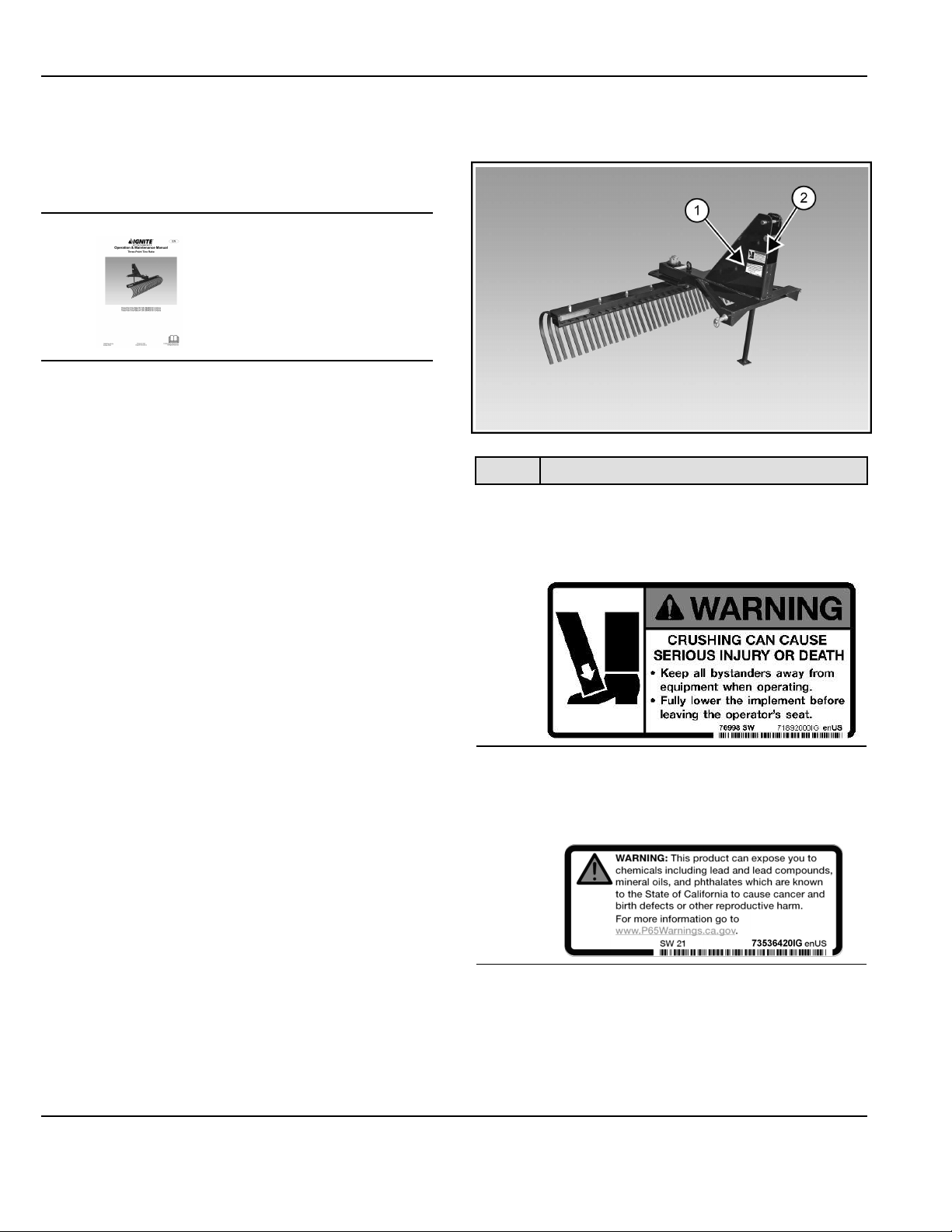
IMPLEMENT SIGNS (DECALS)
Figure 4
P-96311b
REF. DECAL
1 Crush Warning
Located near 3 point hitch, both sides
71892000IG
2 Prop 65
Located near 3 point hitch
73536420IG
SAFETY AND TRAINING RESOURCES


10
DAILY INSPECTION
Implement Mounting Frame
Figure 6
P-96311c
• Inspect the lower implement mounts (Item 1) and
upper mount (Item 2) [Figure 6] and all welds on the
implement for wear and damage each time the
implement is removed from the machine.
• Check the following items at the start of a work day:
▷Check for damaged or missing decals. Replace if
necessary.
▷Replace any worn or damaged parts immediately.
• Frequently inspect the implement to ensure that all
components are secure and that all bolts and nuts
are thoroughly tightened.
Three-Point Hitch
See your machine Operation & Maintenance Manual for
detailed information on inspecting three-point hitch.
WARNING
UNINTENDED MOVEMENT HAZARD
Failure to follow instructions can cause serious
injury or death.
The parking brake must be engaged before leaving
the operator’s seat. Rollaway can occur because the
transmission may not prevent machine movement.
Lock the brake pedals together (if equipped) before
activating the parking brake.◂
W-2656
Figure 7
P138256
• Inspect the three-point hitch linkage, PTO shaft
splines, guards, and shields. Replace if damaged or
missing [Figure 7]. Repair broken or loose parts.
OPERATING INSTRUCTIONS
11
OPERATING PROCEDURE WITH COMPACT
TRACTORS
Approved Compact Tractor Models &
Requirements
Rake 60” Rake 72” Rake 84”
Tractor HP 18–60 HP 18–60 HP 26–60 HP
The chart shows the approved box blade models for
compact tractors based on horsepower.
Warranty on this implement is void if used on a
nonapproved carrier. Contact your Ignite Attachments
representative for a current list of compatible carriers.
Compact Tractor / Implement Setup
Setting Up The Ballast
Install the correct ballast on the compact tractor before
installing the implement. See the compact tractor
Operation & Maintenance Manual for ballast information.
Entering And Exiting The Compact Tractor
WARNING
INSTABILITY HAZARD
Failure to obey warnings can cause the machine to
rollover.
• Use Roll-Over Protective Structure (ROPS) and
fasten the seat belt.
• Install the correct rear ballast.
• Do NOT exceed the Loader lift capacity.
• Check tire condition and proper air pressure.
• Use tires with the correct load rating.◂
W-3043
See your compact tractor Operation & Maintenance
Manual for detailed instructions on entering and exiting
the machine.
Installing The Three-Point Implement
NOTE: Your machine and attachment and / or implement
models may vary, but the procedure is the same.
Always inspect the compact tractor three-point
hitch and implement three-point mounting before
installation. (See Daily Inspection on Page 10) .
WARNING
GENERAL HAZARD
Failure to obey warnings can cause serious injury or
death.
Obey all warnings on the machine and in the
manuals.◂
W-2744
NOTE: The following images may not show your exact
three-point implement but the procedure is the
same.
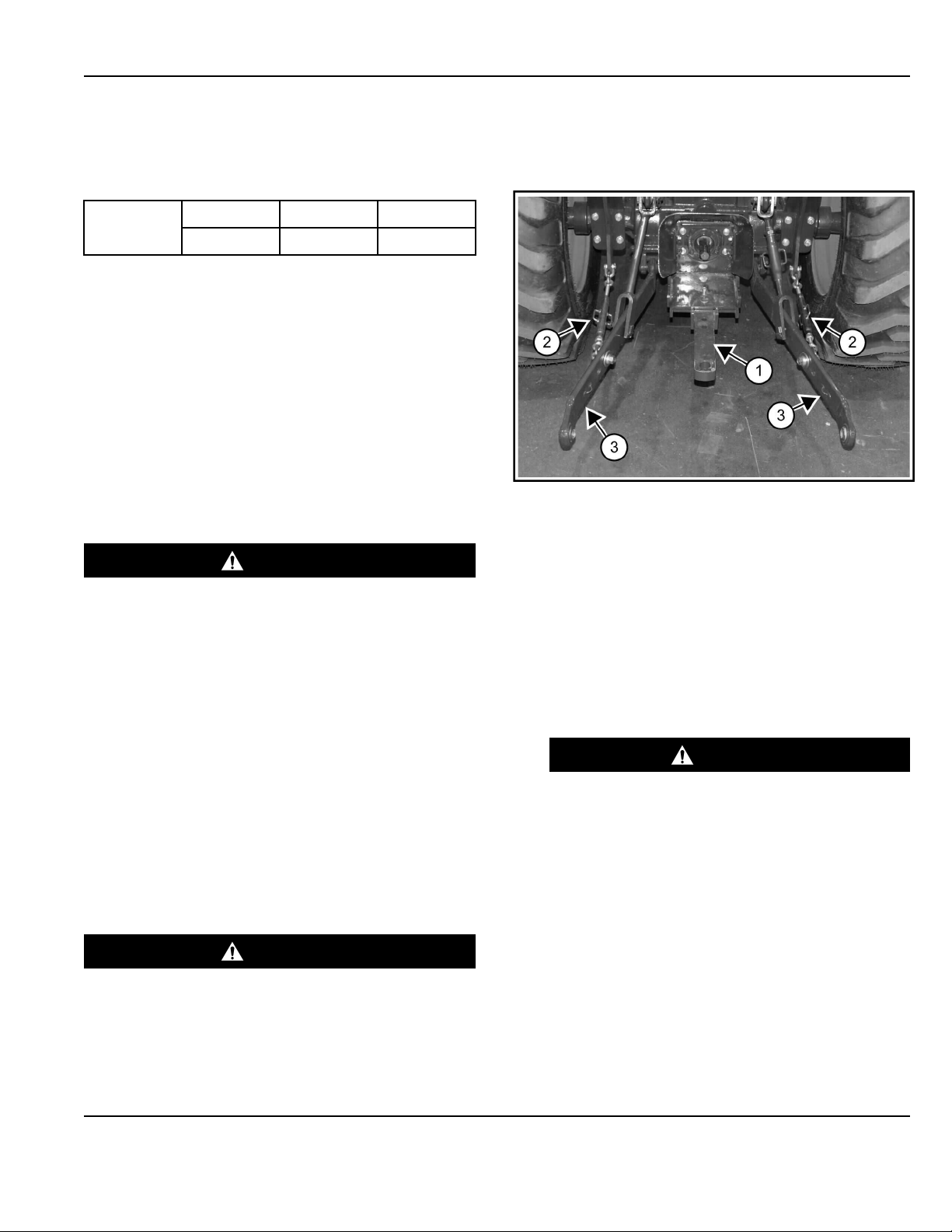
Figure 8
c138256a
1. Move the drawbar (Item 1) [Figure 8] to the storage
position or remove (if necessary). See the compact
tractor Operation & Maintenance Manual for detailed
information.
The three-point hitch lower links must be set wide
enough to clear the implement mounting pins.
2. Adjust the sway bars (Item 2) (both sides) to move
the lower links (Item 3) [Figure 8] as needed.
See the compact tractor Operation & Maintenance
Manual for detailed information on adjusting sway
bars.
WARNING
CRUSHING HAZARD
Contact with the machine can cause serious
injury or death.
Before backing the machine, look in all
directions and make sure no bystanders are in
the work area. Do not allow anyone between the
machine and the implement when backing up to
the implement for installation. ◂
W-2734
3. Enter the compact tractor
(See Entering And Exiting The Compact Tractor on
Page 11) .
4. Start the engine and release the parking brake.
OPERATING INSTRUCTIONS

12
Figure 9
P142006a
5. Drive the compact tractor to the implement and align
the lower links (Item 1) with the implement lower
mounts (Item 2) [Figure 9] (both sides).
6. Lower or raise the compact tractor three-point hitch
lower links (Item 1) until they are even with the lower
mounts (Item 2) [Figure 9] (both sides) of the three-
point implement.
See the compact tractor Operation & Maintenance
Manual for detailed information on operating the
compact tractor.
7. Stop the engine and exit the compact tractor.
(See Entering And Exiting The Compact Tractor on
Page 11)
WARNING
PINCHING HAZARD
Failure to follow instructions can cause serious
injury.
Keep fingers and hands out of pinch points when
installing and removing implement or
attachments.◂
W-2571
Figure 10
P142005a
8. Install the lower implement pin (Item 1) through the
lower mounts and lower link (Item 2) [Figure 10]
(both sides) and secure with retaining clip.
Figure 11
c138244a
9. Remove the top link (Item 1) from the storage
position bracket (Item 2) [Figure 11].
OPERATING INSTRUCTIONS
13
Figure 12
c138245a
10. Lower the top link (Item 3) [Figure 12] until it aligns
with the implement upper mounting hole.
11. Install the pin (Item 2) and retainer pin (Item 1)
[Figure 12].
NOTE: It may be necessary to lengthen or shorten
the top link to align it with the implement
mounting hold [Figure 12].
12. The implement can be leveled front to back by
adjusting the top link.
13. The implement side to side sway will need to be
adjusted. (See Adjusting The Sway Bar on Page 14)
Raising The Storage Stand
NOTE: Your machine and attachment and / or implement
models may vary, but the procedure is the same.
1. Enter the compact tractor.
(See Entering And Exiting The Compact Tractor on
Page 11)
2. Start the engine and release the parking brake.
3. Always park on flat level ground. Raise the three-
point implement slightly above the ground. See the
tractor Operation & Maintenance Manual for detailed
information on operating the three-point hitch.
4. Stop the engine and exit the compact tractor.
(See Entering And Exiting The Compact Tractor on
Page 11)
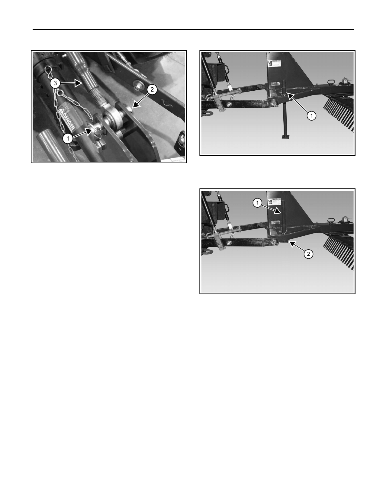
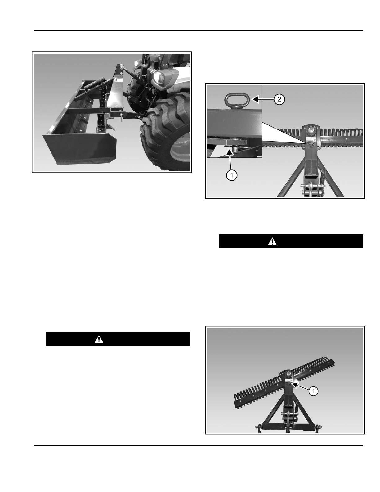
Figure 13
P-96309a
5. Remove the retaining pin (Item 1) [Figure 13]
Figure 14
P-96331a
6. Raise the storage stand (Item 1) [Figure 14].
7. Align the holes and install the retaining pin (Item 2)
[Figure 14].
OPERATING INSTRUCTIONS

14
Adjusting The Lift Link
Figure 15
p138247b
The lift link (Item 1) [Figure 15] is used to adjust the side
to side level of the implement.
See the compact tractor Operation & Maintenance
Manual for detailed information on adjusting the lift link.
Adjusting The Sway Bar
Figure 16
c138248a
The sway bar (Item 1) [Figure 16] (both sides) are used to
center the implement between the tires and limits the
implements side to side movement.
Adjust the sway bars to center the implement between
the tires. See the compact tractor Operation &
Maintenance Manual for detailed information on adjusting
sway bars.
When adjusting the sway bars with implement installed,
the implement will need to be raised slightly off the
ground.
Control Functions Three-Point Hitch
(Implement)
The three-point hitch will be used to raise or lower the
implement. (See the compact tractor Operation &
Maintenance Manual for detailed information on
operating the three-point hitch).
Driving The Implement And Tractor To
Worksite
The following images may not show your exact three-
point implement but the procedure is the same.
WARNING
GENERAL HAZARD
Steering and braking can be affected by the loader
attachment, implements, front wheel assist and the
rear differential lock.
Always install the correct ballast. Do not exceed the
Loader or Three-Point Hitch lift capacities.
Always carry loads low. Slow down when turning.
Always lock the brake pedals together (if equipped)
for road travel.
Unlock the brake pedals (if equipped) only when
using brake pedals to assist in slow speed turns in
work applications.
Make sure that the brakes are adjusted correctly so
the compact tractor does not pull to one side when
braking.◂
W-2738
WARNING
INSTABILITY HAZARD
Failure to obey warnings can cause the machine to
rollover.
• Use ROPS and fasten the seat belt.
• Install the correct rear ballast.
• Do NOT exceed the Loader lift capacity.
• Check tire condition and proper air pressure.
• Use tires with the correct load rating.◂
W-3043
1. Enter the compact tractor.
(See Entering And Exiting The Compact Tractor on
Page 11)
2. Start the engine.
OPERATING INSTRUCTIONS
15
Figure 17
P142007g
3. Raise the implement to the travel position
[Figure 17]. See the compact tractor Operation &
Maintenance Manual for detailed information on
operating the three-point hitch.
4. Drive the compact tractor and implement to the work
area.
5. When operating on public road or highway, always
follow local regulations. For example; Slow Moving
Vehicle (SMV) emblem or directional signals and
hazard / flasher lights may be required.
6. Park on flat level ground.
7. Lower the implement slightly above the ground. (See
the compact tractor Operation & Maintenance
Manual for detailed information on operating the
three-point hitch.)
8. Stop the engine and exit the compact tractor.
(See Entering And Exiting The Compact Tractor on
Page 11)
WARNING
UNINTENDED MOVEMENT HAZARD
Failure to follow instructions can cause serious
injury or death.
Before you leave the operator’s seat:
Fully lower the loader arms, put the attachment
flat on the ground (if equipped).
Fully lower the implement(s) to the ground (if
equipped).
Lock brake pedals together (if equipped) and
engage the parking brake.
Place all controls in neutral.
Stop the engine, unfasten the seat belt, and
remove the key.◂
W-3178
Angled Positioning
NOTE: Your machine and attachment and / or implement
models may vary, but the procedure is the same.
Figure 18
C217656a
1. Remove the lower retaining pin (Item 1) [Figure 18].
2. Remove the locking pin (Item 2) [Figure 18].
WARNING
PINCHING HAZARD
Failure to follow instructions can cause serious
injury.
Keep fingers and hands out of pinch points when
installing and removing implement or
attachments.◂
W-2571
3. Rotate the implement to one of the forward angled
positions.
Figure 19
P-96315a
OPERATING INSTRUCTIONS

16
4. Install the locking pin (Item 1) [Figure 19] and lower
retaining pin.
Backfilling Positioning
The following images may not show your exact three-
point implement but the procedure is the same.
Figure 20
C217656a
1. Remove the lower retaining pin (Item 1) [Figure 20].
2. Remove the locking pin (Item 2) [Figure 20].
WARNING
PINCHING HAZARD
Failure to follow instructions can cause serious
injury.
Keep fingers and hands out of pinch points when
installing and removing implement or
attachments.◂
W-2571
3. Rotate the implement 180° or to a rearward angled
position. Install the locking pin (Item 1) [Figure 20]
and retaining.
Operating The Three-Point Implement
The three-point tine rake can be used for leveling and
landscaping.
1. Park on flat level ground. Lower the three-point tine
rake slightly above the ground. See the compact
tractor Operation & Maintenance Manual for detailed
information on operating the three-point hitch.
2. Stop the engine and exit the compact tractor.
(See Entering And Exiting The Compact Tractor on
Page 11)
WARNING
UNINTENDED MOVEMENT HAZARD
Failure to follow instructions can cause serious
injury or death.
Before you leave the operator’s seat:
Fully lower the loader arms, put the attachment
flat on the ground (if equipped).
Fully lower the implement(s) to the ground (if
equipped).
Lock brake pedals together (if equipped) and
engage the parking brake.
Place all controls in neutral.
Stop the engine, unfasten the seat belt, and
remove the key.◂
W-3178
3. Adjust the three-point tine rake in any single or
combination of the following position:
a. Angled (See Angled Positioning on Page 15)
b. Backfilling
(See Backfilling Positioning on Page 16)
4. Enter the compact tractor
(See Entering And Exiting The Compact Tractor on
Page 11) . Start the engine and release the parking
brake.
WARNING
GENERAL HAZARD
Failure to follow instructions can cause serious
injury or death.
• Fasten seat belt, start, and operate only from
the operator’s seat.
• Never wear loose clothing when working near
machine.◂
W-2135
5. Slowly drive the tractor with the three-point tine rake
on the ground. Adjust the three-point hitch for
desired position. See the compact tractor Operation
& Maintenance Manual for detailed information
operating the three-point hitch.
6. The top link may need to be adjusted to set the rake
times to the correct positions.
Watch for and avoid obstructions and obstacles that
could cause damage to the three-point tine rake and
compact tractor.
Damage to the three-point tine rake and compact
tractor may occur by hitting hidden objects.
Removing The Three-Point Implement
Lowering The Storage Stand
NOTE: Your machine and attachment and / or implement
models may vary, but the procedure is the same.
OPERATING INSTRUCTIONS

17
In muddy conditions or to prevent the implement from
freezing to the ground, put the implement on planks or
blocks before removing the implement from the machine.
WARNING
UNINTENDED MOVEMENT HAZARD
Failure to follow instructions can cause serious
injury or death.
Before you leave the operator’s seat:
Fully lower the loader arms, put the attachment flat
on the ground (if equipped).
Fully lower the implement(s) to the ground (if
equipped).
Lock brake pedals together (if equipped) and engage
the parking brake.
Place all controls in neutral.
Stop the engine, unfasten the seat belt, and remove
the key.◂
W-3178
1. Always park on flat, level ground. Fully lower the
loader arms and put the attachment flat on the
ground (if equipped).
2. Lower the three-point implement slightly above the
ground. See the compact tractor Operation &
Maintenance Manual for detailed information on
operating the three-point hitch.
3. Stop the engine and exit the compact tractor.
(See Entering And Exiting The Compact Tractor on
Page 11)
WARNING
CRUSHING HAZARD
Failure to follow instructions can cause serious
injury or death.
Do not stand between the machine and
attachment / implement.
Keep bystanders away.
Install support stands before disconnecting
attachment / implement from the machine.◂
W-2724
Figure 21
P-96331b
4. Remove the retaining pin (Item 1) [Figure 21].
Figure 22
P-96309b
5. Lower the storage stand (Item 1) [Figure 22]. Align
the holes and install the retaining pin (Item 2)
[Figure 22].
6. Enter the compact tractor.
(See Entering And Exiting The Compact Tractor on
Page 11)
7. Start the engine and release the parking brake.
8. Lower the three-point setting the implement on the
ground. See the compact tractor Operation &
Maintenance Manual for detailed information on
operating the three-point hitch.
9. Stop the engine and exit the compact tractor.
(See Entering And Exiting The Compact Tractor on
Page 11)
OPERATING INSTRUCTIONS

18
Removing The Three-Point Implement
Figure 23
C138245a
1. Remove the retainer pin (Item 1) and pin (Item 2)
[Figure 23].
It may be necessary to lengthen or shorten the top
link when remove the implement from the compact
tractor.
2. Remove the top link (Item 3) [Figure 23] from the
implement.
Figure 24
138244a
3. Place the top link (Item 1) into the storage position
bracket (Item 2) [Figure 24].
Figure 25
P142005a
4. Remove the lower implement pin (Item 1) from the
lower mounts and lower link (Item 2) [Figure 25].
5. Enter the compact tractor.
(See Entering And Exiting The Compact Tractor on
Page 11)
6. Start the engine and release the parking brake.
Figure 26
P142006c
7. Slowly drive the compact tractor away from the
implement [Figure 26].
8. Remove the front ballast from the compact tractor (if
equipped).
OPERATING INSTRUCTIONS
This manual suits for next models
2
Table of contents
Other Ignite Tractor Accessories manuals


