Ignite Blade Box 48 Manual

7495908enUS (A)
October 2022
Printed in USA
Original Instructions
© 2022 Ignite Attachments.
All Rights Reserved.
Operation & Maintenance Manual
Three-Point Box Blade
Blade Box 48 S/N: B63Y00101 & Above
Blade Box 60 S/N: B63Z00101 & Above
Blade Box 72 S/N: B64100101 & Above


1
FOREWORD............................................................................................................................................................3
MANUFACTURER.............................................................................................................................................3
North America ...............................................................................................................................................3
SERIAL NUMBER LOCATION ...........................................................................................................................3
Implement Serial Number ................................................................................................................................3
IMPLEMENT IDENTIFICATION ..........................................................................................................................4
Rear O Implement..........................................................................................................................................4
Front Of Implement ........................................................................................................................................4
STANDARD ITEMS ...........................................................................................................................................5
SAFETY AND TRAINING RESOURCES....................................................................................................................6
SAFETY INSTRUCTIONS..................................................................................................................................6
Safe Operation Is The Operator’s Responsibility (Implement) ..................................................................................6
Use Safety Rules ...........................................................................................................................................6
Call Before You Dig ........................................................................................................................................6
Silica Dust Exposure.......................................................................................................................................6
FIRE PREVENTION...........................................................................................................................................7
Maintenance.................................................................................................................................................7
Operation.....................................................................................................................................................7
Electrical......................................................................................................................................................7
Hydraulic System...........................................................................................................................................7
Fueling ........................................................................................................................................................8
Starting........................................................................................................................................................8
Spark Arrester Exhaust System......................................................................................................................... 8
Welding And Grinding .....................................................................................................................................8
Fire Extinguishers ..........................................................................................................................................8
PUBLICATIONS AND TRAINING RESOURCES .................................................................................................9
IMPLEMENT SIGNS (DECALS) .........................................................................................................................9
OPERATING INSTRUCTIONS ................................................................................................................................ 10
DAILY INSPECTION........................................................................................................................................ 10
Implement Mounting Frame............................................................................................................................ 10
Three-Point Hitch......................................................................................................................................... 10
OPERATING PROCEDURE WITH COMPACT TRACTORS ............................................................................... 11
Approved Compact Tractor Models And Requirements ........................................................................................ 11
Setting Up The Ballast................................................................................................................................... 11
Entering And Exiting The Compact Tractor ........................................................................................................ 11
Installing The Three-Point Implement ............................................................................................................... 11
Control Functions Three-Point Hitch (Implement) ................................................................................................ 14
Driving The Implement And Tractor To Worksite.................................................................................................. 14
Operating The Scraper Blade ......................................................................................................................... 15
Operating The Backfill Blade .......................................................................................................................... 15
Adjusting The Scarifier Teeth .......................................................................................................................... 16
Removing The Three-Point Implement.............................................................................................................. 16
LIFTING THE IMPLEMENT.............................................................................................................................. 17
TRANSPORTING THE IMPLEMENT ON A TRAILER ........................................................................................ 18
Fastening The Implement On A Trailer.............................................................................................................. 18
TRANSPORTING THE IMPLEMENT AND MACHINE ON A TRAILER................................................................ 18
Transporting The Attachment And Machine On A Trailer ....................................................................................... 18
PREVENTIVE MAINTENANCE............................................................................................................................... 20
TABLE OF CONTENTS

2
MAINTENANCE SAFETY WARNINGS ............................................................................................................. 20
TROUBLESHOOTING ..................................................................................................................................... 21
Troubleshooting The Implement ...................................................................................................................... 21
SERVICE SCHEDULE ..................................................................................................................................... 22
Maintenance Intervals................................................................................................................................... 22
CUTTING EDGE.............................................................................................................................................. 22
Removing And Installing The Cutting Edge ........................................................................................................ 22
SCARIFIER TEETH ......................................................................................................................................... 23
Removing And Installing Scarifier Teeth ............................................................................................................ 23
STORAGE AND RETURN TO SERVICE........................................................................................................... 24
Implement Storage....................................................................................................................................... 24
Return To Service ........................................................................................................................................ 24
SPECIFICATIONS.................................................................................................................................................. 25
IMPLEMENT DIMENSIONS ............................................................................................................................. 25
PERFORMANCE SPECIFICATIONS ................................................................................................................ 26
WARRANTY .......................................................................................................................................................... 27
IMPLEMENT WARRANTY ............................................................................................................................... 27
TABLE OF CONTENTS

3
MANUFACTURER
North America
Ignite Attachments
2741 20th Avenue South
Moorhead, MN 56560
SERIAL NUMBER LOCATION
Implement Serial Number
Figure 1
P142002f
Always use the serial number of the three-point box blade
when requesting service information or when ordering
parts. Earlier or later models (identification made by serial
number) may use different parts, or it may be necessary
to use a different procedure in doing a specific service
operation [Figure 1].
FOREWORD


6
SAFETY INSTRUCTIONS
Safe Operation Is The Operator’s
Responsibility (Implement)
Safety Alert Symbol
This symbol with a warning statement means:
“Warning, be alert! Your safety is involved!” Carefully
read the message that follows.
DANGER
The signal word DANGER on machine signs and in
the manuals indicates a hazardous situation which, if
not avoided, will result in serious injury or death.◂
D-1002
WARNING
The signal word WARNING on the machine and in the
manuals indicates a potentially hazardous situation
which, if not avoided, could result in serious injury or
death.◂
W-2044
IMPORTANT
This notice identifies procedures which must be
followed to avoid damage to the machine.◂
I-2019
The machine and implement must be in good operating
condition before use.
Check all of the items on the Service Schedule decal (if
equipped) in the Every 10 Hours section or as shown in
the Operation & Maintenance Manual.
Use Safety Rules
• Read and follow instructions in the machine and the
implement’s Operation & Maintenance Manual
before operating.
• Check for underground lines before operating
implement (if applicable).
• In addition to the design and configuration of
equipment, hazard control, and accident prevention
are dependent upon the awareness, concern,
prudence, and proper training of personnel involved
in the operation, transport, maintenance, and
storage of equipment.
• Check that the implement is securely fastened to the
machine.
• Make sure all the machine controls are in the neutral
position before starting the machine.
• Operate the implement only from the operator’s
position.
• Operate the implement according to the Operation &
Maintenance Manual.
• When learning to operate the implement, do it at a
slow rate in an area clear of bystanders.
• DO NOT permit personnel to be in the work area
when operating the machine and implement.
• The implement must be used ONLY on approved
machines. Visit [Missing external cross reference
text] for an updated list of approved implements for
each machine model.
• DO NOT modify equipment or add implements that
are not approved by the manufacturer.
• DO NOT make any adjustments or repairs on the
machine or implement while the engine is running.
• Keep shields and guards in place. Replace if
damaged.
Call Before You Dig
P200081
Dial 811 (USA Only)
Dial 1-888-258-0808 (USA & Canada)
When you call, you will be directed to a location in your
state / province / city for information about buried lines
(telephone, cable TV, water, sewer, gas, etc.).
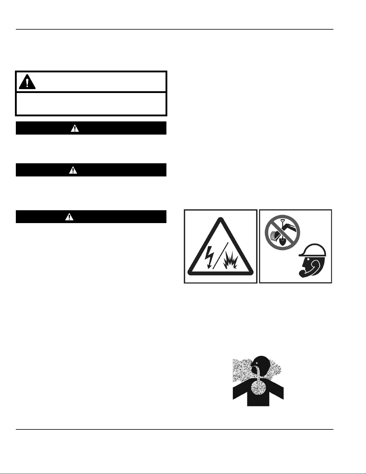
Silica Dust Exposure
NA3504
SAFETY AND TRAINING RESOURCES

7
Silica dust can cause lung disease and is known to the
state of California to cause cancer.
Cutting or drilling concrete containing sand or rock
containing quartz may result in exposure to silica dust.
Do not exceed Permissible Exposure Limits (PEL) to
silica dust as determined by OSHA or other job site Rules
and Regulations. Use a respirator, water spray, or other
means to control dust.
FIRE PREVENTION
NA3505
Maintenance
The machine and some attachments have components
that are at high temperatures under normal operating
conditions. The primary source of high temperatures is
the engine and exhaust system. The electrical system, if
damaged or incorrectly maintained, can be a source of
arcs or sparks.
Flammable debris (leaves, straw, etc.) must be removed
regularly. If flammable debris is allowed to accumulate, it
can cause a fire hazard. Clean often to avoid this
accumulation. Flammable debris in the engine
compartment is a potential fire hazard.
The operator’s area, engine compartment, and engine
cooling system must be inspected every day and cleaned
if necessary to prevent fire hazards and overheating.
All fuels, most lubricants, and some coolants mixtures are
flammable. Flammable fluids that are leaking or spilled
onto hot surfaces or onto electrical components can
cause a fire.
Operation
Do not use the machine where exhaust, arcs, sparks, or
hot components can contact flammable material,
explosive dust, or gases.
Electrical
P200082
Check all electrical wiring and connections for damage.
Keep the battery terminals clean and tight. Repair or
replace any damaged part or wires that are loose or
frayed.
Battery gas can explode and cause serious injury. Use
the procedure in the Operation & Maintenance Manual for
connecting the battery and for jump starting. Do not jump
start or charge a frozen or damaged battery. Keep any
open flames or sparks away from batteries. Do not
smoke in battery charging area.
Hydraulic System
Check hydraulic tubes, hoses and fittings for damage and
leakage. Never use open flame or bare skin to check for
SAFETY AND TRAINING RESOURCES

8
leaks. Hydraulic tubes and hoses must be properly routed
and have adequate support and secure clamps. Tighten
or replace any parts that show leakage.
Always clean fluid spills. Do not use gasoline or diesel
fuel for cleaning parts. Use commercial nonflammable
solvents.
Fueling
P200084
Stop the engine and let it cool before adding fuel. No
smoking! Do not refuel a machine near open flames or
sparks. Fill the fuel tank outdoors.
Ultra Low Sulfur Diesel (ULSD) poses a greater static
ignition hazard than earlier diesel formulations with
higher sulfur content. Avoid death or serious injury from
fire or explosion. Consult with your fuel or fuel system
supplier to ensure the delivery system is in compliance
with fueling standards for proper grounding and bonding
practices.
Starting
Do not use ether or starting fluids on any engine that has
glow plugs or an air intake heater. These starting aids
can cause explosion and injure you or bystanders.
Use the procedure in the Operation & Maintenance
Manual for connecting the battery and for jump starting.
Spark Arrester Exhaust System
The spark arrester exhaust system is designed to control
the emission of hot particles from the engine and exhaust
system, but the muffler and the exhaust gases are still
hot.
Check the spark arrester exhaust system regularly to
make sure it is maintained and working properly. Use the
procedure in the Operation & Maintenance Manual for
cleaning the spark arrester muffler (if equipped).
Welding And Grinding
Always clean the machine and implement, disconnect the
battery, and disconnect the wiring from the Ignite
Attachments controllers before welding. Cover rubber
hoses, battery, and all other flammable parts. Keep a fire
extinguisher near the machine when welding.
Have good ventilation when grinding or welding painted
parts. Wear a dust mask when grinding painted parts.
Toxic dust or gas can be produced.
Dust generated from repairing nonmetallic parts such as
hoods, fenders, or covers can be flammable or explosive.
Repair such components in a well-ventilated area away
from open flames or sparks.
Fire Extinguishers
P200083
Know where fire extinguishers and first aid kits are
located and how to use them. Inspect the fire
extinguisher and service the fire extinguisher regularly.
Obey the recommendations on the instructions plate.
SAFETY AND TRAINING RESOURCES

9
PUBLICATIONS AND TRAINING
RESOURCES
The following publications are also available for your
Ignite Attachments machine. Access them online at
Igniteattachments.com.
P217312
Operation & Maintenance
Manual
Complete instructions on
the correct operation and
the routine maintenance
of your attachment.
7495908
For the latest information on Ignite Attachments products
and the Ignite Attachments Company, visit our website at
Igniteattachments.com
IMPLEMENT SIGNS (DECALS)
Figure 4
P142002d
REF. DECAL
1 Crush Warning
Located near 3 point hitch, both sides
71892000IG
SAFETY AND TRAINING RESOURCES

10
DAILY INSPECTION
Implement Mounting Frame
Figure 5
P142002e
Inspect the lower implement mounts (Item 1) and upper
mount (Item 2) [Figure 5] and all welds for wear and
damage each time the implement is removed from the
machine.
Check the following items at the start of a work day:
• Check for damaged or missing decals. Replace if
necessary.
• Replace any worn or damaged parts immediately.
Three-Point Hitch
WARNING
UNINTENDED MOVEMENT HAZARD
Failure to follow instructions can cause serious
injury or death.
The parking brake must be engaged before leaving
the operator’s seat. Rollaway can occur because the
transmission may not prevent machine movement.
Lock the brake pedals together (if equipped) before
activating the parking brake.◂
W-2656
Figure 6
c138256
• Inspect the three-point hitch linkage, PTO shaft
splines, guards, and shields. Replace if damaged or
missing [Figure 6].
Repair broken or loose parts.
See your machine Operation & Maintenance Manual
for detailed information on inspecting three-point
hitch.
OPERATING INSTRUCTIONS
11
OPERATING PROCEDURE WITH COMPACT
TRACTORS
Approved Compact Tractor Models And
Requirements
Box Blade
48
Box Blade
60
Box Blade
72
Tractor HP 18–30 26–65 35–65
The chart shows the approved box blade models for
compact tractors based on horsepower.
Warranty on this implement is void if used on a non-
approved carrier. Contact your Ignite Attachments
representative for a current list of compatible carriers.
Setting Up The Ballast
Install the correct ballast on the compact tractor before
installing the three-point box blade. See the compact
tractor Operation & Maintenance Manual for ballast
information.
Entering And Exiting The Compact Tractor
WARNING
INSTABILITY HAZARD
Failure to obey warnings can cause the machine to
rollover.
• Use Roll-Over Protective Structure (ROPS) and
fasten the seat belt.
• Install the correct rear ballast.
• Do NOT exceed the Loader lift capacity.
• Check tire condition and proper air pressure.
• Use tires with the correct load rating.◂
W-3043
See your compact tractor Operation & Maintenance
Manual for detailed instructions on entering and exiting
the machine.
Installing The Three-Point Implement
Always inspect the compact tractor three-point hitch and
implement three-point mounting before installation.
(See Daily Inspection on Page 10) .
WARNING
GENERAL HAZARD
Failure to obey warnings can cause serious injury or
death.
Obey all warnings on the machine and in the
manuals.◂
W-2744
Figure 7
c138256a
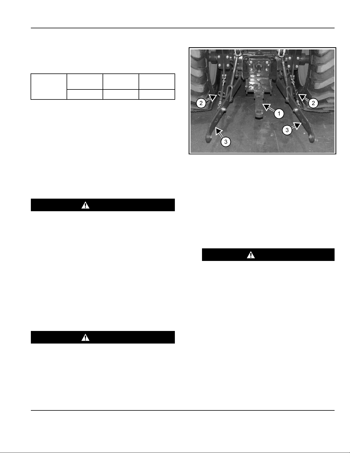
1. Move the drawbar (Item 1) [Figure 7] to the storage
position or remove (if necessary). See the compact
tractor Operation & Maintenance Manual for detailed
information.
The three-point hitch lower links must be set wide
enough to clear the implement mounting pins.
2. Adjust the sway bars (Item 2) (both sides) to move
the lower links (Item 3) [Figure 7] as needed.
See the compact tractor Operation & Maintenance
Manual for detailed information on adjusting sway
bars.
WARNING
CRUSHING HAZARD
Contact with the machine can cause serious
injury or death.
Before backing the machine, look in all
directions and make sure no bystanders are in
the work area. Do not allow anyone between the
machine and the implement when backing up to
the implement for installation. ◂
W-2734
3. Enter the compact tractor
(See Entering And Exiting The Compact Tractor on
Page 11) .
4. Start the engine and release the parking brake.
OPERATING INSTRUCTIONS

12
Figure 8
P142006a
5. Drive the compact tractor to the implement and align
the lower links (Item 1) with the implement lower
mounts (Item 2) [Figure 8] (both sides).
6. Lower or raise the compact tractor three-point hitch
lower links (Item 1) until they are even with the lower
mounts (Item 2) [Figure 8] (both sides) of the three-
point implement.
See the compact tractor Operation & Maintenance
Manual for detailed information on operating the
compact tractor.
7. Stop the engine and exit the compact tractor.
(See Entering And Exiting The Compact Tractor on
Page 11)
WARNING
PINCHING HAZARD
Failure to follow instructions can cause serious
injury.
Keep fingers and hands out of pinch points when
installing and removing implement or
attachments.◂
W-2571
Figure 9
P142005a
8. Install the lower implement pin (Item 1) through the
lower mounts and lower link (Item 2) [Figure 9] (both
sides) and secure with retaining clip.
Figure 10
c138244a
9. Remove the top link (Item 1) from the storage
position bracket (Item 2) [Figure 10].
OPERATING INSTRUCTIONS

13
Figure 11
c138245a
10. Lower the top link (Item 1) [Figure 11] until it aligns
with the implement upper mounting hole.
11. Install the pin (Item 2) and retainer pin (Item 3)
[Figure 11].
NOTE: It may be necessary to lengthen or shorten
the top link to align it with the implement
mounting hold [Figure 11].
(See Adjusting The Top Link on Page 13)
12. The implement can be leveled front to back by
adjusting the top link.
(See Adjusting The Top Link on Page 13)
13. The implement side to side sway will need to be
adjusted. (See Adjusting The Sway Bar on Page 14)
Adjusting The Lift Link
Figure 12
p138247b
The lift link (Item 1) [Figure 12] is used to adjust the side
to side level of the implement.
See the compact tractor Operation & Maintenance
Manual for detailed information on adjusting the lift link.
Adjusting The Top Link
Figure 13
c138246a
The top link (Item 1) [Figure 13] is used to adjust the front
to back level of the implement.
1. Loosen the locknut (Item 2) and use the adjuster
(Item 3) [Figure 13] to lengthen or shorten the top
link.
2. Turn clockwise to lengthen the top link, turn
counterclockwise to shorten top link.
3. After the implement has been leveled, tighten the
locknut (Item 2) [Figure 13].
OPERATING INSTRUCTIONS

14
Adjusting The Sway Bar
Figure 14
c138248a
The sway bar (Item 1) [Figure 14] (both sides) are used to
center the implement between the tires and limits the
implements side to side movement.
Adjust the sway bars to center the implement between
the tires. See the compact tractor Operation &
Maintenance Manual for detailed information on adjusting
sway bars.
When adjusting the sway bars with implement installed,
the implement will need to be raised slightly off the
ground.
Control Functions Three-Point Hitch
(Implement)
The three-point hitch will be used to raise or lower the
implement. (See the compact tractor Operation &
Maintenance Manual for detailed information on
operating the three-point hitch).
Driving The Implement And Tractor To
Worksite
WARNING
GENERAL HAZARD
Steering and braking can be affected by the loader
attachment, implements, front wheel assist and the
rear differential lock.
Always install the correct ballast. Do not exceed the
Loader or Three-Point Hitch lift capacities.
Always carry loads low. Slow down when turning.
Always lock the brake pedals together (if equipped)
for road travel.
Unlock the brake pedals (if equipped) only when
using brake pedals to assist in slow speed turns in
work applications.
Make sure that the brakes are adjusted correctly so
the compact tractor does not pull to one side when
braking.◂
W-2738
WARNING
INSTABILITY HAZARD
Failure to obey warnings can cause the machine to
rollover.
• Use ROPS and fasten the seat belt.
• Install the correct rear ballast.
• Do NOT exceed the Loader lift capacity.
• Check tire condition and proper air pressure.
• Use tires with the correct load rating.◂
W-3043
1. Enter the compact tractor.
(See Entering And Exiting The Compact Tractor on
Page 11) .
2. Start the engine.
Figure 15
P142007g
OPERATING INSTRUCTIONS

15
3. Raise the three-point box blade to the travel position
[Figure 15]. See the compact tractor Operation &
Maintenance Manual for detailed information on
operating the three-point hitch.)
4. Drive the compact tractor and implement to the work
area.
5. When operating on public road or highway, always
follow local regulations. For example; Slow Moving
Vehicle (SMV) emblem or directional signals and
hazard / flasher lights may be required.
6. Park on flat level ground.
7. Lower the three-point box blade slightly above the
ground. (See the compact tractor Operation &
Maintenance Manual for detailed information on
operating the three-point hitch.)
8. Stop the engine and exit the compact tractor.
(See Entering And Exiting The Compact Tractor on
Page 11)
WARNING
UNINTENDED MOVEMENT HAZARD
Failure to follow instructions can cause serious
injury or death.
Before you leave the operator’s seat:
Fully lower the loader arms, put the attachment
flat on the ground (if equipped).
Fully lower the implement(s) to the ground (if
equipped).
Lock brake pedals together (if equipped) and
engage the parking brake.
Place all controls in neutral.
Stop the engine, unfasten the seat belt, and
remove the key.◂
W-3178
Operating The Scraper Blade
1. When at the area to be scraped, stop the tractor,
lower the box blade from the travel position to the
ground.
2. Exit the compact tractor.
(See Entering And Exiting The Compact Tractor on
Page 11)
3. Adjust the top link to set the cutting edge at the
correct angle.
(See Adjusting The Top Link on Page 13)
4. Enter the compact tractor.
(See Entering And Exiting The Compact Tractor on
Page 11)
5. Slowly drive the tractor forward scraping the box
blade across the ground with the three-point lift
control in the float position.
6. Watch for and avoid obstructions and obstacles that
may cause damage to the box blade and compact
tractor.
7. When done with the pass, lift the box blade, turn the
tractor around, lower the box blade to the ground,
and continue until the area is finished.
Operating The Backfill Blade
The top link is critical in all backfilling operations. Adjust
the top link so the blade is tilted down at the rear, causing
the blade to move across the ground and not digging into
the ground. (See Adjusting The Top Link on Page 13)
• Use a slow speed and caution to prevent damage to
the box blade while using the backfill blade.
• The backfilling operation should be performed with
the load in the center of the blade. Avoids loads at
the ends of the blades.
• Do not ram into a load, this may cause damage to
the box blade and compact tractor.
• Perform all backfilling operations at slow speeds to
prevent damage if the blade hits an object.
• Moving snow with the backfilling blade is a delicate
operation and should be done at a slower speed and
with caution.
NOTE: Damage to the box blade and compact
tractor may occur by hitting hidden objects.
• Damage to the box blade may occur by hitting
objects that can be hidden easily in the snow, or a
snow bank that is too much material to move.
• Use caution when using the box blade for snow
removal because the compact tractor may suddenly
lose and regain traction causing a sudden surge of
ground speed.
OPERATING INSTRUCTIONS

16
Adjusting The Scarifier Teeth
Figure 16
P142022b
1. Remove the retaining pin (Item 1), locking pin (Item
2), and adjust the scarifier (Item 3) [Figure 16] to the
desired position.
2. Insert locking pin and retaining pin.
Removing The Three-Point Implement
Figure 17
C138245a
1. Remove the retainer pin (Item 1) and pin (Item 2)
[Figure 17].
It may be necessary to lengthen or shorten the top
link when remove the implement from the compact
tractor. (See Adjusting The Top Link on Page 13)
2. Remove the top link (Item 3) [Figure 17] from the
implement.
Figure 18
138244a
3. Place the top link (Item 1) into the storage position
bracket (Item 2) [Figure 18].
Figure 19
P142005a
4. Remove the lower implement pin (Item 1) from the
lower mounts and lower link (Item 2) [Figure 19]
5. Enter the compact tractor.
(See Entering And Exiting The Compact Tractor on
Page 11)
6. Start the engine and release the parking brake.
OPERATING INSTRUCTIONS

17
Figure 20
P142006c
7. Slowly drive the compact tractor away from the
implement [Figure 20]
8. Remove the front ballast from the compact tractor (if
equipped).
LIFTING THE IMPLEMENT
Use chains that are in good condition and of adequate
size to lift the implement.
Figure 21
C141660a
• Fasten the chains to the three-point box blade (Item
1) [Figure 21].
OPERATING INSTRUCTIONS

18
TRANSPORTING THE IMPLEMENT ON A
TRAILER
Fastening The Implement On A Trailer
Figure 22
C141661a
Figure 23
C141662a
• Fasten the chains to the implement (Item 1)
[Figure 22] and [Figure 23] and fasten each end of
the chain to the transport vehicle.
• Use chain binders to prevent the implement from
moving during transport.
TRANSPORTING THE IMPLEMENT AND
MACHINE ON A TRAILER
Transporting The Attachment And Machine
On A Trailer
WARNING
INSTABILITY HAZARD
Wood ramps can break and cause personal injury.
Use adequately designed ramps of sufficient
strength to support the weight of the machine
loading onto a transport vehicle.◂
W-2058
Be sure the transport and towing vehicles are of
adequate size and capacity for weight of machine and
attachment combination. (See machine and attachment
Operation & Maintenance Manuals for specifications)
Loading
• The rear of the trailer must be blocked or supported
when loading and unloading to prevent the front of
the trailer from raising.
• Load the heaviest end of the machine and
attachment combination first.
• Lower the attachment to the floor.
• Turn the machine off.
• Engage the parking brake (if equipped).
• Exit the machine. (See the machine’s Operation
& Maintenance Manual for the correct
procedure.)
Fastening
• Install the chains at the front and rear tie-down
positions on the machine. (See the machine’s
Operation & Maintenance Manual to properly chain
the machine to the transport vehicle.)
• Install chains on the attachment (if required).
• Fasten each end of the chain to the transport
vehicle.
NOTE: Use chain binders to prevent the attachment
and machine from moving during transport.
OPERATING INSTRUCTIONS
This manual suits for next models
2
Table of contents
Other Ignite Tractor Accessories manuals

Popular Tractor Accessories manuals by other brands


Cover My Tractor
Cover My Tractor Bimini Assembly instructions

Tiger
Tiger BENGAL 5085M Series Mounting and operating instructions

Swisher
Swisher 20020 owner's manual

HE-VA
HE-VA Top-Cutter Solo operating instructions

Original Tractor Cabs
Original Tractor Cabs CAB 12152 Assembly instructions

HOLMS
HOLMS KHV 280 SMS bracket Operator instructions


