Koyker 145 User manual

OWNERS MANUAL
MANUAL NO. 669516
LOADER
IMPORTANT - KOYKER DEALER
BE SURE THIS MANUAL IS GIVEN TO THE
PURCHASER FOR FUTURE REFERENCE
KOYKER MFG. CO., P.O. BOX 409
LENNOX, SD 57039
Phone: 1-800-456-1107 E-mail: koyker@koykermfg.com
9/05/07

CONTENTS
CONTENTS PAGE
Introduction.................................................................................................................................................. 1
SAFETY INFORMATION
Safety Alert Symbol..................................................................................................................................... 2
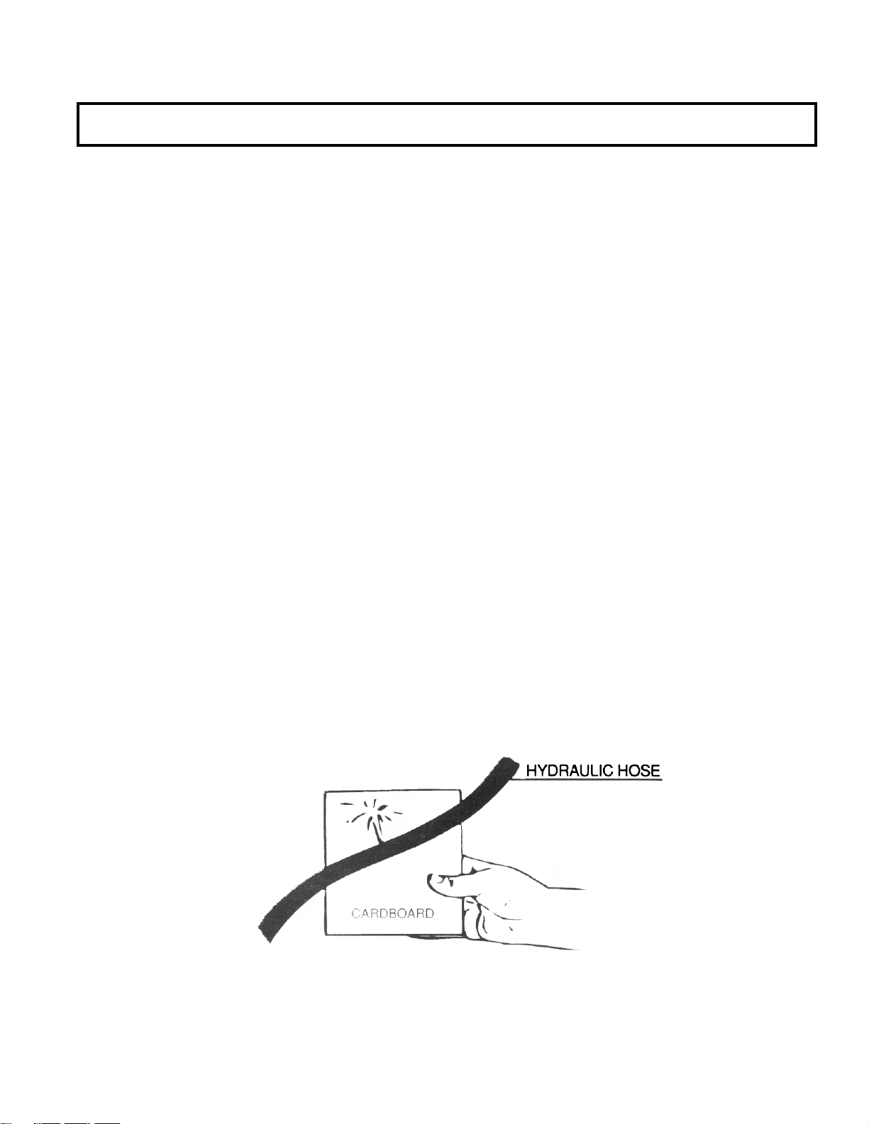
Safety Information .....................................................................................................................................3-5
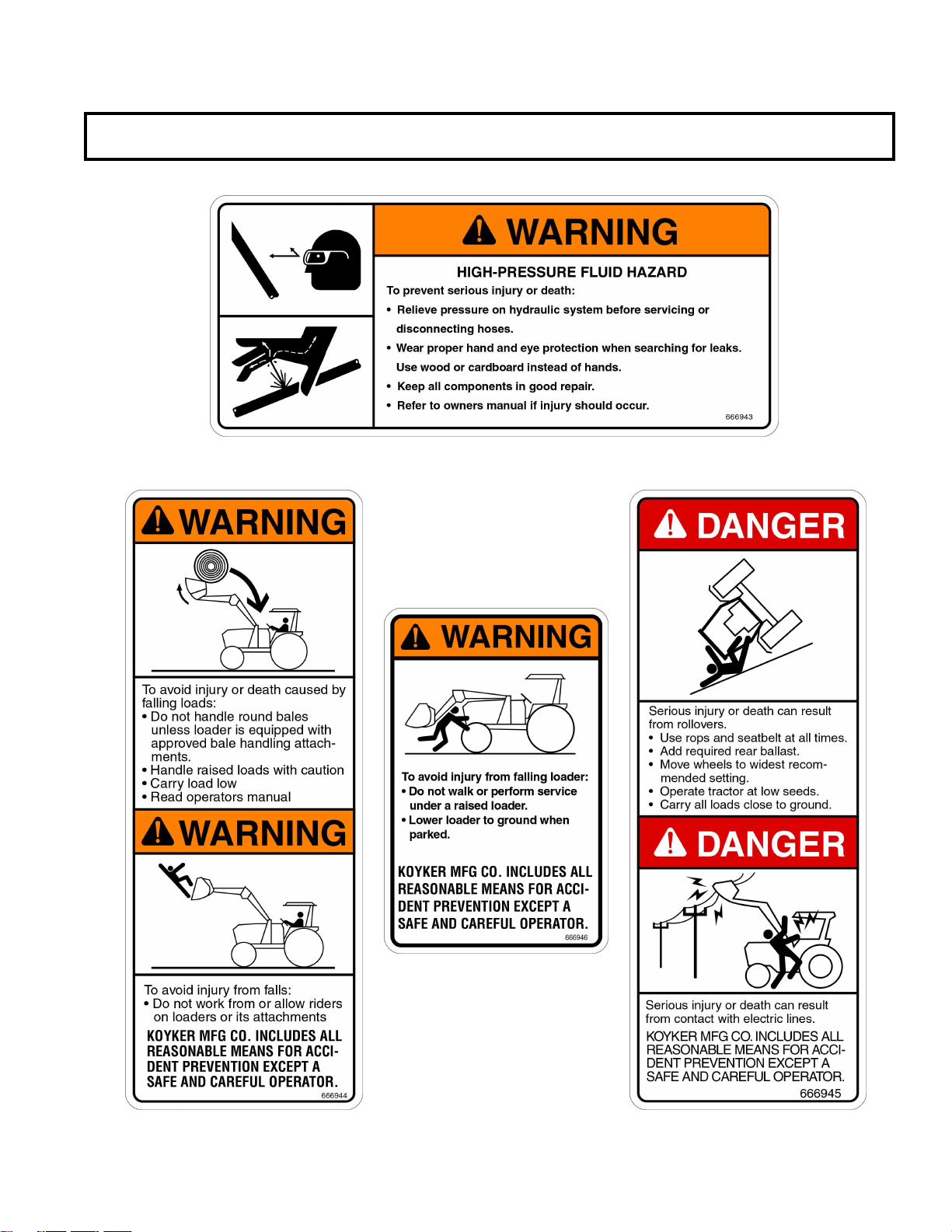
Safety Decals ............................................................................................................................................... 6
Tractor & Safety Pointers .............................................................................................................................7
ASSEMBLY INSTRUCTIONS
Attaching Loader ......................................................................................................................................... 8
Attaching Bucket ......................................................................................................................................... 9
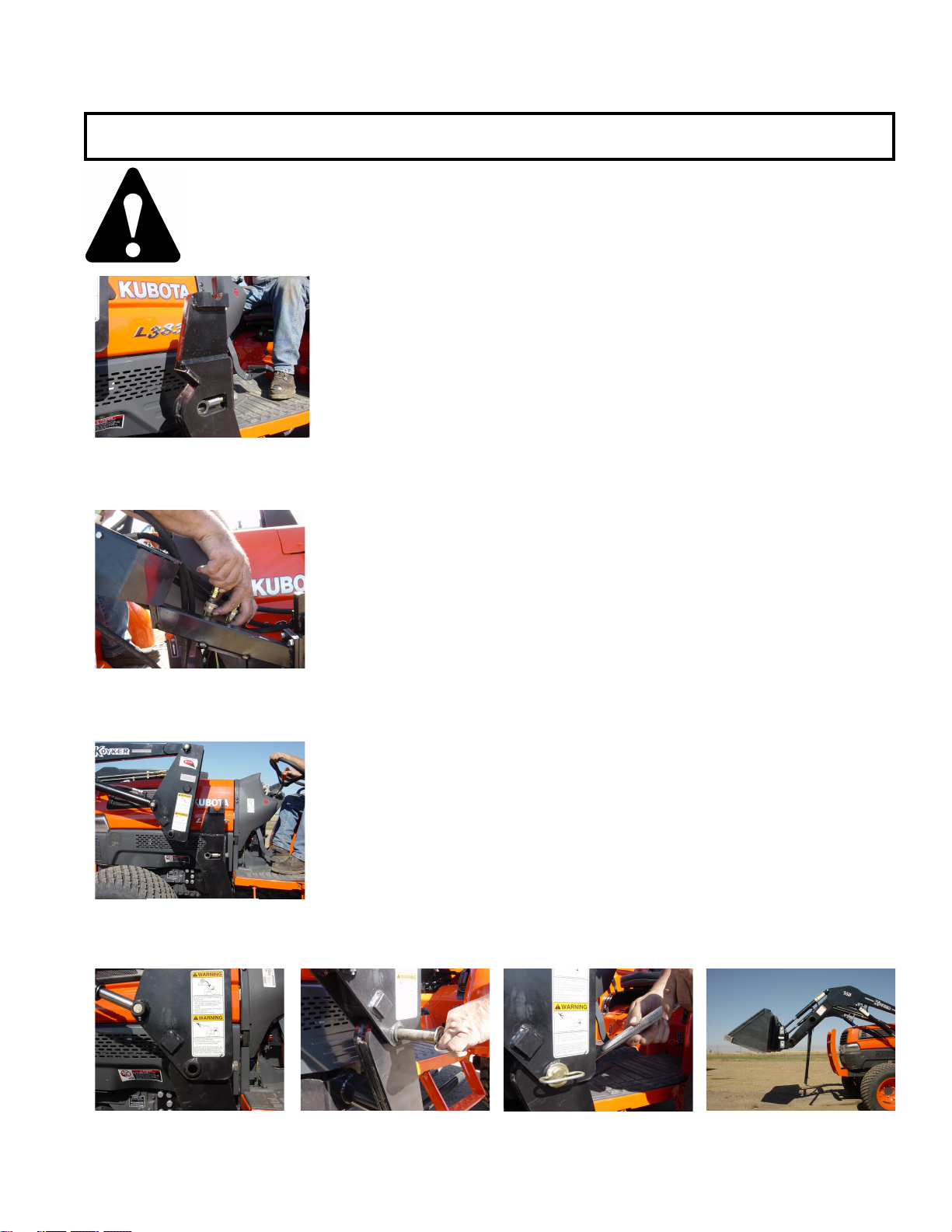
Detaching Loader........................................................................................................................................ 10
OPERATING INSTRUCTIONS
Operation…………………………………………………………………………………………………..11
SERVICE AND MAINTENANCE
Specifications…………………………………………………………………………………………….12-13
Loader Inspection, Lubrication, and Maintenance ..................................................................................... 14
Hydraulic System Parts List........................................................................................................................ 15
Hydraulic System Parts Diagram................................................................................................................ 16
“145” Loader Parts Diagram....................................................................................................................... 17
Parts Identification Schedule ....................................................................................................................18-19
“145” Skid Steer Adapter Diagram............................................................................................................. 20
Parts Identification Schedule ...................................................................................................................... 21
Hydraulic Cylinders Information................................................................................................................ 22
1 3/4” Cylinder Service Kit......................................................................................................................... 23
2” Cylinder Service Kit............................................................................................................................... 24
Cylinder Parts List ...................................................................................................................................... 25
Cylinder Parts Diagram............................................................................................................................... 26
Piston and Gland Diagram ......................................................................................................................... 27
Dinoil Valve Hookup.................................................................................................................................. 28
LIMITED WARRANTY INFORMATION
Limited Warranty......................................................................................................................................29-31
TORQUE SPECIFICATIONS
Torque Specifications ................................................................................................................................. 32

INTRODUCTION
For years, Koyker Manufacturing Company of Lennox, South Dakota, has provided the loader industry
with innovative ideas for a more efficient and dependable means of material handling. Now, with the
increasing popularity of the MFWD (Mechanical Front Wheel Drive) tractors, Koyker has again met the
challenge and provided the market with a loader that will allow the efficient use of these tractors in
material handling. The KOYKER 145 Loader provides you with state-of-the-art design and innovation for
your material handling chores.
Features such as quality construction, ease of maintenance, and high performance operating capacities, all
at a low price, make the new 145 Loader one of the most efficient loaders ever. With proper care and
handling, it will provide many years of dependable service.
This manual is designed to provide you with important information regarding the basic loader and bucket.
Our sincere intent, in providing this manual, is to help you or those involved better understand the machine
and to prevent accidents.
Should you have any questions, comments, improvements, or suggestions regarding the contents of any of
the manuals provided, please contact Koyker Manufacturing Company (800-456-1107 or E-mail
We care about your safety!
Remember ALL safety decals are no charge from the factory. Please replace all safety decals if
missing or damaged. Your safety is important to us.
Page 1

SAFETYALERT SYMBOL
The symbol shown below is used to call your attention to instructions concerning your personal safety.
Watch for this symbol, it points out important safety precautions. It means ATTENTION! Become
Alert! Your Personal Safety Is Involved!
Read the message that follows and be alert to the possibility of personal injury or death.
DANGER: Indicates an imminently hazardous situation that, if not avoided, will result in death or serious
injury.
WARNING: Indicates a potentially hazardous situation that, if not avoided, could result in death or
serious injury.
CAUTION: Indicates a potentially hazardous situation that, if not avoided may result in minor or
moderate injury.
WARNING!
Anyone who will operate or work around a front-end loader should first read this
manual.
Page 2

SAFETY
Improper use of a loader can cause serious injury or death. The following safety precautions, and those
given on the tractor mount installation instructions, should be thoroughly understood before attempting to
operate this machine.
BEFORE OPERATING:
Carefully study and understand this manual, the specific tractor mount instructions, and the
attachment(s) manual(s).
Prior to operation, inspect the loader for system leaks and damaged, missing, or malfunctioning
components in an effort to avoid the possibility of a dangerous failure involving structural
members or hydraulic system components.
Be certain any repairs necessary are completed prior to loader operation.
Follow recommended maintenance procedures and precautions on Page 13.
Completely familiarize yourself and others involved with the operation of the hydraulic control
valve before operating the loader.
Be certain all bystanders are clear of the machine and operation area prior to operation.
It may be necessary to add wheel ballast or rear weights as recommended by the tractor
manufacturer to maintain stability of the machine to prevent tipping or upset which could result in
serious injury or death. See mounting instructions for specific information.
It is recommended that both front and rear wheel treads be set to the widest recommended width to
prevent tipping or upset which could result in serious injury or death.
This loader is designed for farm type operations such as snow removal, barn and feedlot cleaning,
light commercial or light grading and digging. It’s design is NOT intended for commercial and/or
industrial use.
DURING OPERATION:
Never operate the machine other than from the tractor operator’s seat.
Be sure operating area is clear of others during machine operations.
Never lift, hoist, or carry humans in the bucket or on any portion of the loader or loader
attachments. Failure to heed, may result in serious injury or death.
Page 3

SAFETY CONTINUED
Transport the machine load at the slowest speed possible and with the loader boom at the lowest
transport position to avoid tipping or upsetting, which may result in serious injury or death.
Be extremely careful when working on inclines or near loose fill, rocks, and holes as they can cause
tipping or upsetting which may result in serious injury or death.
Be certain to avoid overhead electrical wires when operating loader. Contact with power lines may
cause serious injury or death.
Avoid sudden stops when lowering or lifting the loader boom to prevent loss of control over the
machine and/or load, which may result in serious injury or death.
Use maximum ballast and the widest recommended wheel setting on your tractor when handling
large shiftable loads.
Never attempt to ram with the bucket at high speed or full tractor power. Sudden impact may result
in structural failure and possible serious injury or death.
Never adjust or perform maintenance on the loader or tractor with the unit in motion, or without
power source locked out.
Never get under bucket or lift arms or reach through the lift arms or bucket linkage when the loader
is in operation. Inadvertent movement may cause serious injury or death.
FOLLOWING OPERATION:
Whenever the machine is not in operation, lower the loader boom and set the tractor brakes,
disengage drive, shut the engine off, and remove the ignition key before dismounting the tractor.
If loader is to be disengaged from tractor, be sure the loader is securely supported on a hard, level
surface and the stand is securely engaged. Be certain all connections between tractor and loader are
free before disengaging.
TRANSPORTING:
Use safety lights and SMV emblem in addition to whatever local codes require when equipment is
being transported on the road or highway. Check with proper authorities for legal limitations.
Transport all loads at a slow and safe speed.
Carry the load as low as possible and maintain adequate visibility and good round clearance at all
times.
Page 4

SAFETY CONTINUED
PERFORMING MAINTENANCE:
Carefully review, understand, and follow the “maintenance” section in this owners manual before
attempting to service loader.
Lower the bucket or attachment to the ground, shut off tractor engine, and relieve pressure in the
hydraulic system before adjusting, lubricating, or servicing the loader.
Escaping hydraulic oil under pressure can penetrate the skin. Never use any part of your body to
check for hydraulic leaks. Use cardboard when checking for leaks. See Fig. 5-1. Relieve
hydraulic pressure before disconnecting any hydraulic line. Failure to heed may result in serious
injury or death.
Before disconnecting hydraulic lines, lower the loader and attachments. Lock out the hydraulic
supply and relieve all hydraulic pressure.
Replace any damaged or painted-over decals. See Page 6 for replacement decals.
REMEMBER:
1. Move Slowly!
2. Always use care and common sense!
3. Be careful for your own sake and for that of others!
4. Koyker Mfg. Co. includes all reasonable means for accident prevention except a safe and
careful operator.
FIG. 5-1
Page 5

SAFETY DECALS
Page 6

The use of good judgment and common sense is necessary by the operator in using this loader. The front
and rear wheels should be set for the widest wheel tread to assure best stability. Use extra caution when
rear wheel weights and tire ballast are added to a loader-equipped tractor. DO NOT ram into frozen dirt
piles, frozen manure piles, ice, etc., with great momentum where sudden shock loads are encountered.
Serious and costly damage may result to both the loader and the tractor.
When scraping or back dragging do not extend the attachment cylinders more than one half of the
cylinder’s stroke. A limited amount of leveling may be done, when the loader valving is arranged with a
float control. This will prevent damage to cylinder rods. Never ride in the bucket.
Before operating the loader, be sure no one is standing near it. Only one person, the operator, should be on
the tractor. Remain at the controls and under no circumstances leave the tractor unattended with the bucket
in a raised position.
Never lift a person in the bucket or walk under a raised bucket.
Never drive your loader-equipped tractor down a hill that is steeper than 15 degrees. Carry all loads low
and use care on side hills.
Always keep unused PTO shaft clutch levers disengaged.
Keep hands, feet, and clothing away from all moving parts.
Hydraulic oil, under pressure, can cause injury. Be sure that all connections are tight and that all pressure
is relieved before disconnecting any lines.
Care must be taken with your loader cylinders. Nicks, scratches, rust, or other shaft damage can result in
worn packing causing cylinder leakage and subnormal performance.
MOVE SLOWLY
USE COMMON SENSE
BE CAREFUL FOR YOUR OWN SAKE AND THAT OF OTHER PEOPLE
TRACTOR & SAFETY POINTERS
Page 7

ATTACHING LOADER
IMPORTANT:
Never attempt loader attachment on grades which are not reasonably level.
1. Check to be sure that the surfaces of the mounts are free of
obstructions. (Fig 8-1)
2. Drive the tractor slowly and carefully in between the loader arms
only far enough to permit hook-up of the hydraulic system hoses.
(Fig. 8-2)
3. Once all hoses have been properly coupled drive the tractor forward
checking to insure that the top pivot shaft on each loader upright
clears the top cradle on each mount tower. (Fig. 8-3)
4. Allow the top pivot shaft to settle into the cradle on the top of each
mount tower. After the uprights slide into the mount raise the loader
slowly to engage firmly into the mount cradles. (Fig. 8-4)
5. To lock the loader onto the mount, install the two 665421 – 1”
diameter mount pins into the outside of the upright through the mount
tightener, and pin with hitch pin on other side. (Fig. 8-5)
6. To secure the loader to the mount tighten the 3/4” bolt at the back of
the mount tower. (Fig. 8-6) Re-check bolts after first three hours of
use.
7. After both uprights are secured to the mounts, raise the loader still
further to disengage and store the loader stands in the torque tube of
the loader frame. (Fig 8-7)
8. Prior to operation, be certain to review all safety and operation
information contained within this manual. Check bolts on back of
mount or the first 3 hours of use, then check periodically during
normal maintenance procedure.
Page 8
Fig 8-1
Fig 8-7Fig 8-4 Fig 8-6Fig 8-5
Fig 8-3
Fig 8-2

ATTACHING THE BUCKET
Page 9
1. For pin on buckets, assemble pins and retaining bolts as shown in the Parts Diagram of this manual.
Make sure all retaining bolts are secure and lubricate necessary points. Inspect pin and bolts
periodically for tightness and wear.
2. For Fast Attach Buckets, tilt the bucket adapter forward so the top wedge of the adapter slides
under the round pipe on the bucket. Rotate the bucket back so the two pin holes line up between
the bucket and adapter. Push both pins through bucket and adapter, and secure with clips. Inspect
pins periodically for wear.

DETACHING LOADER
Page 10
IMPORTANT:
Never attempt loader attachment on grades which are not reasonably level.
1. Raise loader frame slightly to permit loader stand reengagement.
(Fig. 10-1)
2. Lower bucket to ground and tip slightly forward to apply
pressure to mount connection. Note: This will prevent
the loader from inadvertently rocking forward when the mount
pins are removed and uprights are disengaged from it’s cradle.
(Fig. 10-2)
3. Loosen the 3/4” bolt at the back of the mount enough to permit
the removal of the mount pins. (Fig. 10-3)
4. Use the lift cylinders to disengage the bottom anchor bar from the
mount tower. Then tilt the bucket back to rotate the top of the
upright up and out of the cradle, and into a storage position.
(Fig. 10-4)
5. Before completely backing out, disconnect and store the loader
system hydraulic hoses. It is important that the hoses be properly
stored to keep the hose couplers as clean as possible. (Fig. 10-5)
IMPORTANT:
Never store the detached loader where insufficient soil
bearing capacity exists. Good firm clay or firmly packed dirt are
sufficient, providing the area is dry. If you are unsure, use blocking
under the stand foot to disperse the load. Failure to heed, may allow
the loader to settle and prevent attachment at later date.
WARNING:
Re-couple any hydraulic hoses together for your particular system when necessary to prevent
damage to tractor hydraulics. See your particular mount of hydraulic hook-up instructions.
Fig 10-1
Fig 10-2
Fig 10-3 Fig 10-5
Fig 10-4

WARNING:
Never allow anyone to operate the loader until they have carefully reviewed and
understood this owners manual.
FILLING THE BUCKET:
Approach and enter the pile with the bucket level.
Roll bucket back gradually as the loader moves through the pile.
RAISING THE BUCKET:
WARNING:
Make sure material in bucket cannot spill out on to tractor when loader boom is
raised. Keep clear of overhead obstructions such as trees, limbs or power lines when
raising the bucket.
Side cutting is the best method of reducing large stockpiles. If the sides of the pile
are too high, use the loader to pull them down and reduce the possibility of slides.
WARNING:
NEVER attempt to operate the loader with someone near the loader frame or bucket.
OPERATION
Page 11

Page 3Page 12
SPECIFICATIONS
KOYKER 145 LOADER SPECIFICATIONS
Description of Equipment Rated
Loader Model..................................................................................................................... 145
Bucket Size ..........................................................................................................................4’
Rated Flow.......................................................................................................................6 GPM
Maximum Pressure (using Koyker valve) .....................................................................2200 PSI
Lift Cylinder Dia..........................................................................................................1 3/4” Bore
Attachment Cylinder Dia.............................................................................................1 3/4” Bore
Tractor Horsepower Range............................................................................................20-45 HP
Dimensional Specifications
(A) *Maximum Lift Height to Pivot Pin........................................................................... 8’ 5”
(B) *Lift Height under Level Bucket............................................................................... 7’ 10”
(C) *Clearance with Bucket Fully Dumped...................................................................... 6’ 7”
(D) *Reach at Maximum Lift Height............................................................................... 1’ 10”
(E) Maximum Dump Angle................................................................................................50°
(F) *Reach with Bucket on Ground.................................................................................. 4’ 1”
(G) Maximum Rollback Angle...........................................................................................23°
(H) *Digging Depth.............................................................................................................5”
(J) *Overall Height in Carry Position............................................................................... 4’ 9”
Operational Specifications
(U) *Lift Capacity to Maximum Height at Pivot Pin ....................................................1320 lbs.
(V) *Lift Capacity to Maximum Height 19.7” Forward of Pivot Pin.............................990 lbs.
(Y) *Breakout Force at Ground Line at Pivot Pin.........................................................2370 lbs.
(Z) *Breakout Force at Ground Line 19.7” Forward of Pivot Pin.................................1800 lbs.
*Raising Time................................................................................................................3 seconds
*Lower Time..................................................................................................................2 seconds
*Attachment Dumping Time .........................................................................................3 seconds
*Attachment Rollback Time..........................................................................................2 seconds
*Specifications based on ASABE standards S301.3 (Front-End Agricultural Loader Ratings) The above
information is based on testing done by Koyker Mfg. Variations in maximum lift height and other specs for
different tractors are due to tire sizes, variations in loader mounting locations and hydraulic system
efficiency.
Specifications are subject to change without notice and without liability therefore.

Page 3Page 13
SPECIFICATIONS
KOYKER 145 LOADER SPECIFICATIONS
Description of Equipment Rated
Loader Model..................................................................................................................... 145
Bucket Size ..........................................................................................................................4’
Rated Flow.......................................................................................................................6 GPM
Maximum Pressure (using Koyker valve) .....................................................................2200 PSI
Lift Cylinder Dia.............................................................................................................2” Bore
Attachment Cylinder Dia................................................................................................ 2” Bore
Tractor Horsepower Range............................................................................................20-45 HP
Dimensional Specifications
(A) *Maximum Lift Height to Pivot Pin........................................................................... 8’ 5”
(B) *Lift Height under Level Bucket............................................................................... 7’ 10”
(C) *Clearance with Bucket Fully Dumped...................................................................... 6’ 7”
(D) *Reach at Maximum Lift Height............................................................................... 1’ 10”
(E) Maximum Dump Angle................................................................................................50°
(F) *Reach with Bucket on Ground.................................................................................. 4’ 1”
(G) Maximum Rollback Angle...........................................................................................23°
(H) *Digging Depth.............................................................................................................5”
(J) *Overall Height in Carry Position............................................................................... 4’ 9”
Operational Specifications
(U) *Lift Capacity to Maximum Height at Pivot Pin ....................................................1810 lbs.
(V) *Lift Capacity to Maximum Height 19.7” Forward of Pivot Pin............................1350 lbs.
(Y) *Breakout Force at Ground Line at Pivot Pin.........................................................3210 lbs.
(Z) *Breakout Force at Ground Line 19.7” Forward of Pivot Pin.................................2440 lbs.
*Raising Time................................................................................................................4 seconds
*Lower Time..................................................................................................................3 seconds
*Attachment Dumping Time .........................................................................................3 seconds
*Attachment Rollback Time..........................................................................................2 seconds
*Specifications based on ASABE standards S301.3 (Front-End Agricultural Loader Ratings) The above
information is based on testing done by Koyker Mfg. Variations in maximum lift height and other specs for
different tractors are due to tire sizes, variations in loader mounting locations and hydraulic system
efficiency.
Specifications are subject to change without notice and without liability therefore.

LOADER INSPECTION, LUBRICATION, AND MAINTENANCE
Lower the bucket to the ground, shut off tractor engine, and relieve the pressure in the hydraulic system
before adjusting, lubricating, or servicing the loader.
Inspect all pins and grease fittings before each use and lubricate with heavy duty grease as indicated in this
manual.
Periodically check all bolts for looseness and re-torque if necessary.
Before storage, be certain all hydraulic cylinders are fully collapsed so that the rod will not be exposed to
the elements or damaged.
Be certain hydraulic system remains sealed at all times to prevent contamination.
Check and maintain an adequate fluid level in the tractor reservoir prior to use.
Inspect all hydraulic system hoses and fittings. Replace prior to further operation if damaged.
WARNING:
Escaping hydraulic oil under pressure can penetrate the skin. Never use any part of your
body to check for hydraulic leaks. Use cardboard when checking for leaks. See Fig. 14-1.
Relieve hydraulic pressure before disconnecting any hydraulic line. Failure to heed may
result in serious injury or death.
FIG. 14-1
Page 14

KEY PART NUMBER DESCRIPTION QUANTITY
1...................... 655615................. 1st Oil Line (Green)...........................................................1
2...................... 655616................. 2nd Oil Line (Yellow)........................................................1
3...................... 655617................. 3rd Oil Line (Blue).............................................................1
4 ..................... 655618................. 4th Oil Line (Red)..............................................................1
5...................... 672304................. 2” Lift Cylinder..................................................................2
6...................... 672400................. 2” Bucket Cylinder ............................................................2
7...................... 672288................. 14” Hydraulic Hose............................................................2
8 ..................... 672289................. 21” Hydraulic Hose............................................................2
9...................... 672287................. 14” Hydraulic Hose............................................................4
OPTIONAL CYLINDERS
10..................... 672305................. 1 3/4” Lift Cylinder............................................................2
11..................... 672403................. 1 3/4” Bucket Cylinder ......................................................2
HYDRAULIC SYSTEM PARTS LIST
Page 15

HYDRAULIC SYSTEM PARTS DIAGRAM
Page 16

KOYKER “145” LOADER PARTS DIAGRAM
Page 17

KEY PART NUMBER DESCRIPTION QUANTITY
1...................... 672300................. Main Frame........................................................................1
2...................... 672301................. RH Upright.........................................................................1
3...................... 672302................. LH Upright ........................................................................1
4...................... 672304................. 2” Lift Cylinder .................................................................2
5...................... 672400................. 2” Bucket Cylinder ............................................................2
6...................... 677641................. “145” Decal........................................................................2
7...................... 666941................. Serial Number Decal..........................................................1
8...................... 660807................. 4 5/8” Pivot Pin..................................................................4
9...................... 660808................. 5 1/4” Pivot Pin..................................................................4
10..................... 660809................. Oil Line Cover ...................................................................1
11..................... 673281................. Stand . ................................................................................2
12..................... 665421................. Mount Pin...........................................................................2
13..................... 661997................. Oil Line Clamp .................................................................14
14..................... 661998................. Oil Line Spacer..................................................................3
15..................... 672288................. 14” Hydraulic Hose............................................................2
16..................... 672289................. 21” Hydraulic Hose............................................................2
17..................... 640246................. #6 Hitch Pin .......................................................................2
18..................... 641119................. Lock Pin.............................................................................2
19..................... 640671................. #3 Hitch Pin .......................................................................4
20..................... 654629................. “American Made” Decal....................................................2
21L ................... 677676................. “KOYKER” Decal Left .....................................................1
21R................... 677677................. “KOYKER” Decal Right...................................................1
22..................... 655615................. 1st Oil Line .......................................................................1
23..................... 655616................. 2nd Oil Line.......................................................................1
24..................... 655617................. 3rd Oil Line........................................................................1
25..................... 655618................. 4th Oil Line........................................................................1
26..................... 640128................. Locknut; 5/16” ..................................................................6
27..................... 651703................. HH Cap Screw; 1/4” x 2”..................................................8
28..................... 640126................. Locknut; 1/4” ....................................................................8
29..................... 672287................. 14” Hydraulic Hose............................................................4
30..................... 666943................. Warning Decal ...................................................................5
31..................... 666944................. Warning Decal ...................................................................1
32..................... 666945................. Danger Decal .....................................................................1
33..................... 666946................. Warning Decal ...................................................................2
34..................... 675840................. Indicator Rod .....................................................................1
35..................... 675841................. Indicator Sleeve .................................................................1
36..................... 640128................. Locknut; 5/16” ..................................................................1
37..................... 652360................. Hexnut; 5/16”....................................................................1
38..................... 651880................. HH Cap Screw; 5/16” x 1 1/4” .........................................1
PARTS IDENTIFICATION SCHEDULE
Page 18
Table of contents
Other Koyker Tractor Accessories manuals
Popular Tractor Accessories manuals by other brands

Avantco
Avantco A441007 Operator's manual for Attachment

Avantco
Avantco A36841 Operator's manual for Attachment

Avantco
Avantco A36262 Operator's manual for Attachment

Avantco
Avantco A35411 Operator's manual for Attachment

Spraying Systems
Spraying Systems TeeJet Matrix 908 user guide

matev
matev SRM-FB 130 Original operating manual